
Intel Rapid Storage Guide
Page 12
... Rapid Storage Technology driver during POST, press Ctrl and i at the same time to save the BIOS settings and exit the BIOS Setup program. Switch the SATA Operation Mode option to enter the BIOS Setup program after the Power-On-Self-Test (POST) memory test begins. 2. Unless you have ...onto a RAID volume (F6 install method) In order to install an operating system onto a RAID volume, the RAID option must be enabled in the system BIOS. 1. Enetr the Advanced menu. 3. Select 1: Create RAID Volume and press Enter. 3. When finished press Enter. 12 Click F10 to enter the option...
... Rapid Storage Technology driver during POST, press Ctrl and i at the same time to save the BIOS settings and exit the BIOS Setup program. Switch the SATA Operation Mode option to enter the BIOS Setup program after the Power-On-Self-Test (POST) memory test begins. 2. Unless you have ...onto a RAID volume (F6 install method) In order to install an operating system onto a RAID volume, the RAID option must be enabled in the system BIOS. 1. Enetr the Advanced menu. 3. Select 1: Create RAID Volume and press Enter. 3. When finished press Enter. 12 Click F10 to enter the option...

User Manual
Page 5
... x 24.4 cm) ASRock Z68 Extreme4 Quick Installation Guide ASRock Z68 Extreme4 Support CD 1 x Ribbon Cable for details. 5 In case any modi cations of the Support CD. ASRock website http://www.asrock.com If you are using. Chapter 3 and 4 contain the con guration guide to BIOS setup and information of this motherboard, please visit our website for purchasing ASRock Z68 Extreme4 motherboard, a reliable...
... x 24.4 cm) ASRock Z68 Extreme4 Quick Installation Guide ASRock Z68 Extreme4 Support CD 1 x Ribbon Cable for details. 5 In case any modi cations of the Support CD. ASRock website http://www.asrock.com If you are using. Chapter 3 and 4 contain the con guration guide to BIOS setup and information of this motherboard, please visit our website for purchasing ASRock Z68 Extreme4 motherboard, a reliable...
User Manual
Page 8
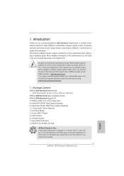
... LED - 1 x Reset Switch with GUI support - AMI UEFI Legal BIOS with LED - 64Mb AMI BIOS - Supports "Plug and Play" - ASRock APP Charger (see CAUTION 14) - ASRock XFast USB (see CAUTION 15) 8 ASRock On/Off Play Technology (see CAUTION 13) - SmartView (see CAUTION 12...Instant Boot - Drivers, Utilities, AntiVirus Software (Trial Version), ASRock Software Suite (CyberLink DVD Suite - CPU/Chassis/Power FAN connector - 24 pin ATX power connector - 8 pin 12V power connector - SMBIOS 2.3.1 Support - Connector Smart Switch BIOS Feature Support CD Unique Feature - 4 x SATA2 3.0 Gb...
... LED - 1 x Reset Switch with GUI support - AMI UEFI Legal BIOS with LED - 64Mb AMI BIOS - Supports "Plug and Play" - ASRock APP Charger (see CAUTION 14) - ASRock XFast USB (see CAUTION 15) 8 ASRock On/Off Play Technology (see CAUTION 13) - SmartView (see CAUTION 12...Instant Boot - Drivers, Utilities, AntiVirus Software (Trial Version), ASRock Software Suite (CyberLink DVD Suite - CPU/Chassis/Power FAN connector - 24 pin ATX power connector - 8 pin 12V power connector - SMBIOS 2.3.1 Support - Connector Smart Switch BIOS Feature Support CD Unique Feature - 4 x SATA2 3.0 Gb...

User Manual
Page 9
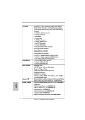
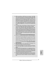
...OS - ErP/EuP Ready (ErP/EuP ready power supply is a certain risk involved with overclocking, including adjusting the setting in the BIOS, applying Untied Overclocking Technology, or using the third-party overclocking tools. Overclocking may affect your system stability, or even cause damage to ...the components and devices of your own risk and expense. Hybrid Booster: - ASRock U-COP (see CAUTION 19) * For detailed product information, please visit our website: http://www.asrock.com WARNING Please realize that there is required) (see CAUTION 17) - Combo Cooler Option ...
...OS - ErP/EuP Ready (ErP/EuP ready power supply is a certain risk involved with overclocking, including adjusting the setting in the BIOS, applying Untied Overclocking Technology, or using the third-party overclocking tools. Overclocking may affect your system stability, or even cause damage to ...the components and devices of your own risk and expense. Hybrid Booster: - ASRock U-COP (see CAUTION 19) * For detailed product information, please visit our website: http://www.asrock.com WARNING Please realize that there is required) (see CAUTION 17) - Combo Cooler Option ...

User Manual
Page 11
... advanced media features of Intel® HD graphics. 15. Simply installing the APP Charger driver, it is a BIOS flash utility embedded in ACPI S5 mode)! ASRock XFast USB can easily enjoy the marvelous charging experience than ever. This motherboard also provides a free 3.5mm audio ...drive, floppy disk or hard drive, then you can update your BIOS only in touch with the SmartView utility that combines your most convenient computing environment. 16. ASRock APP Charger. ASRock website: http://www.asrock.com/Feature/AppCharger/index.asp 12. To use FAT32/16/12 fi...
... advanced media features of Intel® HD graphics. 15. Simply installing the APP Charger driver, it is a BIOS flash utility embedded in ACPI S5 mode)! ASRock XFast USB can easily enjoy the marvelous charging experience than ever. This motherboard also provides a free 3.5mm audio ...drive, floppy disk or hard drive, then you can update your BIOS only in touch with the SmartView utility that combines your most convenient computing environment. 16. ASRock APP Charger. ASRock website: http://www.asrock.com/Feature/AppCharger/index.asp 12. To use FAT32/16/12 fi...

User Manual
Page 13
...45 44 43 42 41 40 39 38 37 HDMI 1.4a CHA_FAN3 CHA_FAN2 USB 3.0 PCIE1 Z68 Extreme4 PCIE2 DX10.1 LAN PHY PCIE3 PCI Express 2.0 Super I/O PCI1 ErP/EuP Ready PCIE4 CMOS Battery 1 CLRCMOS1 Intel Z68 64Mb BIOS SATA2_4_5 SATA2_2_3 AUDIO CODEC RoHS HD_AUDIO1 1 HDMI_SPDIF1 COM1 1 1 PCI2 Front USB 3.0 1394a ... Blue) 18 SATA2 Connector (SATA2_5, Blue) 41 PCI Slot (PCI1) 19 64Mb SPI Flash 42 PCI Express 2.0 x1 Slot (PCIE3, White) 20 Intel Z68 Chipset 43 PCI Express 2.0 x16 Slot (PCIE2, Blue) 21 Reset Switch (RSTBTN) 44 PCI Express 2.0 x1 Slot (PCIE1, White) 22 Power Switch (...
...45 44 43 42 41 40 39 38 37 HDMI 1.4a CHA_FAN3 CHA_FAN2 USB 3.0 PCIE1 Z68 Extreme4 PCIE2 DX10.1 LAN PHY PCIE3 PCI Express 2.0 Super I/O PCI1 ErP/EuP Ready PCIE4 CMOS Battery 1 CLRCMOS1 Intel Z68 64Mb BIOS SATA2_4_5 SATA2_2_3 AUDIO CODEC RoHS HD_AUDIO1 1 HDMI_SPDIF1 COM1 1 1 PCI2 Front USB 3.0 1394a ... Blue) 18 SATA2 Connector (SATA2_5, Blue) 41 PCI Slot (PCI1) 19 64Mb SPI Flash 42 PCI Express 2.0 x1 Slot (PCIE3, White) 20 Intel Z68 Chipset 43 PCI Express 2.0 x16 Slot (PCIE2, Blue) 21 Reset Switch (RSTBTN) 44 PCI Express 2.0 x1 Slot (PCIE1, White) 22 Power Switch (...

User Manual
Page 37
... pins, the jumper is "Short". Jumper Clear CMOS Jumper (CLRCMOS1) (see p.13, No. 10) Setting Default Clear CMOS Description Note: CLRCMOS1 allows you update the BIOS. The Clear CMOS Switch has the same function as the Clear CMOS jumper. 37 After waiting for 15 seconds, use a jumper cap to default setup... MAC address will be cleared only if the CMOS battery is removed. If you need to clear the CMOS when you just nish updating the BIOS, you must boot up the system rst, and then shut it down before you do not clear the CMOS right after you to clear the...
... pins, the jumper is "Short". Jumper Clear CMOS Jumper (CLRCMOS1) (see p.13, No. 10) Setting Default Clear CMOS Description Note: CLRCMOS1 allows you update the BIOS. The Clear CMOS Switch has the same function as the Clear CMOS jumper. 37 After waiting for 15 seconds, use a jumper cap to default setup... MAC address will be cleared only if the CMOS battery is removed. If you need to clear the CMOS when you just nish updating the BIOS, you must boot up the system rst, and then shut it down before you do not clear the CMOS right after you to clear the...

User Manual
Page 80
... AHCI Mode in UEFI Setup Utility > Boot > Boot Option #1. ("xxx" is the device which contains your Windows® installation les. Normally it is adopting UEFI BIOS that allows Windows® OS to boot. 4. If you install Windows® 7 64-bit OS, OS will be installed on a HDD Larger Than 2TB This...
... AHCI Mode in UEFI Setup Utility > Boot > Boot Option #1. ("xxx" is the device which contains your Windows® installation les. Normally it is adopting UEFI BIOS that allows Windows® OS to boot. 4. If you install Windows® 7 64-bit OS, OS will be installed on a HDD Larger Than 2TB This...

Quick Installation Guide
Page 2
... 38 37 HDMI 1.4a CHA_FAN3 CHA_FAN2 USB 3.0 PCIE1 Z68 Extreme4 PCIE2 DX10.1 LAN PHY PCIE3 PCI Express 2.0 Super I/O PCI1 ErP/EuP Ready PCIE4 CMOS Battery 1 CLRCMOS1 Intel Z68 64Mb BIOS SATA2_4_5 SATA2_2_3 AUDIO CODEC RoHS HD_AUDIO1 1 HDMI_SPDIF1 COM1 1... Blue) 41 PCI Slot (PCI1) 19 64Mb SPI Flash 42 PCI Express 2.0 x1 Slot (PCIE3, White) 20 Intel Z68 Chipset 43 PCI Express 2.0 x16 Slot (PCIE2, Blue) 21 Reset Switch (RSTBTN) 44 PCI Express 2.0 x1 Slot (...Chassis Fan Connector (CHA_FAN2) 25 Chassis Speaker Header (SPEAKER 1, White) 2 ASRock Z68 Extreme4 Motherboard English
... 38 37 HDMI 1.4a CHA_FAN3 CHA_FAN2 USB 3.0 PCIE1 Z68 Extreme4 PCIE2 DX10.1 LAN PHY PCIE3 PCI Express 2.0 Super I/O PCI1 ErP/EuP Ready PCIE4 CMOS Battery 1 CLRCMOS1 Intel Z68 64Mb BIOS SATA2_4_5 SATA2_2_3 AUDIO CODEC RoHS HD_AUDIO1 1 HDMI_SPDIF1 COM1 1... Blue) 41 PCI Slot (PCI1) 19 64Mb SPI Flash 42 PCI Express 2.0 x1 Slot (PCIE3, White) 20 Intel Z68 Chipset 43 PCI Express 2.0 x16 Slot (PCIE2, Blue) 21 Reset Switch (RSTBTN) 44 PCI Express 2.0 x1 Slot (...Chassis Fan Connector (CHA_FAN2) 25 Chassis Speaker Header (SPEAKER 1, White) 2 ASRock Z68 Extreme4 Motherboard English
Quick Installation Guide
Page 5
.... You may find the latest VGA cards and CPU support lists on ASRock website without notice. For the BIOS setup, please refer to quality and endurance. More detailed information of this motherboard, please visit our website for details. 5 ASRock Z68 Extreme4 Motherboard English In case any modifications of the motherboard can be...
.... You may find the latest VGA cards and CPU support lists on ASRock website without notice. For the BIOS setup, please refer to quality and endurance. More detailed information of this motherboard, please visit our website for details. 5 ASRock Z68 Extreme4 Motherboard English In case any modifications of the motherboard can be...
Quick Installation Guide
Page 8
... support - Instant Boot - AMI UEFI Legal BIOS with LED - 64Mb AMI BIOS - ASRock Extreme Tuning Utility (AXTU) (see CAUTION 11) - ASRock APP Charger (see CAUTION 9) - ASRock Instant Flash (see CAUTION 12) - SmartView (see CAUTION 10) - ACPI 1.1 Compliance Wake Up Events - Lucid Virtu (see CAUTION 15) English 8 ASRock Z68 Extreme4 Motherboard SMBIOS 2.3.1 Support - ASRock On/Off Play Technology (see CAUTION...
... support - Instant Boot - AMI UEFI Legal BIOS with LED - 64Mb AMI BIOS - ASRock Extreme Tuning Utility (AXTU) (see CAUTION 11) - ASRock APP Charger (see CAUTION 9) - ASRock Instant Flash (see CAUTION 12) - SmartView (see CAUTION 10) - ACPI 1.1 Compliance Wake Up Events - Lucid Virtu (see CAUTION 15) English 8 ASRock Z68 Extreme4 Motherboard SMBIOS 2.3.1 Support - ASRock On/Off Play Technology (see CAUTION...
Quick Installation Guide
Page 9
...) - ASRock U-COP (see CAUTION 19) * For detailed product information, please visit our website: http://www.asrock.com WARNING Please realize that there is a certain risk involved with overclocking, including adjusting the setting in the BIOS, applying Untied Overclocking Technology, or using the third-party overclocking tools. CPU/Chassis/Power Fan Tachometer - English 9 ASRock Z68 Extreme4 Motherboard...
...) - ASRock U-COP (see CAUTION 19) * For detailed product information, please visit our website: http://www.asrock.com WARNING Please realize that there is a certain risk involved with overclocking, including adjusting the setting in the BIOS, applying Untied Overclocking Technology, or using the third-party overclocking tools. CPU/Chassis/Power Fan Tachometer - English 9 ASRock Z68 Extreme4 Motherboard...
Quick Installation Guide
Page 11
... iPhone charged much quickly from your BIOS only in Flash ROM. Simply installing the APP Charger driver, it is not recommended to 40% faster than ever. The performance may cause the instability of the system or damage the CPU. 11 ASRock Z68 Extreme4 Motherboard English With Lucid Virtu technology,... you can enjoy benefits from the portable audio devices, such like MS-DOS or Windows®. Although this utility, you can press key during the POST or press key to BIOS setup menu to your...
... iPhone charged much quickly from your BIOS only in Flash ROM. Simply installing the APP Charger driver, it is not recommended to 40% faster than ever. The performance may cause the instability of the system or damage the CPU. 11 ASRock Z68 Extreme4 Motherboard English With Lucid Virtu technology,... you can enjoy benefits from the portable audio devices, such like MS-DOS or Windows®. Although this utility, you can press key during the POST or press key to BIOS setup menu to your...

Quick Installation Guide
Page 32
...placed on these 2 pins. Jumper Clear CMOS Jumper (CLRCMOS1) (see p.2, No. 10) Setting Default Clear CMOS Description Note: CLRCMOS1 allows you update the BIOS. However, please do the clear-CMOS action. If no jumper cap is "Open". After waiting for 15 seconds, use a jumper cap to short pin2 ...cap is removed. The illustration shows a 3-pin jumper whose pin1 and pin2 are setup. English 32 ASRock Z68 Extreme4 Motherboard If you need to clear the CMOS when you just finish updating the BIOS, you must boot up the system first, and then shut it down before you do ...
...placed on these 2 pins. Jumper Clear CMOS Jumper (CLRCMOS1) (see p.2, No. 10) Setting Default Clear CMOS Description Note: CLRCMOS1 allows you update the BIOS. However, please do the clear-CMOS action. If no jumper cap is "Open". After waiting for 15 seconds, use a jumper cap to short pin2 ...cap is removed. The illustration shows a 3-pin jumper whose pin1 and pin2 are setup. English 32 ASRock Z68 Extreme4 Motherboard If you need to clear the CMOS when you just finish updating the BIOS, you must boot up the system first, and then shut it down before you do ...
Quick Installation Guide
Page 47
3. If you wish to enter BIOS Setup after POST, please restart the system by pressing + + , or pressing the reset button on the file "ASSETUP.EXE" from the BIN folder in the Support CD to display the menus. 47 ASRock Z68 Extreme4 Motherboard English It is a menu-driven program, which allows you start up the...
3. If you wish to enter BIOS Setup after POST, please restart the system by pressing + + , or pressing the reset button on the file "ASSETUP.EXE" from the BIN folder in the Support CD to display the menus. 47 ASRock Z68 Extreme4 Motherboard English It is a menu-driven program, which allows you start up the...

Quick Installation Guide
Page 221
...;합형 BIOS ACPI 1.1 SMBIOS 2.3.1 지원 - ASRock U-COP ( 주의 17 참조 ) - ASRock APP Charger ( 주의 11 참조 ) - B.F.G..(Boot Failure Guard C.C.O.) ( 주의 18 LED - USB 3.0 헤더 1 개 (2 USB 3.0 2개 ) - SmartView ( 주의 12 참조 ) - LED 1 개 - 64Mb AMI BIOS - CPU CPU 한 국 어 221 ASRock Z68 Extreme4 Motherboard Instant...
...;합형 BIOS ACPI 1.1 SMBIOS 2.3.1 지원 - ASRock U-COP ( 주의 17 참조 ) - ASRock APP Charger ( 주의 11 참조 ) - B.F.G..(Boot Failure Guard C.C.O.) ( 주의 18 LED - USB 3.0 헤더 1 개 (2 USB 3.0 2개 ) - SmartView ( 주의 12 참조 ) - LED 1 개 - 64Mb AMI BIOS - CPU CPU 한 국 어 221 ASRock Z68 Extreme4 Motherboard Instant...

Quick Installation Guide
Page 233
2.8 3 1-2 점퍼 CMOS 초기화 (CLRCMOS1, 3 2 10 세팅 CMOS 삭제 참고 : CLRCMOS1 CMOS 15 CLRCMOS1 의 핀 2 와 핀 3 을 5 BIOS CMOS BIOS CMOS CMOS CMOS 1394 GUID, MAC Clear CMOS Switch는 Clear CMOS 2.9 콘넥터 FDD 콘넥터 (33 핀 FLOPPY1) (2 34 그림 1 번 핀에 1 한국어 233 ASRock Z68 Extreme4 Motherboard
2.8 3 1-2 점퍼 CMOS 초기화 (CLRCMOS1, 3 2 10 세팅 CMOS 삭제 참고 : CLRCMOS1 CMOS 15 CLRCMOS1 의 핀 2 와 핀 3 을 5 BIOS CMOS BIOS CMOS CMOS CMOS 1394 GUID, MAC Clear CMOS Switch는 Clear CMOS 2.9 콘넥터 FDD 콘넥터 (33 핀 FLOPPY1) (2 34 그림 1 번 핀에 1 한국어 233 ASRock Z68 Extreme4 Motherboard

Quick Installation Guide
Page 249
...;参照 ) - CPU 12V, +5V, +3.3V, Vcore OS - FCC, CE, Microsoft® WHQL - ASRock U-COP ( 注意 17 を参照 ) Boot Failure Guard:B.F.G.) C.C.O.) ( 注意 18 を... Windows® OS Intel® 社の WEB 249 ASRock Z68 Extreme4 Motherboard ErP/EuP 対応(ErP/EuP ( 注意 19 を参照 ) http://www.asrock.com BIOS 日本語 注意 1. 2. 3. 4. 5. - ASRock 15 を参照 ) - CPU CPU - Microsoft...
...;参照 ) - CPU 12V, +5V, +3.3V, Vcore OS - FCC, CE, Microsoft® WHQL - ASRock U-COP ( 注意 17 を参照 ) Boot Failure Guard:B.F.G.) C.C.O.) ( 注意 18 を... Windows® OS Intel® 社の WEB 249 ASRock Z68 Extreme4 Motherboard ErP/EuP 対応(ErP/EuP ( 注意 19 を参照 ) http://www.asrock.com BIOS 日本語 注意 1. 2. 3. 4. 5. - ASRock 15 を参照 ) - CPU CPU - Microsoft...

Quick Installation Guide
Page 260
2.8 1-2 CMOS CLRCMOS1 10 参照) 設定 説明 CMOS の消去 注 : CLRCMOS1 CMOS 15 CLRCMOS1 のピン 2 とピン 3 を 5 BIOS CMOS BIOS CMOS CMOS 1394 GUID と MAC CMOS クリアCMOS CMOS 日本語 260 ASRock Z68 Extreme4 Motherboard
2.8 1-2 CMOS CLRCMOS1 10 参照) 設定 説明 CMOS の消去 注 : CLRCMOS1 CMOS 15 CLRCMOS1 のピン 2 とピン 3 を 5 BIOS CMOS BIOS CMOS CMOS 1394 GUID と MAC CMOS クリアCMOS CMOS 日本語 260 ASRock Z68 Extreme4 Motherboard

Quick Installation Guide
Page 300
... 3.0 2 USB 3.0 接口 ) - 1 x Dr. Debug (7 LED) - 1 個 LED CMOS 1 個 LED 1 個 LED 64Mb AMI BIOS - Lucid Virtu 14 On/Off Play 15) - Boot Failure Guard (B.F.G C.C.O 18 LED CPU CPU CPU CPU CPU ASRock Z68 Extreme4 Motherboard ASRock U-COP 17) - SmartView 12 XFast USB 13) - Hybrid Booster - 支援 CPU 16)...
... 3.0 2 USB 3.0 接口 ) - 1 x Dr. Debug (7 LED) - 1 個 LED CMOS 1 個 LED 1 個 LED 64Mb AMI BIOS - Lucid Virtu 14 On/Off Play 15) - Boot Failure Guard (B.F.G C.C.O 18 LED CPU CPU CPU CPU CPU ASRock Z68 Extreme4 Motherboard ASRock U-COP 17) - SmartView 12 XFast USB 13) - Hybrid Booster - 支援 CPU 16)...


