User Manual
Page 8
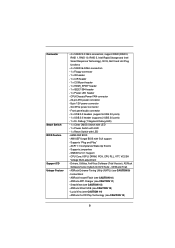
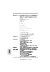
...GUI support - CPU Core, IGPU, DRAM, PCH, CPU PLL, VTT, VCCSA Voltage Multi-adjustment - ASRock APP Charger (see CAUTION 10) - ASRock Instant Flash (see CAUTION 11) - ASRock On/Off Play Technology (see CAUTION 9) - ACPI 1.1 Compliance Wake Up Events - SMBIOS 2.3.1 Support ...15) 8 SmartView (see CAUTION 13) - Instant Boot - Drivers, Utilities, AntiVirus Software (Trial Version), ASRock Software Suite (CyberLink DVD Suite - ASRock XFast USB (see CAUTION 12) - SLI/XFire power connector - Lucid Virtu (see CAUTION 14) - Connector Smart Switch BIOS Feature Support CD Unique ...
...GUI support - CPU Core, IGPU, DRAM, PCH, CPU PLL, VTT, VCCSA Voltage Multi-adjustment - ASRock APP Charger (see CAUTION 10) - ASRock Instant Flash (see CAUTION 11) - ASRock On/Off Play Technology (see CAUTION 9) - ACPI 1.1 Compliance Wake Up Events - SMBIOS 2.3.1 Support ...15) 8 SmartView (see CAUTION 13) - Instant Boot - Drivers, Utilities, AntiVirus Software (Trial Version), ASRock Software Suite (CyberLink DVD Suite - ASRock XFast USB (see CAUTION 12) - SLI/XFire power connector - Lucid Virtu (see CAUTION 14) - Connector Smart Switch BIOS Feature Support CD Unique ...

User Manual
Page 13
.../s SATA3_0_1 SATA3_M1_M2 CHA_FAN1 Designed in Taipei SLI/XFIRE_PWR1 Top: SIDE SPK Center: REAR SPK FRONT Bottom: Optical SPDIF Top: LINE IN Center: Bottom: MIC IN 45 44 43 42 41 40 39 38 37 HDMI 1.4a CHA_FAN3 CHA_FAN2 USB 3.0 PCIE1 Z68 Extreme4 PCIE2 DX10.1 LAN PHY PCIE3 PCI... Express 2.0 Super I/O PCI1 ErP/EuP Ready PCIE4 CMOS Battery 1 CLRCMOS1 Intel Z68 64Mb BIOS SATA2_4_5 SATA2_2_3 AUDIO CODEC RoHS HD_AUDIO1 1 HDMI_SPDIF1 COM1 1 1 PCI2 Front USB ...
.../s SATA3_0_1 SATA3_M1_M2 CHA_FAN1 Designed in Taipei SLI/XFIRE_PWR1 Top: SIDE SPK Center: REAR SPK FRONT Bottom: Optical SPDIF Top: LINE IN Center: Bottom: MIC IN 45 44 43 42 41 40 39 38 37 HDMI 1.4a CHA_FAN3 CHA_FAN2 USB 3.0 PCIE1 Z68 Extreme4 PCIE2 DX10.1 LAN PHY PCIE3 PCI... Express 2.0 Super I/O PCI1 ErP/EuP Ready PCIE4 CMOS Battery 1 CLRCMOS1 Intel Z68 64Mb BIOS SATA2_4_5 SATA2_2_3 AUDIO CODEC RoHS HD_AUDIO1 1 HDMI_SPDIF1 COM1 1 1 PCI2 Front USB ...

User Manual
Page 25
... item, please select Enabled. And click Apply. After that, you can freely enjoy the bene t of SLITM feature. 25 In Select an SLI configuration item, please select Enable SLI. Reboot your Windows® taskbar. B. D. You can enable the MultiGraphics Processing Unit (GPU) feature in the NVIDIA® nView system tray... the graphics card drivers to enable the multi-GPU feature. C. Please follow the below procedures to your system. From the pop-up menu, select Set SLI and PhysX configuration.
... item, please select Enabled. And click Apply. After that, you can freely enjoy the bene t of SLITM feature. 25 In Select an SLI configuration item, please select Enable SLI. Reboot your Windows® taskbar. B. D. You can enable the MultiGraphics Processing Unit (GPU) feature in the NVIDIA® nView system tray... the graphics card drivers to enable the multi-GPU feature. C. Please follow the below procedures to your system. From the pop-up menu, select Set SLI and PhysX configuration.

User Manual
Page 26
... the Start icon on your system. D. From the pop-up menu, select All Programs, and then click NVIDIA Corporation. In Select an SLI configuration item, please select Enable SLI. Select NVIDIA Control Panel tab. F. Reboot your Windows taskbar. For Windows® VistaTM / VistaTM 64-bit / 7 / 7 64-bit... OS: (For SLITM and Quad SLITM mode) A. G. From the pop-up menu, select Set SLI and PhysX configuration. E. And click Apply. Select Control Panel tab. B. In Set PhysX GPU acceleration item, please select Enabled.
... the Start icon on your system. D. From the pop-up menu, select All Programs, and then click NVIDIA Corporation. In Select an SLI configuration item, please select Enable SLI. Select NVIDIA Control Panel tab. F. Reboot your Windows taskbar. For Windows® VistaTM / VistaTM 64-bit / 7 / 7 64-bit... OS: (For SLITM and Quad SLITM mode) A. G. From the pop-up menu, select Set SLI and PhysX configuration. E. And click Apply. Select Control Panel tab. B. In Set PhysX GPU acceleration item, please select Enabled.

User Manual
Page 42
To use this connector, but please connect it with Pin 1 and Pin 5. 8 5 4-Pin ATX 12V Power Supply Installation 4 1 SLI/XFIRE Power Connector (4-pin SLI/XFIRE_PWR1) (see p.13 No. 1) 8 5 4 1 Please connect an ATX 12V power supply to this motherboard. 42 To use the 4-pin ATX power supply, please ... along with Pin 1 and Pin 13. 20-Pin ATX Power Supply Installation 1 13 ATX 12V Power Connector (8-pin ATX12V1) (see p.13 No. 45) SLI/XFIRE_POWER1 It is not necessary to use the 20-pin ATX power supply, please plug your power supply along with a hard disk power connecor when...
To use this connector, but please connect it with Pin 1 and Pin 5. 8 5 4-Pin ATX 12V Power Supply Installation 4 1 SLI/XFIRE Power Connector (4-pin SLI/XFIRE_PWR1) (see p.13 No. 1) 8 5 4 1 Please connect an ATX 12V power supply to this motherboard. 42 To use the 4-pin ATX power supply, please ... along with Pin 1 and Pin 13. 20-Pin ATX Power Supply Installation 1 13 ATX 12V Power Connector (8-pin ATX12V1) (see p.13 No. 45) SLI/XFIRE_POWER1 It is not necessary to use the 20-pin ATX power supply, please plug your power supply along with a hard disk power connecor when...

Quick Installation Guide
Page 2
...SATA3_M1_M2 CHA_FAN1 Designed in Taipei SLI/XFIRE_PWR1 Top: SIDE SPK Center: REAR SPK FRONT Bottom: Optical SPDIF Top: LINE IN Center: Bottom: MIC IN 45 44 43 42 41 40 39 38 37 HDMI 1.4a CHA_FAN3 CHA_FAN2 USB 3.0 PCIE1 Z68 Extreme4 PCIE2 DX10.1 LAN PHY ...44 PCI Express 2.0 x1 Slot (PCIE1, White) 22 Power Switch (PWRBTN) 45 SLI / XFIRE Power Connector 23 Power LED Header (PLED1) 46 Chassis Fan Connector (CHA_FAN3) 24 System Panel Header (PANEL1, White) 47 Chassis Fan Connector (CHA_FAN2) 25 Chassis Speaker Header (SPEAKER 1, White) 2 ASRock Z68 Extreme4 Motherboard English
...SATA3_M1_M2 CHA_FAN1 Designed in Taipei SLI/XFIRE_PWR1 Top: SIDE SPK Center: REAR SPK FRONT Bottom: Optical SPDIF Top: LINE IN Center: Bottom: MIC IN 45 44 43 42 41 40 39 38 37 HDMI 1.4a CHA_FAN3 CHA_FAN2 USB 3.0 PCIE1 Z68 Extreme4 PCIE2 DX10.1 LAN PHY ...44 PCI Express 2.0 x1 Slot (PCIE1, White) 22 Power Switch (PWRBTN) 45 SLI / XFIRE Power Connector 23 Power LED Header (PLED1) 46 Chassis Fan Connector (CHA_FAN3) 24 System Panel Header (PANEL1, White) 47 Chassis Fan Connector (CHA_FAN2) 25 Chassis Speaker Header (SPEAKER 1, White) 2 ASRock Z68 Extreme4 Motherboard English
Quick Installation Guide
Page 8
...VCCSA Voltage Multi-adjustment - Instant Boot - ASRock XFast USB (see CAUTION 15) English 8 ASRock Z68 Extreme4 Motherboard ASRock On/Off Play Technology (see CAUTION 13... HDMI_SPDIF header - 1 x IEEE 1394 header - 1 x Power LED header - Supports jumperfree - ASRock Instant Flash (see CAUTION 12) - ASRock APP Charger (see CAUTION 14) - Lucid Virtu (see CAUTION 11) - Supports "Plug and Play"... - Drivers, Utilities, AntiVirus Software (Trial Version), ASRock Software Suite (CyberLink DVD Suite - Front panel audio connector - 3 x USB 2.0 headers ...
...VCCSA Voltage Multi-adjustment - Instant Boot - ASRock XFast USB (see CAUTION 15) English 8 ASRock Z68 Extreme4 Motherboard ASRock On/Off Play Technology (see CAUTION 13... HDMI_SPDIF header - 1 x IEEE 1394 header - 1 x Power LED header - Supports jumperfree - ASRock Instant Flash (see CAUTION 12) - ASRock APP Charger (see CAUTION 14) - Lucid Virtu (see CAUTION 11) - Supports "Plug and Play"... - Drivers, Utilities, AntiVirus Software (Trial Version), ASRock Software Suite (CyberLink DVD Suite - Front panel audio connector - 3 x USB 2.0 headers ...

Quick Installation Guide
Page 20
...Step4. Reboot your Windows® taskbar. Align and insert ASRock SLI_Bridge_2S Card to enable the multi-GPU feature. In Select an SLI configuration item, please select Enable SLI. From the pop-up menu, select Set SLI and PhysX configuration. And click Apply. In ... For Windows® XP / XP 64-bit OS: (For SLITM mode only) A. Make sure ASRock SLI_Bridge_2S Card is inserted to PCIE2 slot. 2.5.2 Driver Installation and Setup Install the graphics card drivers to the monitor connector or the DVI connector of SLITM feature. 20 ASRock Z68 Extreme4 Motherboard English
...Step4. Reboot your Windows® taskbar. Align and insert ASRock SLI_Bridge_2S Card to enable the multi-GPU feature. In Select an SLI configuration item, please select Enable SLI. From the pop-up menu, select Set SLI and PhysX configuration. And click Apply. In ... For Windows® XP / XP 64-bit OS: (For SLITM mode only) A. Make sure ASRock SLI_Bridge_2S Card is inserted to PCIE2 slot. 2.5.2 Driver Installation and Setup Install the graphics card drivers to the monitor connector or the DVI connector of SLITM feature. 20 ASRock Z68 Extreme4 Motherboard English

Quick Installation Guide
Page 21
... PhysX configuration. E. In Set PhysX GPU acceleration item, please select Enabled. F. B. Select NVIDIA Control Panel tab. In Select an SLI configuration item, please select Enable SLI. G. D. And click Apply. C. Select Control Panel tab. From the pop-up menu, select All Programs, and then click NVIDIA Corporation. Click the... NVIDIA® Technologies Inc., and is used only for identification or explanation and to the owners' benefit, without intent to infringe. 21 ASRock Z68 Extreme4 Motherboard English
... PhysX configuration. E. In Set PhysX GPU acceleration item, please select Enabled. F. B. Select NVIDIA Control Panel tab. In Select an SLI configuration item, please select Enable SLI. G. D. And click Apply. C. Select Control Panel tab. From the pop-up menu, select All Programs, and then click NVIDIA Corporation. Click the... NVIDIA® Technologies Inc., and is used only for identification or explanation and to the owners' benefit, without intent to infringe. 21 ASRock Z68 Extreme4 Motherboard English

Quick Installation Guide
Page 37
... the 4-pin ATX power supply, please plug your power supply along with Pin 1 and Pin 5. 8 5 4-Pin ATX 12V Power Supply Installation 4 1 SLI/XFIRE Power Connector (4-pin SLI/XFIRE_PWR1) (see p.2 No. 45) SLI/XFIRE_POWER1 It is not necessary to use the 20-pin ATX power supply, please plug your power supply along with a hard... (8-pin ATX12V1) (see p.2 No. 8) 12 24 Please connect an ATX power supply to Pin 1-3. If you adopt a traditional 4-pin ATX 12V power supply. English 37 ASRock Z68 Extreme4 Motherboard
... the 4-pin ATX power supply, please plug your power supply along with Pin 1 and Pin 5. 8 5 4-Pin ATX 12V Power Supply Installation 4 1 SLI/XFIRE Power Connector (4-pin SLI/XFIRE_PWR1) (see p.2 No. 45) SLI/XFIRE_POWER1 It is not necessary to use the 20-pin ATX power supply, please plug your power supply along with a hard... (8-pin ATX12V1) (see p.2 No. 8) 12 24 Please connect an ATX power supply to Pin 1-3. If you adopt a traditional 4-pin ATX 12V power supply. English 37 ASRock Z68 Extreme4 Motherboard

Quick Installation Guide
Page 221
...- CPU CPU 한 국 어 221 ASRock Z68 Extreme4 Motherboard IEEE 1394 헤더 1 LED 헤더 1 개 - LED 1 개 - ASRock Instant Flash ( 주의 10 참조 ) - ASRock On/Off Play 15 - BIOS 지원 CD... ) - CPU 24 핀 ATX 8 핀 ATX 12V SLI/XFIRE USB 2.0 헤더 3 개 (6 USB 2.0 2개 ) - SmartView ( 주의 12 참조 ) - USB 3.0 헤더 1 개 (2 USB 3.0 2개 ) - ASRock XFast USB ( 주의 13 참조 ) - ...
...- CPU CPU 한 국 어 221 ASRock Z68 Extreme4 Motherboard IEEE 1394 헤더 1 LED 헤더 1 개 - LED 1 개 - ASRock Instant Flash ( 주의 10 참조 ) - ASRock On/Off Play 15 - BIOS 지원 CD... ) - CPU 24 핀 ATX 8 핀 ATX 12V SLI/XFIRE USB 2.0 헤더 3 개 (6 USB 2.0 2개 ) - SmartView ( 주의 12 참조 ) - USB 3.0 헤더 1 개 (2 USB 3.0 2개 ) - ASRock XFast USB ( 주의 13 참조 ) - ...

Quick Installation Guide
Page 239
...) (2 45 IEEE 1394 헤더 (9 핀 FRONT_1394) (2 32 SLI/XFIRE_POWER1 RXTPAM_0 GND RXTPBM_0 +12V GND 1 +12V RXTPBP_0 GND RXTPAP_0 (9 핀 COM1) (2 35 2 I/O 1 IEEE 1394 IEEE 1394 (FRONT_1394) 헤더가 1 IEEE 1394 헤더&#... 1 GND SPDIFOUT HDMI VGA 카드에 SPDIF HDMI_SPDIF HDMI 디지털 TV LCD HDMI VGA 카드의 HDMI_SPDIF 한국어 239 ASRock Z68 Extreme4 Motherboard
...) (2 45 IEEE 1394 헤더 (9 핀 FRONT_1394) (2 32 SLI/XFIRE_POWER1 RXTPAM_0 GND RXTPBM_0 +12V GND 1 +12V RXTPBP_0 GND RXTPAP_0 (9 핀 COM1) (2 35 2 I/O 1 IEEE 1394 IEEE 1394 (FRONT_1394) 헤더가 1 IEEE 1394 헤더&#... 1 GND SPDIFOUT HDMI VGA 카드에 SPDIF HDMI_SPDIF HDMI 디지털 TV LCD HDMI VGA 카드의 HDMI_SPDIF 한국어 239 ASRock Z68 Extreme4 Motherboard

Quick Installation Guide
Page 300
... 12 XFast USB 13) - Boot Failure Guard (B.F.G C.C.O 18 LED CPU CPU CPU CPU CPU ASRock Z68 Extreme4 Motherboard ASRock U-COP 17) - 繁體中文 BIOS 300 - 1 x IEEE 1394 接頭 - 1 x CPU 24 針 ATX 8 針 12V SLI/XFire 3 x USB 2.0 6 USB 2.0 接口 ) - 1 x USB 3.0 2 USB 3.0 接口 ) - 1 x Dr. Debug (7 LED) - 1 個 LED CMOS...
... 12 XFast USB 13) - Boot Failure Guard (B.F.G C.C.O 18 LED CPU CPU CPU CPU CPU ASRock Z68 Extreme4 Motherboard ASRock U-COP 17) - 繁體中文 BIOS 300 - 1 x IEEE 1394 接頭 - 1 x CPU 24 針 ATX 8 針 12V SLI/XFire 3 x USB 2.0 6 USB 2.0 接口 ) - 1 x USB 3.0 2 USB 3.0 接口 ) - 1 x Dr. Debug (7 LED) - 1 個 LED CMOS...