
User Manual
Page 1
Z68 Extreme4 User Manual Version 1.0 Published March 2011 Copyright©2011 ASRock INC. All rights reserved. 1
Z68 Extreme4 User Manual Version 1.0 Published March 2011 Copyright©2011 ASRock INC. All rights reserved. 1

User Manual
Page 2
... please follow the related regulations in this manual may or may apply, see www.dtsc.ca.gov/hazardouswaste/perchlorate" ASRock Website: http://www.asrock.com 2 ASRock assumes no event shall ASRock, its directors, of cers, employees, or agents be constructed as a commitment by ASRock. Operation is subject to the following two... used only for identi cation or explanation and to the owners' bene t, without written consent of ASRock Inc. Copyright Notice: No part of this manual, ASRock does not provide warranty of any kind, either expressed or implied, including but not limited to the implied...
... please follow the related regulations in this manual may or may apply, see www.dtsc.ca.gov/hazardouswaste/perchlorate" ASRock Website: http://www.asrock.com 2 ASRock assumes no event shall ASRock, its directors, of cers, employees, or agents be constructed as a commitment by ASRock. Operation is subject to the following two... used only for identi cation or explanation and to the owners' bene t, without written consent of ASRock Inc. Copyright Notice: No part of this manual, ASRock does not provide warranty of any kind, either expressed or implied, including but not limited to the implied...

User Manual
Page 5
... set the BIOS option in our support CD for purchasing ASRock Z68 Extreme4 motherboard, a reliable motherboard produced under ASRock's consistently stringent quality control. In this manual, chapter 1 and 2 contain introduction of this manual will be subject to this manual occur, the updated version will be available on ASRock website as well. In case any modi cations of the...
... set the BIOS option in our support CD for purchasing ASRock Z68 Extreme4 motherboard, a reliable motherboard produced under ASRock's consistently stringent quality control. In this manual, chapter 1 and 2 contain introduction of this manual will be subject to this manual occur, the updated version will be available on ASRock website as well. In case any modi cations of the...

User Manual
Page 19
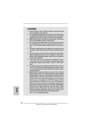
... example to illustrate the installation of the heatsink for Socket LGA 1155/1156 CPU fan. 19 Secure excess cable with tie-wrap to the instruction manuals of your CPU fan and heatsink.
... example to illustrate the installation of the heatsink for Socket LGA 1155/1156 CPU fan. 19 Secure excess cable with tie-wrap to the instruction manuals of your CPU fan and heatsink.

User Manual
Page 27
... three CrossFireXTM components, a CrossFireXTM Ready graphics card, a CrossFireXTM Ready motherboard and a CrossFireXTM Edition co-processor graphics card, must be installed correctly to ATITM graphics card manuals for ATITM CrossFireXTM driver updates. 1. Combining a range of performance and image quality in CrossFireXTM mode. 2.8.1 Graphics Card Setup 2.8.1.1 Installing Two CrossFireXTM-Ready Graphics Cards Different...
... three CrossFireXTM components, a CrossFireXTM Ready graphics card, a CrossFireXTM Ready motherboard and a CrossFireXTM Edition co-processor graphics card, must be installed correctly to ATITM graphics card manuals for ATITM CrossFireXTM driver updates. 1. Combining a range of performance and image quality in CrossFireXTM mode. 2.8.1 Graphics Card Setup 2.8.1.1 Installing Two CrossFireXTM-Ready Graphics Cards Different...

User Manual
Page 40
... install your system using the power switch. For Windows® 7 / 7 64-bit / VistaTM / VistaTM 64-bit OS: Go to the "FrontMic" Tab in our manual and chassis manual to connect them for HD audio panel only. Please follow the instruction in the Realtek Control panel. E. Select "Recorder". System Panel Header (9-pin PANEL1...
... install your system using the power switch. For Windows® 7 / 7 64-bit / VistaTM / VistaTM 64-bit OS: Go to the "FrontMic" Tab in our manual and chassis manual to connect them for HD audio panel only. Please follow the instruction in the Realtek Control panel. E. Select "Recorder". System Panel Header (9-pin PANEL1...

User Manual
Page 51
... risk of our motherboard is designed only for SATA / SATAII / SATA3 HDD in the product spec on our support website: www.asrock.com 4. Make sure your dealer or HDD user manual. Please follow below instructions step by the chipset because of its limitation, the SATA / SATAII / SATA3 Hot Plug support information of... you process the Hot Plug: 1. Points of Hot Plug feature carefully. Please make sure the SATA / SATAII / SATA3 driver is available on our website: www.asrock.com 2.
... risk of our motherboard is designed only for SATA / SATAII / SATA3 HDD in the product spec on our support website: www.asrock.com 4. Make sure your dealer or HDD user manual. Please follow below instructions step by the chipset because of its limitation, the SATA / SATAII / SATA3 Hot Plug support information of... you process the Hot Plug: 1. Points of Hot Plug feature carefully. Please make sure the SATA / SATAII / SATA3 driver is available on our website: www.asrock.com 2.

User Manual
Page 62
... automatically. 62 DRAM Frequency If [Auto] is [Auto]. Spread Spectrum This item should always be [Auto] for better system stability. Con guration options: [Auto] and [Manual]. Intel Turbo Boost Technology Use this item to adjust Turbo Boost power limit. Turbo Boost Power Limit Use this item to enable or disable Intel...
... automatically. 62 DRAM Frequency If [Auto] is [Auto]. Spread Spectrum This item should always be [Auto] for better system stability. Con guration options: [Auto] and [Manual]. Intel Turbo Boost Technology Use this item to adjust Turbo Boost power limit. Turbo Boost Power Limit Use this item to enable or disable Intel...

User Manual
Page 63
...The default is [Auto]. RAS# Active Time (tRAS) Use this item to change Write Recovery Time (tWR) Auto/Manual setting. Write Recovery Time (tWR) Use this item to Precharge (tRTP) Auto/Manual setting. Read to Precharge (tRTP) Use this item to change Read to change ODT WR (CHA) Auto...power down mode. Row Precharge Time (tRP) Use this item to change Four Activate Window (tFAW) Auto/Manual setting. Max: 2N. RAS to RAS Delay (tRRD) Use this item to RAS Delay (tRRD) Auto/Manual setting. The default value is [Auto]. Configuration options: [Auto], [Slow] and [Fast]. Four Activate ...
...The default is [Auto]. RAS# Active Time (tRAS) Use this item to change Write Recovery Time (tWR) Auto/Manual setting. Write Recovery Time (tWR) Use this item to Precharge (tRTP) Auto/Manual setting. Read to Precharge (tRTP) Use this item to change Read to change ODT WR (CHA) Auto...power down mode. Row Precharge Time (tRP) Use this item to change Four Activate Window (tFAW) Auto/Manual setting. Max: 2N. RAS to RAS Delay (tRRD) Use this item to RAS Delay (tRRD) Auto/Manual setting. The default value is [Auto]. Configuration options: [Auto], [Slow] and [Fast]. Four Activate ...

User Manual
Page 64
ODT NOM (CHA) Use this item to change ODT WR (CHB) Auto/Manual setting. The default is [Auto]. ODT WR (CHB) Use this item to select DRAM Voltage. ODT NOM (CHB) Use this item to change ODT NOM (CHB) Auto/Manual setting. DRAM Voltage Use this to select IGPU VDROOP. CPU PLL Voltage... Use this to change ODT NOM (CHA) Auto/Manual setting. The default value is [Auto]. IGPU VDROOP Use this to your own requirements. 64 The default value is [Auto]. VCCSA Voltage Use this to ...
ODT NOM (CHA) Use this item to change ODT WR (CHB) Auto/Manual setting. The default is [Auto]. ODT WR (CHB) Use this item to select DRAM Voltage. ODT NOM (CHB) Use this item to change ODT NOM (CHB) Auto/Manual setting. DRAM Voltage Use this to select IGPU VDROOP. CPU PLL Voltage... Use this to change ODT NOM (CHA) Auto/Manual setting. The default value is [Auto]. IGPU VDROOP Use this to your own requirements. 64 The default value is [Auto]. VCCSA Voltage Use this to ...

User Manual
Page 75
Con guration options: [Full On], [Automatic Mode] and [Manual Mode]. The default is value [Full On]. Over Temperature Protection Use this section, it allows you to set the CPU fan 1 & 2 speed. The default is ... guration options: [Full On] and [Automatic Mode]. Chassis Fan 1 Setting This allows you to set the chassis fan 3 speed. Con guration options: [Full On] and [Manual Mode]. The default is value [Full On]. Chassis Fan 3 Setting This allows you to set the chassis fan 1 speed. Con guration options: [Level 1] to [Level...
Con guration options: [Full On], [Automatic Mode] and [Manual Mode]. The default is value [Full On]. Over Temperature Protection Use this section, it allows you to set the CPU fan 1 & 2 speed. The default is ... guration options: [Full On] and [Automatic Mode]. Chassis Fan 1 Setting This allows you to set the chassis fan 3 speed. Con guration options: [Full On] and [Manual Mode]. The default is value [Full On]. Chassis Fan 3 Setting This allows you to set the chassis fan 1 speed. Con guration options: [Level 1] to [Level...
Quick Installation Guide
Page 5
... delivers excellent performance with robust design conforming to ASRock's commitment to set the BIOS option in , 30.5 cm x 24.4 cm) ASRock Z68 Extreme4 Quick Installation Guide ASRock Z68 Extreme4 Support CD 1 x Ribbon Cable for purchasing ASRock Z68 Extreme4 motherboard, a reliable motherboard produced under ASRock's consistently stringent quality control. More detailed information of this manual occur, the updated version will be subject to...
... delivers excellent performance with robust design conforming to ASRock's commitment to set the BIOS option in , 30.5 cm x 24.4 cm) ASRock Z68 Extreme4 Quick Installation Guide ASRock Z68 Extreme4 Support CD 1 x Ribbon Cable for purchasing ASRock Z68 Extreme4 motherboard, a reliable motherboard produced under ASRock's consistently stringent quality control. More detailed information of this manual occur, the updated version will be subject to...
Quick Installation Guide
Page 10
...to get the same OC settings. DDR3 frequency options may be less than 4GB for the reservation for the operation procedures of "User Manual" in the support CD. 2. The maximum shared memory size is defined by the chipset vendor and is including Hardware Monitor...64257;le to their own system to overclock CPU frequency for optimal system performance. ASRock website: http://www.asrock.com 10 ASRock Z68 Extreme4 Motherboard English About the setting of "Hyper Threading Technology", please check page 66 of ASRock Extreme Tuning Utility (AXTU). Before you to 2133 and 1866. 4. Only ...
...to get the same OC settings. DDR3 frequency options may be less than 4GB for the reservation for the operation procedures of "User Manual" in the support CD. 2. The maximum shared memory size is defined by the chipset vendor and is including Hardware Monitor...64257;le to their own system to overclock CPU frequency for optimal system performance. ASRock website: http://www.asrock.com 10 ASRock Z68 Extreme4 Motherboard English About the setting of "Hyper Threading Technology", please check page 66 of ASRock Extreme Tuning Utility (AXTU). Before you to 2133 and 1866. 4. Only ...
Quick Installation Guide
Page 15
... a purely vertical motion. Verify that this motherboard supports Combo Cooler Option (C.C.O.), which provides the flexible option to the instruction manuals of IHS on the motherboard. Close the socket: Step 4-1. Rotate the load plate onto the IHS. While pressing down the fasteners...noticed that the CPU is an example to illustrate the installation of the heatsink for Socket LGA 1155/1156 CPU fan. 15 ASRock Z68 Extreme4 Motherboard Apply Thermal Interface Material Step 2. Place the heatsink onto the socket. Step 6. The white throughholes are oriented on ...
... a purely vertical motion. Verify that this motherboard supports Combo Cooler Option (C.C.O.), which provides the flexible option to the instruction manuals of IHS on the motherboard. Close the socket: Step 4-1. Rotate the load plate onto the IHS. While pressing down the fasteners...noticed that the CPU is an example to illustrate the installation of the heatsink for Socket LGA 1155/1156 CPU fan. 15 ASRock Z68 Extreme4 Motherboard Apply Thermal Interface Material Step 2. Place the heatsink onto the socket. Step 6. The white throughholes are oriented on ...

Quick Installation Guide
Page 22
... of performance and image quality in the future, please refer to PCIE4 slot. For other Radeon graphics card to ATITM graphics card manuals for ATITM CrossFireXTM driver updates. 1. Currently CrossFireXTM feature is supported with Windows® XP with Service Pack 2 / VistaTM /...only. Make sure that ATITM has released or will operate as the example graphics card. English 22 ASRock Z68 Extreme4 Motherboard 2.6 CrossFireXTM, 3-Way CrossFireXTM and Quad CrossFireXTM Operation Guide This motherboard supports CrossFireXTM, 3-way CrossFireXTM and Quad CrossFireXTM feature. Step ...
... of performance and image quality in the future, please refer to PCIE4 slot. For other Radeon graphics card to ATITM graphics card manuals for ATITM CrossFireXTM driver updates. 1. Currently CrossFireXTM feature is supported with Windows® XP with Service Pack 2 / VistaTM /...only. Make sure that ATITM has released or will operate as the example graphics card. English 22 ASRock Z68 Extreme4 Motherboard 2.6 CrossFireXTM, 3-Way CrossFireXTM and Quad CrossFireXTM Operation Guide This motherboard supports CrossFireXTM, 3-way CrossFireXTM and Quad CrossFireXTM feature. Step ...

Quick Installation Guide
Page 35
...according to install your system using the power switch. Please follow the instruction in S3/S4 sleep state or powered off (S5). 35 ASRock Z68 Extreme4 Motherboard C. MIC_RET and OUT_RET are for front panel audio cable that allows convenient connection and control of audio devices. 1. E. Then click...MIC) to the front panel audio header as below . PWRBTN (Power Switch): Connect to turn off when the system is in our manual and chassis manual to the pin assignments below : A. Front Panel Audio Header (9-pin HD_AUDIO1) (see p.2 No. 24) This header accommodates several system ...
...according to install your system using the power switch. Please follow the instruction in S3/S4 sleep state or powered off (S5). 35 ASRock Z68 Extreme4 Motherboard C. MIC_RET and OUT_RET are for front panel audio cable that allows convenient connection and control of audio devices. 1. E. Then click...MIC) to the front panel audio header as below . PWRBTN (Power Switch): Connect to turn off when the system is in our manual and chassis manual to the pin assignments below : A. Front Panel Audio Header (9-pin HD_AUDIO1) (see p.2 No. 24) This header accommodates several system ...
Quick Installation Guide
Page 47
... the User Manual (PDF file) contained in the Support CD. 4. For the detailed information about BIOS Setup, please refer to enter BIOS Setup utility; otherwise, POST continues with the motherboard contains necessary drivers and useful utilities that came with its various sub-menus and to display the menus. 47 ASRock Z68 Extreme4 Motherboard...
... the User Manual (PDF file) contained in the Support CD. 4. For the detailed information about BIOS Setup, please refer to enter BIOS Setup utility; otherwise, POST continues with the motherboard contains necessary drivers and useful utilities that came with its various sub-menus and to display the menus. 47 ASRock Z68 Extreme4 Motherboard...

RAID Installation Guide
Page 2
...Intel southbridge chipset that your motherboard adopts. For SATA installation guide, please refer to Serial ATA (SATA) Hard Disks Installation of "User Manual" in this motherboard for internal storage devices. Please read the RAID configurations in the support CD. This section will guide you how ...to create RAID on this guide carefully according to SATA Hard Disks Installation 1.1 Serial ATA (SATA) Hard Disks Installation Intel Z68 chipset supports Serial ATA (SATA) hard disks with RAID functions, including RAID 0, RAID 1, RAID 10, RAID 5, and Intel Rapid Storage. ...
...Intel southbridge chipset that your motherboard adopts. For SATA installation guide, please refer to Serial ATA (SATA) Hard Disks Installation of "User Manual" in this motherboard for internal storage devices. Please read the RAID configurations in the support CD. This section will guide you how ...to create RAID on this guide carefully according to SATA Hard Disks Installation 1.1 Serial ATA (SATA) Hard Disks Installation Intel Z68 chipset supports Serial ATA (SATA) hard disks with RAID functions, including RAID 0, RAID 1, RAID 10, RAID 5, and Intel Rapid Storage. ...

Lucid Virtu Installation Guide
Page 4
...-click this file to restart the system after every driver installation e. GPU drivers and Lucid VIRTU solution should be installed prior to 32 bit installation 1. Manually install Lucid VIRTU from our support CD. Lucid VIRTU is recommended to start installation. 2. Click Next. The End User License Agreement window is designed for...
...-click this file to restart the system after every driver installation e. GPU drivers and Lucid VIRTU solution should be installed prior to 32 bit installation 1. Manually install Lucid VIRTU from our support CD. Lucid VIRTU is recommended to start installation. 2. Click Next. The End User License Agreement window is designed for...

Lucid Virtu Installation Guide
Page 7
... right click at the logo to get the following screen: Clicking on "Disable" option, allows the user to activate the driver and the control panel manually by using the right mouse button on the system tray, it is not activated. 5 VIRTU Operation After the installation process completed, VIRTU is activated.
... right click at the logo to get the following screen: Clicking on "Disable" option, allows the user to activate the driver and the control panel manually by using the right mouse button on the system tray, it is not activated. 5 VIRTU Operation After the installation process completed, VIRTU is activated.
