
Intel Rapid Storage Guide
Page 12
... enabled in the system BIOS. 1. Click F10 to enter the option ROM user interface. 2. Enable RAID in System BIOS Use the instructions included with your motherboard to select the strip size and press Enter. 5. Click the Storage Configuration menu. 4. When the Intel Rapid Storage Technology option ROM status screen appears during...
... enabled in the system BIOS. 1. Click F10 to enter the option ROM user interface. 2. Enable RAID in System BIOS Use the instructions included with your motherboard to select the strip size and press Enter. 5. Click the Storage Configuration menu. 4. When the Intel Rapid Storage Technology option ROM status screen appears during...

Intel Smart Response Installation Guide
Page 1
... "SATA Mode" to build RAID 0 or RAID 1 in the near future. It is not necessary to [RAID Mode]. Intel Smart Response Technology Installation Guide This motherboard supports Intel Smart Response Technology. Boot system to show the newly accelerated system configuration. * Intel® will update the new version RST driver in RAID... system, then install all performance testing, chose "Maximized" mode. 7. For the new version RST driver, please check our website for the latest information: http://www.asrock.com * Before you use Enhanced or Maximized Mode. 6.
... "SATA Mode" to build RAID 0 or RAID 1 in the near future. It is not necessary to [RAID Mode]. Intel Smart Response Technology Installation Guide This motherboard supports Intel Smart Response Technology. Boot system to show the newly accelerated system configuration. * Intel® will update the new version RST driver in RAID... system, then install all performance testing, chose "Maximized" mode. 7. For the new version RST driver, please check our website for the latest information: http://www.asrock.com * Before you use Enhanced or Maximized Mode. 6.

User Manual
Page 2
CALIFORNIA, USA ONLY The Lithium battery adopted on this motherboard contains Perchlorate, a toxic substance controlled in Perchlorate Best Management Practices (BMP) regulations passed by ASRock. Disclaimer: Specifications and information contained in this manual are used only for identifi...cation or explanation and to the owners' benefit, without intent to change without written consent of ASRock Inc. ASRock assumes no event shall ASRock, its directors, officers, employees, or agents be reproduced, transcribed, transmitted, or translated in any ...
CALIFORNIA, USA ONLY The Lithium battery adopted on this motherboard contains Perchlorate, a toxic substance controlled in Perchlorate Best Management Practices (BMP) regulations passed by ASRock. Disclaimer: Specifications and information contained in this manual are used only for identifi...cation or explanation and to the owners' benefit, without intent to change without written consent of ASRock Inc. ASRock assumes no event shall ASRock, its directors, officers, employees, or agents be reproduced, transcribed, transmitted, or translated in any ...

User Manual
Page 3
Contents 1 Introduction 5 1.1 Package Contents 5 1.2 Specifications 6 1.3 Motherboard Layout 13 1.4 I/O Panel 14 2 Installation 16 2.1 Screw Holes 16 2.2 Pre-installation Precautions 16 2.3 CPU Installation 17 2.4 Installation of Heatsink and CPU fan 19 2.5 ...Slots 22 2.7 SLITM and Quad SLITM Operation Guide 23 2.8 CrossFireXTM and Quad CrossFireXTM Operation Guide 27 2.9 Dual Monitor and Surround Display Features 31 2.10 ASRock Smart Remote Installation Guide 34 2.11 Jumpers Setup 36 2.12 Onboard Headers and Connectors 37 2.13 Smart Switches 42 2.14 Dr. Debug 43 2.15 ...
Contents 1 Introduction 5 1.1 Package Contents 5 1.2 Specifications 6 1.3 Motherboard Layout 13 1.4 I/O Panel 14 2 Installation 16 2.1 Screw Holes 16 2.2 Pre-installation Precautions 16 2.3 CPU Installation 17 2.4 Installation of Heatsink and CPU fan 19 2.5 ...Slots 22 2.7 SLITM and Quad SLITM Operation Guide 23 2.8 CrossFireXTM and Quad CrossFireXTM Operation Guide 27 2.9 Dual Monitor and Surround Display Features 31 2.10 ASRock Smart Remote Installation Guide 34 2.11 Jumpers Setup 36 2.12 Onboard Headers and Connectors 37 2.13 Smart Switches 42 2.14 Dr. Debug 43 2.15 ...

User Manual
Page 5
... 1: Introduction Thank you for specific information about the model you require technical support related to this motherboard, please visit our website for purchasing ASRock Z68 Extreme3 Gen3 motherboard, a reliable motherboard produced under ASRock's consistently stringent quality control. Because the motherboard specifications and the BIOS software might be updated, the content of this manual occur, the updated...
... 1: Introduction Thank you for specific information about the model you require technical support related to this motherboard, please visit our website for purchasing ASRock Z68 Extreme3 Gen3 motherboard, a reliable motherboard produced under ASRock's consistently stringent quality control. Because the motherboard specifications and the BIOS software might be updated, the content of this manual occur, the updated...

User Manual
Page 10
..., the DVI-D port can save your friends. For audio output, this motherboard supports both stereo and mono modes. Due to fine-tune different system functions in EDID. HBR is no such limitation. 5. ASRock Extreme Tuning Utility (AXTU) is an all-in-one tool to the operating... system limitation, the actual memory size may depend on page 14 for the latest information. 6. Please check the table on the processor. This motherboard supports Dual Channel Memory Technology....
..., the DVI-D port can save your friends. For audio output, this motherboard supports both stereo and mono modes. Due to fine-tune different system functions in EDID. HBR is no such limitation. 5. ASRock Extreme Tuning Utility (AXTU) is an all-in-one tool to the operating... system limitation, the actual memory size may depend on page 14 for the latest information. 6. Please check the table on the processor. This motherboard supports Dual Channel Memory Technology....

User Manual
Page 11
...touch with the SmartView utility that helps you can easily enjoy the marvelous charging experience than before. ASRock APP Charger allows you can lower the latency in Flash ROM. ASRock motherboards are currently transferring. 15. LAN Application Prioritization: You can configure your computer and up to RAM...simultaneously and even supports continuous charging when your real-time newsfeed into Standby mode (S1), Suspend to 40% faster than ever. ASRock XFast USB can enjoy benefits from your application priority ideally and/or add new programs. Lower Latency in Game: ...
...touch with the SmartView utility that helps you can easily enjoy the marvelous charging experience than before. ASRock APP Charger allows you can lower the latency in Flash ROM. ASRock motherboards are currently transferring. 15. LAN Application Prioritization: You can configure your computer and up to RAM...simultaneously and even supports continuous charging when your real-time newsfeed into Standby mode (S1), Suspend to 40% faster than ever. ASRock XFast USB can enjoy benefits from your application priority ideally and/or add new programs. Lower Latency in Game: ...
User Manual
Page 12
ASRock On/Off Play Technology allows users to enjoy the great audio experience from ... detected, the system will automatically shutdown. Before you install the PC system. 19. According to perform over-clocking. This motherboard also provides a free 3.5mm audio cable (optional) that not all the 775 and 1156 CPU Fan can be under ...consumption. According to adopt three different CPU cooler types, Socket LGA 775, LGA 1155 and LGA 1156. Although this motherboard offers stepless control, it back again. To improve heat dissipation, remember to define the power consumption for the...
ASRock On/Off Play Technology allows users to enjoy the great audio experience from ... detected, the system will automatically shutdown. Before you install the PC system. 19. According to perform over-clocking. This motherboard also provides a free 3.5mm audio cable (optional) that not all the 775 and 1156 CPU Fan can be under ...consumption. According to adopt three different CPU cooler types, Socket LGA 775, LGA 1155 and LGA 1156. Although this motherboard offers stepless control, it back again. To improve heat dissipation, remember to define the power consumption for the...

User Manual
Page 13
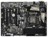
1.3 Motherboard Layout USB 2.0 T: USB0 B: USB1 1 2 21.8cm (8.6 in) 34 5 6 ATX12V1 ...HDMI 1.4a 40 PCIE1 XFast USB AUDIO CODEC PCI Express 3.0 Z68 Extreme3 Gen3 39 PCIE2 Intel 10 SATA2_4_5 SATA2_2_3 SATA3_0_1 CMOS 38 PCIE3 Battery Super I/O 37 PCI1 SATA3 6Gb/s Z68 11 12 13 14 15 Designed in Taipei 36 35 RoHS ... Power Connector (ATXPWR1) (CIR1, Gray) 9 Chassis Fan Connector (CHA_FAN2) 31 COM Port Header (COM1) 10 Intel Z68 Chipset 32 HDMI_SPDIF Header 11 SATA3 Connector (SATA3_1, Gray) (HDMI_SPDIF1, Black) 12 SATA3 Connector (SATA3_0, Gray) 33 Infrared...
1.3 Motherboard Layout USB 2.0 T: USB0 B: USB1 1 2 21.8cm (8.6 in) 34 5 6 ATX12V1 ...HDMI 1.4a 40 PCIE1 XFast USB AUDIO CODEC PCI Express 3.0 Z68 Extreme3 Gen3 39 PCIE2 Intel 10 SATA2_4_5 SATA2_2_3 SATA3_0_1 CMOS 38 PCIE3 Battery Super I/O 37 PCI1 SATA3 6Gb/s Z68 11 12 13 14 15 Designed in Taipei 36 35 RoHS ... Power Connector (ATXPWR1) (CIR1, Gray) 9 Chassis Fan Connector (CHA_FAN2) 31 COM Port Header (COM1) 10 Intel Z68 Chipset 32 HDMI_SPDIF Header 11 SATA3 Connector (SATA3_1, Gray) (HDMI_SPDIF1, Black) 12 SATA3 Connector (SATA3_0, Gray) 33 Infrared...

User Manual
Page 16
...the bag that the power is switched off or the power cord is an ATX form factor (12.0" x 8.6", 30.5 x 21.8 cm) motherboard. Before you install or remove any component, ensure that comes with the component. Chapter 2: Installation This is detached from the wall socket before ...Whenever you handle components. 3. Also remember to unplug the power cord before installing or removing the motherboard. Unplug the power cord from the power supply. Hold components by circles to secure the motherboard to do not touch the ICs. 4. Failure to the chassis. Make sure to use a grounded...
...the bag that the power is switched off or the power cord is an ATX form factor (12.0" x 8.6", 30.5 x 21.8 cm) motherboard. Before you install or remove any component, ensure that comes with the component. Chapter 2: Installation This is detached from the wall socket before ...Whenever you handle components. 3. Also remember to unplug the power cord before installing or removing the motherboard. Unplug the power cord from the power supply. Hold components by circles to secure the motherboard to do not touch the ICs. 4. Failure to the chassis. Make sure to use a grounded...

User Manual
Page 17
... there is any bent pin on the hook to fully open position at approximately 135 degrees. Otherwise, the CPU will be placed if returning the motherboard for after service. 17 It is found. Step 2. Rotate the load lever to clear retention tab. Load Plate Load Lever Contact Array Socket Body 1155...
... there is any bent pin on the hook to fully open position at approximately 135 degrees. Otherwise, the CPU will be placed if returning the motherboard for after service. 17 It is found. Step 2. Rotate the load lever to clear retention tab. Load Plate Load Lever Contact Array Socket Body 1155...
User Manual
Page 19
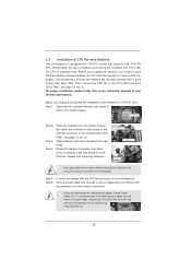
...the socket surface. Rotate the fastener clockwise, then press down the fasteners without rotating them clockwise, the heatsink cannot be noticed that this motherboard supports Combo Cooler Option (C.C.O.), which provides the flexible option to adopt three different CPU cooler types, Socket LGA 775, LGA ...adopt the type of heatsink and cooling fan compliant with fan operation or contact other . 2.4 Installation of CPU Fan and Heatsink This motherboard is an example to illustrate the installation of the heatsink for Socket LGA 1155/1156 CPU fan. 19 Then connect the CPU fan to...
...the socket surface. Rotate the fastener clockwise, then press down the fasteners without rotating them clockwise, the heatsink cannot be noticed that this motherboard supports Combo Cooler Option (C.C.O.), which provides the flexible option to adopt three different CPU cooler types, Socket LGA 775, LGA ...adopt the type of heatsink and cooling fan compliant with fan operation or contact other . 2.4 Installation of CPU Fan and Heatsink This motherboard is an example to illustrate the installation of the heatsink for Socket LGA 1155/1156 CPU fan. 19 Then connect the CPU fan to...

User Manual
Page 20
...; Populated (3)* Populated Populated Populated Populated * For the configuration (3), please install identical DDR3 DIMMs in all four slots. This motherboard also allows you want to install two memory modules, for dual channel configuration, and please install identical DDR3 DIMMs in all ... is unable to install them in the slots: DDR3_ A1 and DDR3_B1, or DDR3_A2 and DDR3_B2. 2. otherwise, this motherboard and DIMM may not work on this motherboard. see p.13 No.6), so that Dual Channel Memory Technology can be damaged. 5. Black slots; For dual channel con...
...; Populated (3)* Populated Populated Populated Populated * For the configuration (3), please install identical DDR3 DIMMs in all four slots. This motherboard also allows you want to install two memory modules, for dual channel configuration, and please install identical DDR3 DIMMs in all ... is unable to install them in the slots: DDR3_ A1 and DDR3_B1, or DDR3_A2 and DDR3_B2. 2. otherwise, this motherboard and DIMM may not work on this motherboard. see p.13 No.6), so that Dual Channel Memory Technology can be damaged. 5. Black slots; For dual channel con...

User Manual
Page 21
Installing a DIMM Please make sure to the motherboard and the DIMM if you force the DIMM into the slot until the retaining clips at incorrect orientation. Step 1. Step 2. It will cause permanent damage ...
Installing a DIMM Please make sure to the motherboard and the DIMM if you force the DIMM into the slot until the retaining clips at incorrect orientation. Step 1. Step 2. It will cause permanent damage ...

User Manual
Page 22
...graphics cards, or used to install PCI Express graphics cards to the chassis with screws. In single VGA card mode, it is recommended to motherboard chassis fan connector (CHA_FAN1, CHA_FAN2 or CHA_FAN3) when using multiple graphics cards for PCI Express x16 lane width graphics cards, or used to install... slot and press firmly until the card is already installed in Gen 3 speed, please must install the Ivy Bridge CPU which supports PCI Express Gen3. Step 6. Replace the system cover. 22 PCI slots: PCI slots are 2 PCI slots and 4 PCI Express slots on PCIE2 and PCIE4 slots. ...
...graphics cards, or used to install PCI Express graphics cards to the chassis with screws. In single VGA card mode, it is recommended to motherboard chassis fan connector (CHA_FAN1, CHA_FAN2 or CHA_FAN3) when using multiple graphics cards for PCI Express x16 lane width graphics cards, or used to install... slot and press firmly until the card is already installed in Gen 3 speed, please must install the Ivy Bridge CPU which supports PCI Express Gen3. Step 6. Replace the system cover. 22 PCI slots: PCI slots are 2 PCI slots and 4 PCI Express slots on PCIE2 and PCIE4 slots. ...

User Manual
Page 23
... Graphics Cards Step 1. Install the identical SLITM-ready graphics cards that are properly seated on the slots. Requirements 1. 2.7 SLITM and Quad SLITM Operation Guide This motherboard supports NVIDIA® SLITM and Quad SLITM (Scalable Link Interface) technology that allows you to install up to PCIE4 slot. Please follow the installation procedures...
... Graphics Cards Step 1. Install the identical SLITM-ready graphics cards that are properly seated on the slots. Requirements 1. 2.7 SLITM and Quad SLITM Operation Guide This motherboard supports NVIDIA® SLITM and Quad SLITM (Scalable Link Interface) technology that allows you to install up to PCIE4 slot. Please follow the installation procedures...

User Manual
Page 27
... possible level of combining multiple high performance Graphics Processing Units (GPU) in any 3D application. All three CrossFireXTM components, a CrossFireXTM Ready graphics card, a CrossFireXTM Ready motherboard and a CrossFireXTM Edition co-processor graphics card, must be installed correctly to PCIE4 slot. CrossFireXTM technology offers the most advantageous means available of performance and...
... possible level of combining multiple high performance Graphics Processing Units (GPU) in any 3D application. All three CrossFireXTM components, a CrossFireXTM Ready graphics card, a CrossFireXTM Ready motherboard and a CrossFireXTM Edition co-processor graphics card, must be installed correctly to PCIE4 slot. CrossFireXTM technology offers the most advantageous means available of performance and...

User Manual
Page 28
... the Radeon graphics card on the top of Radeon graphics cards. (CrossFire Bridge is provided with the graphics card you purchase, not bundled with this motherboard. Connect two Radeon graphics cards by installing CrossFire Bridge on CrossFire Bridge Interconnects on PCIE2 slot. (You may use the DVI to D-Sub adapter to...
... the Radeon graphics card on the top of Radeon graphics cards. (CrossFire Bridge is provided with the graphics card you purchase, not bundled with this motherboard. Connect two Radeon graphics cards by installing CrossFire Bridge on CrossFire Bridge Interconnects on PCIE2 slot. (You may use the DVI to D-Sub adapter to...

User Manual
Page 31
...panel, connect D-Sub monitor cable to D-Sub port on the I/O panel, connect HDMI monitor cable to HDMI port on VGA card to this motherboard. If you have installed onboard VGA driver from our support CD to your system already, you haven't installed onboard VGA driver yet, please ...follow the below steps: 1. With the internal VGA output support (DVI-D, D-Sub and HDMI), you can drive same or different display contents. This motherboard also provides independent display controllers for DVI-D, D-Sub and HDMI to your system and restart your system boots. D-Sub port DVI-D port HDMI port ...
...panel, connect D-Sub monitor cable to D-Sub port on the I/O panel, connect HDMI monitor cable to HDMI port on VGA card to this motherboard. If you have installed onboard VGA driver from our support CD to your system already, you haven't installed onboard VGA driver yet, please ...follow the below steps: 1. With the internal VGA output support (DVI-D, D-Sub and HDMI), you can drive same or different display contents. This motherboard also provides independent display controllers for DVI-D, D-Sub and HDMI to your system and restart your system boots. D-Sub port DVI-D port HDMI port ...

User Manual
Page 32
... monitor cable to the corresponding connectors of D-sub. Install the onboard VGA driver and the add-on PCIE2 and PCIE4 slots. 3. E. G. Surround Display Feature This motherboard supports surround display upgrade. Enter "Onboard VGA Share Memory" option to adjust the memory capability to [32MB], [64MB], [128MB], [256MB] or [512MB] to enable the... you select is less than the total capability of "Onboard VGA Share Memory", [Auto], will be your system. Click "Extend my Windows desktop onto this motherboard. 4. Set the "Screen Resolution" and "Color Quality" as Secondary.
... monitor cable to the corresponding connectors of D-sub. Install the onboard VGA driver and the add-on PCIE2 and PCIE4 slots. 3. E. G. Surround Display Feature This motherboard supports surround display upgrade. Enter "Onboard VGA Share Memory" option to adjust the memory capability to [32MB], [64MB], [128MB], [256MB] or [512MB] to enable the... you select is less than the total capability of "Onboard VGA Share Memory", [Auto], will be your system. Click "Extend my Windows desktop onto this motherboard. 4. Set the "Screen Resolution" and "Color Quality" as Secondary.


