
User Manual
Page 3
Contents 1 Introduction 5 1.1 Package Contents 5 1.2 Specifications 6 1.3 Motherboard Layout 13 1.4 I/O Panel 14 2 Installation 16 2.1 Screw Holes 16 2.2 Pre-installation Precautions 16 2.3 CPU Installation 17 2.4 Installation of Heatsink and CPU fan 19 2.5 ...Slots 22 2.7 SLITM and Quad SLITM Operation Guide 23 2.8 CrossFireXTM and Quad CrossFireXTM Operation Guide 27 2.9 Dual Monitor and Surround Display Features 31 2.10 ASRock Smart Remote Installation Guide 34 2.11 Jumpers Setup 36 2.12 Onboard Headers and Connectors 37 2.13 Smart Switches 42 2.14 Dr. Debug 43 2.15...
Contents 1 Introduction 5 1.1 Package Contents 5 1.2 Specifications 6 1.3 Motherboard Layout 13 1.4 I/O Panel 14 2 Installation 16 2.1 Screw Holes 16 2.2 Pre-installation Precautions 16 2.3 CPU Installation 17 2.4 Installation of Heatsink and CPU fan 19 2.5 ...Slots 22 2.7 SLITM and Quad SLITM Operation Guide 23 2.8 CrossFireXTM and Quad CrossFireXTM Operation Guide 27 2.9 Dual Monitor and Surround Display Features 31 2.10 ASRock Smart Remote Installation Guide 34 2.11 Jumpers Setup 36 2.12 Onboard Headers and Connectors 37 2.13 Smart Switches 42 2.14 Dr. Debug 43 2.15...

User Manual
Page 13
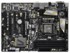
1.3 Motherboard Layout USB 2.0 T: USB0 B: USB1 1 2 21.8cm (8.6 in) 34 5 6 ATX12V1 PWR_FAN1 ...HDMI 1.4a 40 PCIE1 XFast USB AUDIO CODEC PCI Express 3.0 Z68 Extreme3 Gen3 39 PCIE2 Intel 10 SATA2_4_5 SATA2_2_3 SATA3_0_1 CMOS 38 PCIE3 Battery Super I/O 37 PCI1 SATA3 6Gb/s Z68 11 12 13 14 15 Designed in Taipei 36 35 RoHS... Power Connector (ATXPWR1) (CIR1, Gray) 9 Chassis Fan Connector (CHA_FAN2) 31 COM Port Header (COM1) 10 Intel Z68 Chipset 32 HDMI_SPDIF Header 11 SATA3 Connector (SATA3_1, Gray) (HDMI_SPDIF1, Black) 12 SATA3 Connector (SATA3_0, Gray) 33 ...
1.3 Motherboard Layout USB 2.0 T: USB0 B: USB1 1 2 21.8cm (8.6 in) 34 5 6 ATX12V1 PWR_FAN1 ...HDMI 1.4a 40 PCIE1 XFast USB AUDIO CODEC PCI Express 3.0 Z68 Extreme3 Gen3 39 PCIE2 Intel 10 SATA2_4_5 SATA2_2_3 SATA3_0_1 CMOS 38 PCIE3 Battery Super I/O 37 PCI1 SATA3 6Gb/s Z68 11 12 13 14 15 Designed in Taipei 36 35 RoHS... Power Connector (ATXPWR1) (CIR1, Gray) 9 Chassis Fan Connector (CHA_FAN2) 31 COM Port Header (COM1) 10 Intel Z68 Chipset 32 HDMI_SPDIF Header 11 SATA3 Connector (SATA3_1, Gray) (HDMI_SPDIF1, Black) 12 SATA3 Connector (SATA3_0, Gray) 33 ...

Quick Installation Guide
Page 2
Motherboard Layout USB 2.0 T: USB0 B: USB1 1 2 21.8cm (8.6 in) 3 4 5 6 ATX12V1 PWR_FAN1 CPU_FAN1 7 CPU_FAN2 PS2 Keyboard DX10.1 DDR3 ...CHA_FAN2 LAN PHY HDMI 1.4a 40 PCIE1 XFast USB AUDIO CODEC PCI Express 3.0 Z68 Extreme3 Gen3 39 PCIE2 Intel 10 SATA2_4_5 SATA2_2_3 SATA3_0_1 CMOS 38 PCIE3 Battery Super I/O 37 PCI1 SATA3 6Gb/s Z68 11 12 13 14 15 Designed in Taipei 36 35 RoHS HD_AUDIO1 1 HDMI_SPDIF1...2.0 x1 Slot (PCIE1, Black) 21 Chassis Speaker Header (SPEAKER 1, Black) 41 Chassis Fan Connector (CHA_FAN3) 2 ASRock Z68 Extreme3 Gen3 Motherboard English
Motherboard Layout USB 2.0 T: USB0 B: USB1 1 2 21.8cm (8.6 in) 3 4 5 6 ATX12V1 PWR_FAN1 CPU_FAN1 7 CPU_FAN2 PS2 Keyboard DX10.1 DDR3 ...CHA_FAN2 LAN PHY HDMI 1.4a 40 PCIE1 XFast USB AUDIO CODEC PCI Express 3.0 Z68 Extreme3 Gen3 39 PCIE2 Intel 10 SATA2_4_5 SATA2_2_3 SATA3_0_1 CMOS 38 PCIE3 Battery Super I/O 37 PCI1 SATA3 6Gb/s Z68 11 12 13 14 15 Designed in Taipei 36 35 RoHS HD_AUDIO1 1 HDMI_SPDIF1...2.0 x1 Slot (PCIE1, Black) 21 Chassis Speaker Header (SPEAKER 1, Black) 41 Chassis Fan Connector (CHA_FAN3) 2 ASRock Z68 Extreme3 Gen3 Motherboard English