
User Manual
Page 5
..." in our support CD for purchasing ASRock Z68 Extreme3 Gen3 motherboard, a reliable motherboard produced under ASRock's consistently stringent quality control. www.asrock.com/support/index.asp 1.1 Package Contents ASRock Z68 Extreme3 Gen3 Motherboard (ATX Form Factor: 12.0-in x 8.6-in Storage Configuration to set the BIOS option in , 30.5 cm x 21.8 cm) ASRock Z68 Extreme3 Gen3 Quick Installation Guide ASRock Z68 Extreme3 Gen3 Support CD 2 x Serial ATA (SATA...
..." in our support CD for purchasing ASRock Z68 Extreme3 Gen3 motherboard, a reliable motherboard produced under ASRock's consistently stringent quality control. www.asrock.com/support/index.asp 1.1 Package Contents ASRock Z68 Extreme3 Gen3 Motherboard (ATX Form Factor: 12.0-in x 8.6-in Storage Configuration to set the BIOS option in , 30.5 cm x 21.8 cm) ASRock Z68 Extreme3 Gen3 Quick Installation Guide ASRock Z68 Extreme3 Gen3 Support CD 2 x Serial ATA (SATA...

User Manual
Page 6
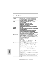
...PCI Express 3.0 with Intel® Ivy Bridge CPU, PCI Express 2.0 with Intel® Sandy Bridge CPU - resolution up to 2048x1536 @ 75Hz 6 ATX Form Factor: 12.0-in x 8.6-in LGA1155 Package - Premium Gold Capacitor design (100% Japan-made high-quality Conductive Polymer Capacitors) - Supports 2nd ... resolution up to 1920x1200 @ 60Hz - shared memory 1759MB (see CAUTION 2) - 4 x DDR3 DIMM slots - Supports DVI with max. Intel® Z68 - Supports Intel® HD Graphics Built-in Visuals: Intel® Quick Sync Video, Intel® InTruTM 3D, Intel® Clear Video HD Technology...
...PCI Express 3.0 with Intel® Ivy Bridge CPU, PCI Express 2.0 with Intel® Sandy Bridge CPU - resolution up to 2048x1536 @ 75Hz 6 ATX Form Factor: 12.0-in x 8.6-in LGA1155 Package - Premium Gold Capacitor design (100% Japan-made high-quality Conductive Polymer Capacitors) - Supports 2nd ... resolution up to 1920x1200 @ 60Hz - shared memory 1759MB (see CAUTION 2) - 4 x DDR3 DIMM slots - Supports DVI with max. Intel® Z68 - Supports Intel® HD Graphics Built-in Visuals: Intel® Quick Sync Video, Intel® InTruTM 3D, Intel® Clear Video HD Technology...

User Manual
Page 8
... 12) - CPU Frequency Stepless Control (see CAUTION 10) - Good Night LED 8 ASRock Instant Flash (see CAUTION 17) - ASRock MAGIX Multimedia Suite - ASRock Extreme Tuning Utility (AXTU) (see CAUTION 18) - ASRock U-COP (see CAUTION 9) - Hybrid Booster: - CPU/Chassis/Power FAN connector - 24 pin ATX power connector - 8 pin 12V power connector - Smart Switch BIOS Feature Support CD...
... 12) - CPU Frequency Stepless Control (see CAUTION 10) - Good Night LED 8 ASRock Instant Flash (see CAUTION 17) - ASRock MAGIX Multimedia Suite - ASRock Extreme Tuning Utility (AXTU) (see CAUTION 18) - ASRock U-COP (see CAUTION 9) - Hybrid Booster: - CPU/Chassis/Power FAN connector - 24 pin ATX power connector - 8 pin 12V power connector - Smart Switch BIOS Feature Support CD...

User Manual
Page 13
...41 9 USB 3.0 CHA_FAN3 CHA_FAN2 LAN PHY HDMI 1.4a 40 PCIE1 XFast USB AUDIO CODEC PCI Express 3.0 Z68 Extreme3 Gen3 39 PCIE2 Intel 10 SATA2_4_5 SATA2_2_3 SATA3_0_1 CMOS 38 PCIE3 Battery Super I/O 37 PCI1 SATA3 6Gb/s Z68 11 12 13 14 15 Designed in Taipei 36 35 RoHS HD_AUDIO1 1 HDMI_SPDIF1 1 IR1 1 COM1 1 ... PLED PWRBTN 1 HDLED RESET RSTBTN PWRBTN 16 17 18 19 34 33 32 31 30 29 28 27 26 25 24 23 22 21 20 1 ATX 12V Power Connector (ATX12V1) 22 64Mb SPI Flash 2 1155-Pin CPU Socket 23 Chassis Fan Connector (CHA_FAN1) 3 Power Fan Connector (PWR_FAN1) 24 Dr....
...41 9 USB 3.0 CHA_FAN3 CHA_FAN2 LAN PHY HDMI 1.4a 40 PCIE1 XFast USB AUDIO CODEC PCI Express 3.0 Z68 Extreme3 Gen3 39 PCIE2 Intel 10 SATA2_4_5 SATA2_2_3 SATA3_0_1 CMOS 38 PCIE3 Battery Super I/O 37 PCI1 SATA3 6Gb/s Z68 11 12 13 14 15 Designed in Taipei 36 35 RoHS HD_AUDIO1 1 HDMI_SPDIF1 1 IR1 1 COM1 1 ... PLED PWRBTN 1 HDLED RESET RSTBTN PWRBTN 16 17 18 19 34 33 32 31 30 29 28 27 26 25 24 23 22 21 20 1 ATX 12V Power Connector (ATX12V1) 22 64Mb SPI Flash 2 1155-Pin CPU Socket 23 Chassis Fan Connector (CHA_FAN1) 3 Power Fan Connector (PWR_FAN1) 24 Dr....

User Manual
Page 16
... note of your motherboard directly on a grounded antistatic pad or in the bag that the power is switched off or the power cord is an ATX form factor (12.0" x 8.6", 30.5 x 21.8 cm) motherboard. Do not over-tighten the screws! Also remember to you install or remove any component, place it . Whenever...
... note of your motherboard directly on a grounded antistatic pad or in the bag that the power is switched off or the power cord is an ATX form factor (12.0" x 8.6", 30.5 x 21.8 cm) motherboard. Do not over-tighten the screws! Also remember to you install or remove any component, place it . Whenever...

User Manual
Page 34
... port. Install Multi-Angle CIR Receiver to the USB 2.0 header on ASRock motherboard. Press or to the USB 2.0 header (as below procedures for ASRock motherboard with CIR header. GND IRTX IRRX ATX+5VSB Step3. Execute ASRock support CD and install CIR Driver. (It is listed at [Enabled]....option "CIR Controller" is only used for the quick installation and usage of driver list.) 34 2.10 ASRock Smart Remote Installation Guide ASRock Smart Remote is setting at the bottom of ASRock Smart Remote. Please refer to the other front USB port then try again. Step1.
... port. Install Multi-Angle CIR Receiver to the USB 2.0 header on ASRock motherboard. Press or to the USB 2.0 header (as below procedures for ASRock motherboard with CIR header. GND IRTX IRRX ATX+5VSB Step3. Execute ASRock support CD and install CIR Driver. (It is listed at [Enabled]....option "CIR Controller" is only used for the quick installation and usage of driver list.) 34 2.10 ASRock Smart Remote Installation Guide ASRock Smart Remote is setting at the bottom of ASRock Smart Remote. Please refer to the other front USB port then try again. Step1.

User Manual
Page 38
..., please install it to the front panel audio header as below: 38 Front Panel Audio Header (9-pin HD_AUDIO1) (see p.13 No. 30) 1 GND IRTX IRRX ATX+5VSB This header supports an optional wireless transmitting and receiving infrared module.
..., please install it to the front panel audio header as below: 38 Front Panel Audio Header (9-pin HD_AUDIO1) (see p.13 No. 30) 1 GND IRTX IRRX ATX+5VSB This header supports an optional wireless transmitting and receiving infrared module.

User Manual
Page 41
..., please plug your power supply along with Pin 1 and Pin 5. 8 5 Serial port Header (9-pin COM1) (see p.13 No. 31) 4-Pin ATX 12V Power Supply Installation 4 1 This COM1 header supports a serial port module. HDMI_SPDIF Header (2-pin HDMI_SPDIF1) (see p.13 No. 32) HDMI_SPDIF header, ...pin ATXPWR1) (see p.13 No. 8) 12 24 Please connect an ATX power supply to this connector. 1 13 Though this motherboard provides 8-pin ATX 12V power connector, it can still work if you adopt a traditional 4-pin ATX 12V power supply. Please connect the HDMI_SPDIF connector of HDMI VGA card to...
..., please plug your power supply along with Pin 1 and Pin 5. 8 5 Serial port Header (9-pin COM1) (see p.13 No. 31) 4-Pin ATX 12V Power Supply Installation 4 1 This COM1 header supports a serial port module. HDMI_SPDIF Header (2-pin HDMI_SPDIF1) (see p.13 No. 32) HDMI_SPDIF header, ...pin ATXPWR1) (see p.13 No. 8) 12 24 Please connect an ATX power supply to this connector. 1 13 Though this motherboard provides 8-pin ATX 12V power connector, it can still work if you adopt a traditional 4-pin ATX 12V power supply. Please connect the HDMI_SPDIF connector of HDMI VGA card to...

Quick Installation Guide
Page 2
... PLED PWRBTN 1 HDLED RESET RSTBTN PWRBTN 16 17 18 19 34 33 32 31 30 29 28 27 26 25 24 23 22 21 20 1 ATX 12V Power Connector (ATX12V1) 22 64Mb SPI Flash 2 1155-Pin CPU Socket 23 Chassis Fan Connector (CHA_FAN1) 3 Power Fan Connector (PWR_FAN1) 24 Dr. Debug 4 CPU..., Black) 20 System Panel Header (PANEL1, Black) 40 PCI Express 2.0 x1 Slot (PCIE1, Black) 21 Chassis Speaker Header (SPEAKER 1, Black) 41 Chassis Fan Connector (CHA_FAN3) 2 ASRock Z68 Extreme3 Gen3 Motherboard English
... PLED PWRBTN 1 HDLED RESET RSTBTN PWRBTN 16 17 18 19 34 33 32 31 30 29 28 27 26 25 24 23 22 21 20 1 ATX 12V Power Connector (ATX12V1) 22 64Mb SPI Flash 2 1155-Pin CPU Socket 23 Chassis Fan Connector (CHA_FAN1) 3 Power Fan Connector (PWR_FAN1) 24 Dr. Debug 4 CPU..., Black) 20 System Panel Header (PANEL1, Black) 40 PCI Express 2.0 x1 Slot (PCIE1, Black) 21 Chassis Speaker Header (SPEAKER 1, Black) 41 Chassis Fan Connector (CHA_FAN3) 2 ASRock Z68 Extreme3 Gen3 Motherboard English

Quick Installation Guide
Page 5
... to set the BIOS option in , 30.5 cm x 21.8 cm) ASRock Z68 Extreme3 Gen3 Quick Installation Guide ASRock Z68 Extreme3 Gen3 Support CD 2 x Serial ATA (SATA) Data Cables (Optional) 1 x 3.5mm Audio Cable (Optional) 1 x I/O Panel Shield 1 x ASRock SLI_Bridge_2S Card ASRock Reminds You... www.asrock.com/support/index.asp 1.1 Package Contents ASRock Z68 Extreme3 Gen3 Motherboard (ATX Form Factor: 12.0-in x 8.6-in Storage Configuration to quality...
... to set the BIOS option in , 30.5 cm x 21.8 cm) ASRock Z68 Extreme3 Gen3 Quick Installation Guide ASRock Z68 Extreme3 Gen3 Support CD 2 x Serial ATA (SATA) Data Cables (Optional) 1 x 3.5mm Audio Cable (Optional) 1 x I/O Panel Shield 1 x ASRock SLI_Bridge_2S Card ASRock Reminds You... www.asrock.com/support/index.asp 1.1 Package Contents ASRock Z68 Extreme3 Gen3 Motherboard (ATX Form Factor: 12.0-in x 8.6-in Storage Configuration to quality...
Quick Installation Guide
Page 6
... Quad CrossFireXTM and CrossFireXTM - capacity of system memory: 32GB (see CAUTION 3) - 1.2 Specifications Platform CPU Chipset Memory Expansion Slot Graphics - resolution up to 2048x1536 @ 75Hz English 6 ASRock Z68 Extreme3 Gen3 Motherboard Supports Intel® Turbo Boost 2.0 Technology - Supports DDR3 2133(OC)/1866(OC)/1600/1333/1066 non-ECC, un-buffered memory (see CAUTION 4) - resolution up...
... Quad CrossFireXTM and CrossFireXTM - capacity of system memory: 32GB (see CAUTION 3) - 1.2 Specifications Platform CPU Chipset Memory Expansion Slot Graphics - resolution up to 2048x1536 @ 75Hz English 6 ASRock Z68 Extreme3 Gen3 Motherboard Supports Intel® Turbo Boost 2.0 Technology - Supports DDR3 2133(OC)/1866(OC)/1600/1333/1066 non-ECC, un-buffered memory (see CAUTION 4) - resolution up...

Quick Installation Guide
Page 8
... Booster: - CPU Frequency Stepless Control (see CAUTION 10) - Good Night LED 8 ASRock Z68 Extreme3 Gen3 Motherboard CPU/Chassis/Power FAN connector - 24 pin ATX power connector - 8 pin 12V power connector - ACPI 1.1 Compliance Wake Up Events - OEM) Unique Feature - ASRock Instant Flash (see CAUTION 17) - ASRock XFast USB (see CAUTION 12) - Supports "Plug and Play" - CPU Core, IGPU...
... Booster: - CPU Frequency Stepless Control (see CAUTION 10) - Good Night LED 8 ASRock Z68 Extreme3 Gen3 Motherboard CPU/Chassis/Power FAN connector - 24 pin ATX power connector - 8 pin 12V power connector - ACPI 1.1 Compliance Wake Up Events - OEM) Unique Feature - ASRock Instant Flash (see CAUTION 17) - ASRock XFast USB (see CAUTION 12) - Supports "Plug and Play" - CPU Core, IGPU...

Quick Installation Guide
Page 30
... Remote is only used for the quick installation and usage of driver list.) English 3 CIR sensors in different angles 30 ASRock Z68 Extreme3 Gen3 Motherboard Find the CIR header located next to the front USB port. Step1. Step4. Make sure the option "CIR Controller" is listed at ... [Enabled]) If you cannot find this option, please shut down your system. Execute ASRock support CD and install CIR Driver. (It is setting at the bottom of ASRock Smart Remote. GND IRTX IRRX ATX+5VSB Step3. Connect the front USB cable to enter BIOS Setup Utility. Step5. Enter Windows. ...
... Remote is only used for the quick installation and usage of driver list.) English 3 CIR sensors in different angles 30 ASRock Z68 Extreme3 Gen3 Motherboard Find the CIR header located next to the front USB port. Step1. Step4. Make sure the option "CIR Controller" is listed at ... [Enabled]) If you cannot find this option, please shut down your system. Execute ASRock support CD and install CIR Driver. (It is setting at the bottom of ASRock Smart Remote. GND IRTX IRRX ATX+5VSB Step3. Connect the front USB cable to enter BIOS Setup Utility. Step5. Enter Windows. ...

Quick Installation Guide
Page 33
Please follow the instruction in our manual and chassis manual to the front panel audio header as below: 33 ASRock Z68 Extreme3 Gen3 Motherboard English Front Panel Audio Header (9-pin HD_AUDIO1) (see p.2 No. 30) 1 GND IRTX IRRX ATX+5VSB This header supports an optional wireless transmitting and receiving infrared module. Each USB 2.0 header can be used...
Please follow the instruction in our manual and chassis manual to the front panel audio header as below: 33 ASRock Z68 Extreme3 Gen3 Motherboard English Front Panel Audio Header (9-pin HD_AUDIO1) (see p.2 No. 30) 1 GND IRTX IRRX ATX+5VSB This header supports an optional wireless transmitting and receiving infrared module. Each USB 2.0 header can be used...

Quick Installation Guide
Page 36
... plug your power supply along with Pin 1 and Pin 5. 8 5 Serial port Header (9-pin COM1) (see p.2 No. 31) 4-Pin ATX 12V Power Supply Installation 4 1 This COM1 header supports a serial port module. English 36 ASRock Z68 Extreme3 Gen3 Motherboard HDMI_SPDIF Header (2-pin HDMI_SPDIF1) (see p.2 No. 32) HDMI_SPDIF header, providing SPDIF audio output to HDMI VGA card, allows...
... plug your power supply along with Pin 1 and Pin 5. 8 5 Serial port Header (9-pin COM1) (see p.2 No. 31) 4-Pin ATX 12V Power Supply Installation 4 1 This COM1 header supports a serial port module. English 36 ASRock Z68 Extreme3 Gen3 Motherboard HDMI_SPDIF Header (2-pin HDMI_SPDIF1) (see p.2 No. 32) HDMI_SPDIF header, providing SPDIF audio output to HDMI VGA card, allows...

Quick Installation Guide
Page 149
...D-Sub Auto Lip Sync), xvYCC, HBR HDMI 지원 (HDMI 7 참조 ) - DVI 및 HDMI HDCP 한국어 149 ASRock Z68 Extreme3 Gen3 Motherboard ATX 12.0" x 8.6", 30.5 x 21.8 cm 100 LGA1155 2 세대 Intel® CoreTM i7 / i5 / i3 V8 + 4 Intel®... Turbo Boost 2.0 K CPU 1 참조 ) - Intel® Z68 2 참조 ) - PCI Express 2.0 x1 슬롯 2 개 - 의 PCI 슬롯 2 &#...
...D-Sub Auto Lip Sync), xvYCC, HBR HDMI 지원 (HDMI 7 참조 ) - DVI 및 HDMI HDCP 한국어 149 ASRock Z68 Extreme3 Gen3 Motherboard ATX 12.0" x 8.6", 30.5 x 21.8 cm 100 LGA1155 2 세대 Intel® CoreTM i7 / i5 / i3 V8 + 4 Intel®... Turbo Boost 2.0 K CPU 1 참조 ) - Intel® Z68 2 참조 ) - PCI Express 2.0 x1 슬롯 2 개 - 의 PCI 슬롯 2 &#...

Quick Installation Guide
Page 158
... GND DUMMY 1 GND P+12 P-12 USB_PWR (5 핀 IR1) (2 33 (4 핀 CIR1) (2 30 IRTX +5VSB DUMMY 1 GND IRRX 1 GND IRTX IRRX ATX+5VSB (9 핀 HD_AUDIO1) ( 2 34 GND PRESENCE# MIC_RET OUT_RET 1 OUT2_L J_SENSE OUT2_R MIC2_R MIC2_L I/O 4 USB 2.0 USB 2.0 헤더가 4 USB 2.0 헤더 는 2 개의 USB 2.0 한 국 어 158 ASRock Z68 Extreme3 Gen3 Motherboard
... GND DUMMY 1 GND P+12 P-12 USB_PWR (5 핀 IR1) (2 33 (4 핀 CIR1) (2 30 IRTX +5VSB DUMMY 1 GND IRRX 1 GND IRTX IRRX ATX+5VSB (9 핀 HD_AUDIO1) ( 2 34 GND PRESENCE# MIC_RET OUT_RET 1 OUT2_L J_SENSE OUT2_R MIC2_R MIC2_L I/O 4 USB 2.0 USB 2.0 헤더가 4 USB 2.0 헤더 는 2 개의 USB 2.0 한 국 어 158 ASRock Z68 Extreme3 Gen3 Motherboard

Quick Installation Guide
Page 165
ASRock Z68 Extreme3 Gen3 CD BIOS VGA CPU サ ASRock http://www.asrock.com Web サイト い。 www.asrock.com/support/index.asp 1.1 ASRock Z68 Extreme3 Gen3 ATX 12.0-in x 8.6-in, 30.5 cm x 21.8 cm) ASRock Z68 Extreme3 Gen3 ASRock Z68 Extreme3 Gen3 CD 2 x ATA (SATA 1 x 3.5mm 1 x I/O 1 x ASRock SLI_Bridge_2S カード ASRock Windows® 7 / 7 64-bit / VistaTM / VistaTM 64-bit BIOS AHCI B I O S C D 日本語 165 ASRock Z68 Extreme3 Gen3 Motherboard
ASRock Z68 Extreme3 Gen3 CD BIOS VGA CPU サ ASRock http://www.asrock.com Web サイト い。 www.asrock.com/support/index.asp 1.1 ASRock Z68 Extreme3 Gen3 ATX 12.0-in x 8.6-in, 30.5 cm x 21.8 cm) ASRock Z68 Extreme3 Gen3 ASRock Z68 Extreme3 Gen3 CD 2 x ATA (SATA 1 x 3.5mm 1 x I/O 1 x ASRock SLI_Bridge_2S カード ASRock Windows® 7 / 7 64-bit / VistaTM / VistaTM 64-bit BIOS AHCI B I O S C D 日本語 165 ASRock Z68 Extreme3 Gen3 Motherboard

Quick Installation Guide
Page 166
... 10.1 1759MB ( 注意 5 3 つの VGA D-Sub、DVI-D、HDMI ( 注意 6 1920x1200 @ 60Hz HDMI 1.4a 1920x1200 @ 60Hz DVI ASRock Z68 Extreme3 Gen3 Motherboard 日本語 1.2 仕様 CPU 166 - ATX 12.0-in x 8.6-in, 30.5 cm x 21.8 cm 100 - 第 2 世代の Intel® CoreTM i7 / i5 / i3 in LGA1155 - 高...
... 10.1 1759MB ( 注意 5 3 つの VGA D-Sub、DVI-D、HDMI ( 注意 6 1920x1200 @ 60Hz HDMI 1.4a 1920x1200 @ 60Hz DVI ASRock Z68 Extreme3 Gen3 Motherboard 日本語 1.2 仕様 CPU 166 - ATX 12.0-in x 8.6-in, 30.5 cm x 21.8 cm 100 - 第 2 世代の Intel® CoreTM i7 / i5 / i3 in LGA1155 - 高...

Quick Installation Guide
Page 175
HAD い。 ASRock Z68 Extreme3 Gen3 Motherboard 175 USB 2.0 ヘッダ (9 ピン USB6_7 29 を参照 (9 ピン USB8_9 28 を参照 (9 ピ... P+12 P-12 USB_PWR 5 ピン IR1 33 を参照 IRTX +5VSB DUMMY 1 GND IRRX 4 ピン CIR1 30 を参照 1 GND IRTX IRRX ATX+5VSB I/O 4 つの USB 2.0 4 つの USB 2.0 USB 2.0 2 つの USB 2.0 日本語 9 ピン HD_AUDIO1 34 を参&#...
HAD い。 ASRock Z68 Extreme3 Gen3 Motherboard 175 USB 2.0 ヘッダ (9 ピン USB6_7 29 を参照 (9 ピン USB8_9 28 を参照 (9 ピ... P+12 P-12 USB_PWR 5 ピン IR1 33 を参照 IRTX +5VSB DUMMY 1 GND IRRX 4 ピン CIR1 30 を参照 1 GND IRTX IRRX ATX+5VSB I/O 4 つの USB 2.0 4 つの USB 2.0 USB 2.0 2 つの USB 2.0 日本語 9 ピン HD_AUDIO1 34 を参&#...