User Manual
Page 6
... 1.1 Package Contents 1 1.2 Specifications 2 1.3 Motherboard Layout 9 1.4 I/O Panel 11 1.5 802.11ax Wi-Fi 6E Module and ASRock WiFi 2.4/5/6 GHz Antennas 13 1.6 Graphics Card Holder 15 1.7 3010 Cooling Fan with Bracket 16 1.8 4010 Cooling Fan Bracket 17 1.9 Wireless Dongle USB Bracket 18 Chapter 2 Installation 19 2.1 Installing the CPU 20 2.2 Installing the CPU Fan and Heatsink 23 2.3 Installing Memory Modules (DIMM) 24 2.4 Expansion Slots (PCI Express Slots) 26 2.5 Jumpers Setup 28 2.6 Onboard Headers and Connectors 29 2.7 Smart Switches 35 2.8 Dr. Debug 37...
... 1.1 Package Contents 1 1.2 Specifications 2 1.3 Motherboard Layout 9 1.4 I/O Panel 11 1.5 802.11ax Wi-Fi 6E Module and ASRock WiFi 2.4/5/6 GHz Antennas 13 1.6 Graphics Card Holder 15 1.7 3010 Cooling Fan with Bracket 16 1.8 4010 Cooling Fan Bracket 17 1.9 Wireless Dongle USB Bracket 18 Chapter 2 Installation 19 2.1 Installing the CPU 20 2.2 Installing the CPU Fan and Heatsink 23 2.3 Installing Memory Modules (DIMM) 24 2.4 Expansion Slots (PCI Express Slots) 26 2.5 Jumpers Setup 28 2.6 Onboard Headers and Connectors 29 2.7 Smart Switches 35 2.8 Dr. Debug 37...

User Manual
Page 9
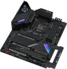
... contains the operation guide of the BIOS setup. You may find the latest VGA cards and CPU support list on ASRock's website without notice. Chapter 4 contains the configuration guide of the software and utilities. ASRock website http://www.asrock.com. 1.1 Package Contents • ASRock Z590 Taichi Motherboard (ATX Form Factor) • ASRock Z590 Taichi Quick Installation Guide • ASRock Z590 Taichi Support CD • 4 x Serial ATA (SATA) Data Cables (Optional) • 1 x Graphics Card Holder (Optional) • 1 x Wireless Dongle USB Bracket (Optional) • 1 x 3010...
... contains the operation guide of the BIOS setup. You may find the latest VGA cards and CPU support list on ASRock's website without notice. Chapter 4 contains the configuration guide of the software and utilities. ASRock website http://www.asrock.com. 1.1 Package Contents • ASRock Z590 Taichi Motherboard (ATX Form Factor) • ASRock Z590 Taichi Quick Installation Guide • ASRock Z590 Taichi Support CD • 4 x Serial ATA (SATA) Data Cables (Optional) • 1 x Graphics Card Holder (Optional) • 1 x Wireless Dongle USB Bracket (Optional) • 1 x 3010...
User Manual
Page 15
... Panel Type C USB 3.2 Gen2x2 Header (20 Gb/s) (Supports ESD Protection) • 1 x Clear CMOS Button • 1 x Dr. Debug with LED • 1 x Power Button with LED • 1 x Reset Button with LED BIOS Feature • AMI UEFI Legal BIOS with multilingual GUI support • ACPI 6.0 Compliant wake up events • SMBIOS 2.7 Support • CPU Core/Cache, CPU GT, DRAM(VCCM, VPPM, VTT), VCCSFR, VCCPLL, VCCSTG, VCCSTG_OUT, PCH Voltage, VCCIO_0, VCCIO_1_2, VCCST, VCCSA, CPU Internal PLL, GT PLL, Ring PLL, System Agent PLL, Memory Controller...
... Panel Type C USB 3.2 Gen2x2 Header (20 Gb/s) (Supports ESD Protection) • 1 x Clear CMOS Button • 1 x Dr. Debug with LED • 1 x Power Button with LED • 1 x Reset Button with LED BIOS Feature • AMI UEFI Legal BIOS with multilingual GUI support • ACPI 6.0 Compliant wake up events • SMBIOS 2.7 Support • CPU Core/Cache, CPU GT, DRAM(VCCM, VPPM, VTT), VCCSFR, VCCPLL, VCCSTG, VCCSTG_OUT, PCH Voltage, VCCIO_0, VCCIO_1_2, VCCST, VCCSA, CPU Internal PLL, GT PLL, Ring PLL, System Agent PLL, Memory Controller...
User Manual
Page 18
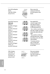
... Chassis/Water Pump Fan Connector (CHA_FAN4/WP) 19 Power LED and Speaker Header (SPK_PLED1) 20 System Panel Header (PANEL1) 21 Power Button (PWRBTN1) 22 Clear CMOS Button (CLRCBTN1) 23 Reset Button (RSTBTN1) 24 USB 2.0 Header (USB_3_4) 25 USB 2.0 Header (USB_1_2) 26 SPI TPM Header (SPI_TPM_J1) 27 Clear CMOS Jumper (CLRMOS1) 28 RGB LED Header (RGB_LED1) 29 Chassis/Water Pump Fan Connector (CHA_FAN6/WP) 30 Chassis/Water Pump Fan Connector (CHA_FAN5/WP) 31 Addressable LED Header (ADDR_LED1) 32 Front Panel Audio Header (HD_AUDIO1) 33 CPU Fan Connector (CPU_FAN1) 34 CPU/Water Pump Fan Connector...
... Chassis/Water Pump Fan Connector (CHA_FAN4/WP) 19 Power LED and Speaker Header (SPK_PLED1) 20 System Panel Header (PANEL1) 21 Power Button (PWRBTN1) 22 Clear CMOS Button (CLRCBTN1) 23 Reset Button (RSTBTN1) 24 USB 2.0 Header (USB_3_4) 25 USB 2.0 Header (USB_1_2) 26 SPI TPM Header (SPI_TPM_J1) 27 Clear CMOS Jumper (CLRMOS1) 28 RGB LED Header (RGB_LED1) 29 Chassis/Water Pump Fan Connector (CHA_FAN6/WP) 30 Chassis/Water Pump Fan Connector (CHA_FAN5/WP) 31 Addressable LED Header (ADDR_LED1) 32 Front Panel Audio Header (HD_AUDIO1) 33 CPU Fan Connector (CPU_FAN1) 34 CPU/Water Pump Fan Connector...
User Manual
Page 38
If either one of them is in use Intel® Z590 SATA ports (SATA3_0) for internal storage devices with up to this motherboard. Each USB 2.0 header can support two ports. Power LED and Speaker Header (7-pin SPK_PLED1) (see p.9, No. 19) Serial ATA3 Connectors Right Angle: (SATA3_0: see p.9, No. 13)(Upper) (SATA3_1: see p.9, No. 13)(Lower) (SATA3_2: see p.9, No. 14)(Upper) (SATA3_3: see p.9, No. 14)(Lower) (SATA3_4: see p.9, No. ...
If either one of them is in use Intel® Z590 SATA ports (SATA3_0) for internal storage devices with up to this motherboard. Each USB 2.0 header can support two ports. Power LED and Speaker Header (7-pin SPK_PLED1) (see p.9, No. 19) Serial ATA3 Connectors Right Angle: (SATA3_0: see p.9, No. 13)(Upper) (SATA3_1: see p.9, No. 13)(Lower) (SATA3_2: see p.9, No. 14)(Upper) (SATA3_3: see p.9, No. 14)(Lower) (SATA3_4: see p.9, No. ...
User Manual
Page 39
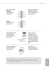
Z590 Taichi USB 3.2 Gen1 Headers Right Angle: (19-pin USB3_7_8) (see p.9, No. 11) USB Type-C Cable There is one Front Panel Type C USB 3.2 Gen2x2 Header on this motherboard. Vbus There are two headers on the chassis must support HDA to install your system. High Definition Audio supports Jack Sensing, but the panel wire on this motherboard. Vbus IntA_PA_D+ IntA_PA_DGND IntA_PA_SSTX+ IntA_PA_SSTXGND IntA_PA_SSRX+ IntA_PA_SSRX- Vertical: (19-pin USB3_9_10) (see p.9, No. 8) Vbus IntA_PA_SSRXIntA_PA_SSRX+ GND IntA_PA_SSTXIntA_PA_SSTX+ GND IntA_PA_DIntA_PA_D...
Z590 Taichi USB 3.2 Gen1 Headers Right Angle: (19-pin USB3_7_8) (see p.9, No. 11) USB Type-C Cable There is one Front Panel Type C USB 3.2 Gen2x2 Header on this motherboard. Vbus There are two headers on the chassis must support HDA to install your system. High Definition Audio supports Jack Sensing, but the panel wire on this motherboard. Vbus IntA_PA_D+ IntA_PA_DGND IntA_PA_SSTX+ IntA_PA_SSTXGND IntA_PA_SSRX+ IntA_PA_SSRX- Vertical: (19-pin USB3_9_10) (see p.9, No. 8) Vbus IntA_PA_SSRXIntA_PA_SSRX+ GND IntA_PA_SSTXIntA_PA_SSTX+ GND IntA_PA_DIntA_PA_D...
User Manual
Page 41
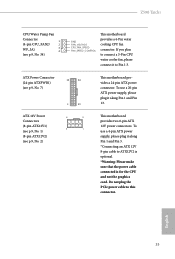
Z590 Taichi CPU/Water Pump Fan Connector 1 (4-pin CPU_FAN2/ 2 WP_3A) 3 4 (see p.9, No. 2) 1 13 8 5 4 1 This motherboard provides a 24-pin ATX power connector. To use a 4-pin ATX power supply, please plug it along Pin 1 and Pin 5. *Connecting an ATX 12V 8-pin cable to ATX12V2 is optional. *Warning: Please make sure that the power cable connected is for the CPU and not the graphics card. To use a 20-pin ATX power supply, please plug it along Pin 1 and Pin 13. Do not plug the PCIe power cable to Pin 1-3. English 33 This motherboard provides two 8-pin ATX 12V power...
Z590 Taichi CPU/Water Pump Fan Connector 1 (4-pin CPU_FAN2/ 2 WP_3A) 3 4 (see p.9, No. 2) 1 13 8 5 4 1 This motherboard provides a 24-pin ATX power connector. To use a 4-pin ATX power supply, please plug it along Pin 1 and Pin 5. *Connecting an ATX 12V 8-pin cable to ATX12V2 is optional. *Warning: Please make sure that the power cable connected is for the CPU and not the graphics card. To use a 20-pin ATX power supply, please plug it along Pin 1 and Pin 13. Do not plug the PCIe power cable to Pin 1-3. English 33 This motherboard provides two 8-pin ATX 12V power...
User Manual
Page 44
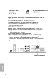
... below. 1. Download the latest BIOS file from the zip file. 4. Plug the 24 pin power connector to blink. 8. Then the LED starts to the motherboard. Please make sure the file system of X: USB flash drive. 5. Please make sure that the BIOS Flashback is no need to update BIOS without CPU. Then plug your USB flash drive must be FAT32. 3. Wait until the LED stops blinking, indicating that BIOS flashing has been completed. *If the LED light turns solid green...
... below. 1. Download the latest BIOS file from the zip file. 4. Plug the 24 pin power connector to blink. 8. Then the LED starts to the motherboard. Please make sure the file system of X: USB flash drive. 5. Please make sure that the BIOS Flashback is no need to update BIOS without CPU. Then plug your USB flash drive must be FAT32. 3. Wait until the LED stops blinking, indicating that BIOS flashing has been completed. *If the LED light turns solid green...
User Manual
Page 51
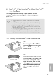
... the slots. Z590 Taichi 2.9 CrossFireXTM , 3-Way CrossFireXTM and Quad CrossFireXTM Operation Guide This motherboard supports CrossFireXTM, 3-way CrossFireXTM and Quad CrossFireXTM that allows you to install up to enable CrossFireXTM. Different CrossFireXTM cards may require different methods to three identical PCI Express x16 graphics cards. 1. Please refer to AMD graphics card manuals for detailed installation guide. 2.9.1 Installing Two CrossFireXTM-Ready Graphics Cards Step 1 Insert one graphics card into PCIE1 slot and the other graphics card to your graphics card...
... the slots. Z590 Taichi 2.9 CrossFireXTM , 3-Way CrossFireXTM and Quad CrossFireXTM Operation Guide This motherboard supports CrossFireXTM, 3-way CrossFireXTM and Quad CrossFireXTM that allows you to install up to enable CrossFireXTM. Different CrossFireXTM cards may require different methods to three identical PCI Express x16 graphics cards. 1. Please refer to AMD graphics card manuals for detailed installation guide. 2.9.1 Installing Two CrossFireXTM-Ready Graphics Cards Step 1 Insert one graphics card into PCIE1 slot and the other graphics card to your graphics card...
User Manual
Page 54
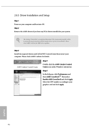
... an optional download. Please check AMD's website for AMD driver updates. Select the GPU number according to your computer. Then select Enable AMD CrossFireX and click Apply. Please check AMD's website for details. Step 3 Install the required drivers and CATALYST Control Center then restart your graphics card and click Apply. English 46 We recommend using this utility to installation. AMD Catalyst Control Center Step 4 Double-click the AMD Catalyst Control Center...
... an optional download. Please check AMD's website for AMD driver updates. Select the GPU number according to your computer. Then select Enable AMD CrossFireX and click Apply. Please check AMD's website for details. Step 3 Install the required drivers and CATALYST Control Center then restart your graphics card and click Apply. English 46 We recommend using this utility to installation. AMD Catalyst Control Center Step 4 Double-click the AMD Catalyst Control Center...

User Manual
Page 69
..., locate and double click on the support CD driver page. Therefore, the drivers you install can work properly. Drivers Menu The drivers compatible to your system will be auto-detected and listed on the file "ASRSETUP.EXE" in your CD-ROM drive. Running The Support CD To begin using the support CD, insert the CD into your computer. Utilities Menu The Utilities Menu shows the application software that enhance the motherboard's features. Z590 Taichi Chapter 3 Software and Utilities...
..., locate and double click on the support CD driver page. Therefore, the drivers you install can work properly. Drivers Menu The drivers compatible to your system will be auto-detected and listed on the file "ASRSETUP.EXE" in your CD-ROM drive. Running The Support CD To begin using the support CD, insert the CD into your computer. Utilities Menu The Utilities Menu shows the application software that enhance the motherboard's features. Z590 Taichi Chapter 3 Software and Utilities...
User Manual
Page 104
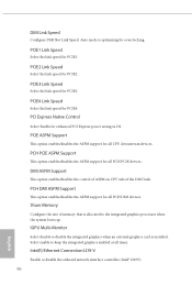
... support for all CPU downstream devices. DMI ASPM Support This option enables/disables the control of ASPM on CPU side of memory that is allocated to disable the integrated graphics when an external graphics card is optimizing for PCIE1. PCH PCIE ASPM Support This option enables/disables the ASPM support for all PCH PCIE devices. IGPU Multi-Monitor Select disable to the integrated graphics processor when the system boots up. Auto mode is installed. PCIE1 Link Speed Select the link speed for overclocking...
... support for all CPU downstream devices. DMI ASPM Support This option enables/disables the control of ASPM on CPU side of memory that is allocated to disable the integrated graphics when an external graphics card is optimizing for PCIE1. PCH PCIE ASPM Support This option enables/disables the ASPM support for all PCH PCIE devices. IGPU Multi-Monitor Select disable to the integrated graphics processor when the system boots up. Auto mode is installed. PCIE1 Link Speed Select the link speed for overclocking...
User Manual
Page 105
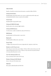
... start to boot up when the power recovers. Bluetooth Enable/disable the Bluetooth connectivity. If [Power On] is shut down. RGB LED This option enables/disables the RGB LED. 97 English Deep Sleep Configure deep sleep mode for the onboard digital outputs. Restore on Onboard LED in the ACPI S5 state. Turn On Onboard LED in S5 Turn on AC/Power Loss Select the power state after a power failure. Restore Onboard LED Default Restore Onboard LED default value. If [Power Off] is installed. Front Panel Enable/disable front panel HD audio. Z590 Taichi...
... start to boot up when the power recovers. Bluetooth Enable/disable the Bluetooth connectivity. If [Power On] is shut down. RGB LED This option enables/disables the RGB LED. 97 English Deep Sleep Configure deep sleep mode for the onboard digital outputs. Restore on Onboard LED in the ACPI S5 state. Turn On Onboard LED in S5 Turn on AC/Power Loss Select the power state after a power failure. Restore Onboard LED Default Restore Onboard LED default value. If [Power Off] is installed. Front Panel Enable/disable front panel HD audio. Z590 Taichi...
User Manual
Page 107
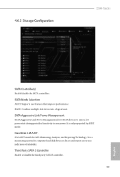
...99 English S.M.A.R.T stands for computer hard disk drives to detect and report on various indicators of inactivity to enter a low power state during periods of reliability. Hard Disk S.M.A.R.T. SATA Aggressive Link Power Management SATA Aggressive Link Power Management allows SATA devices to save power. It is only supported by AHCI mode. It is a monitoring system for Self-Monitoring, Analysis, and Reporting Technology. 4.6.3 Storage Configuration Z590 Taichi SATA Controller(s) Enable/disable the SATA controllers. RAID: Combine multiple disk drives into a logical unit.
...99 English S.M.A.R.T stands for computer hard disk drives to detect and report on various indicators of inactivity to enter a low power state during periods of reliability. Hard Disk S.M.A.R.T. SATA Aggressive Link Power Management SATA Aggressive Link Power Management allows SATA devices to save power. It is only supported by AHCI mode. It is a monitoring system for Self-Monitoring, Analysis, and Reporting Technology. 4.6.3 Storage Configuration Z590 Taichi SATA Controller(s) Enable/disable the SATA controllers. RAID: Combine multiple disk drives into a logical unit.
User Manual
Page 110
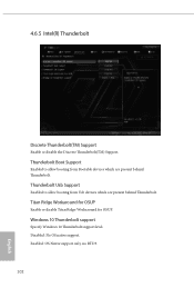
4.6.5 Intel(R) Thunderbolt Discrete Thunderbolt(TM) Support Enable or disable the Discrete Thunderbolt(TM) Support. Thunderbolt Boot Support Enabled to allow booting from Usb devices which are present behind Thunderbolt. Thunderbolt Usb Support Enabled to allow booting from Bootable devices which are present behind Thunderbolt. Enabled: OS Native support only. Windows 10 Thunderbolt support Specify Windows 10 Thunderbolt support level. Titan Ridge Workaround for OSUP Enable or disable Titan Ridge Workaround for OSUP. no RTD3...
4.6.5 Intel(R) Thunderbolt Discrete Thunderbolt(TM) Support Enable or disable the Discrete Thunderbolt(TM) Support. Thunderbolt Boot Support Enabled to allow booting from Usb devices which are present behind Thunderbolt. Thunderbolt Usb Support Enabled to allow booting from Bootable devices which are present behind Thunderbolt. Enabled: OS Native support only. Windows 10 Thunderbolt support Specify Windows 10 Thunderbolt support level. Titan Ridge Workaround for OSUP Enable or disable Titan Ridge Workaround for OSUP. no RTD3...
User Manual
Page 115
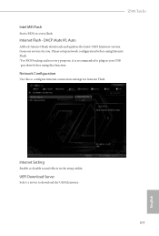
Network Configuration Use this function. Z590 Taichi Intel MEI Flash Starts BIOS recovery flash. Please setup network configuration before using this to plug in the setup utility. Internet Setting Enable or disable sound effects in your USB pen drive before using Internet Flash. *For BIOS backup and recovery purpose, it is recommended to configure internet connection settings for you. Internet Flash - DHCP (Auto IP), Auto ASRock Internet Flash downloads and updates the latest UEFI firmware version from our servers for Internet Flash. UEFI Download Server Select a server ...
Network Configuration Use this function. Z590 Taichi Intel MEI Flash Starts BIOS recovery flash. Please setup network configuration before using this to plug in the setup utility. Internet Setting Enable or disable sound effects in your USB pen drive before using Internet Flash. *For BIOS backup and recovery purpose, it is recommended to configure internet connection settings for you. Internet Flash - DHCP (Auto IP), Auto ASRock Internet Flash downloads and updates the latest UEFI firmware version from our servers for Internet Flash. UEFI Download Server Select a server ...
User Manual
Page 120
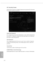
Supervisor Password Set or change the settings in the UEFI Setup Utility. Leave it blank and press enter to remove the password. Disable this item to change the password for Secure Boot. Intel(R) Platform Trust Technology Enable/disable Intel PTT in the UEFI Setup Utility. Users are unable to enable or disable support for the administrator account. Only the administrator has authority to use discrete TPM Module. 112 English Secure Boot Use this option to change the password for the system...
Supervisor Password Set or change the settings in the UEFI Setup Utility. Leave it blank and press enter to remove the password. Disable this item to change the password for Secure Boot. Intel(R) Platform Trust Technology Enable/disable Intel PTT in the UEFI Setup Utility. Users are unable to enable or disable support for the administrator account. Only the administrator has authority to use discrete TPM Module. 112 English Secure Boot Use this option to change the password for the system...
RAID Installation Guide
Page 7
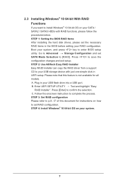
... HDDs with just one simple click in the BIOS before setting your RAID configuration. Please note that this document for all models A. Go to Advanced Storage Configuration and set RAID configuration. STEP 1: Setting the BIOS RAID Items After installing the hard disk drives, please set the necessary RAID items in UEFI setup. Boot your system. 7 STEP 4: Install Windows® 10 64-bit OS on your system, and press key to save the configuration changes and exit setup. Plug in your USB flash drive into a USB port B. Enter UEFI SETUP UTILITY...
... HDDs with just one simple click in the BIOS before setting your RAID configuration. Please note that this document for all models A. Go to Advanced Storage Configuration and set RAID configuration. STEP 1: Setting the BIOS RAID Items After installing the hard disk drives, please set the necessary RAID items in UEFI setup. Boot your system. 7 STEP 4: Install Windows® 10 64-bit OS on your system, and press key to save the configuration changes and exit setup. Plug in your USB flash drive into a USB port B. Enter UEFI SETUP UTILITY...
RAID Installation Guide
Page 23
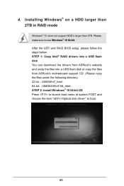
... boot. 23 STEP 2: Install Windows® 10 64-bit OS Press to launch boot menu at system POST and choose the item "UEFI:" to use Windows® 10 64-bit. Installing Windows® on a HDD larger than 2TB in RAID mode Windows® 10 does not support HDD's larger than 2TB. STEP 1: Copy Intel® RAID drivers into a USB flash disk You can download the drivers from ASRock's website and unzip the files into a USB flash disk or copy the files from ASRock's motherboard support...
... boot. 23 STEP 2: Install Windows® 10 64-bit OS Press to launch boot menu at system POST and choose the item "UEFI:" to use Windows® 10 64-bit. Installing Windows® on a HDD larger than 2TB in RAID mode Windows® 10 does not support HDD's larger than 2TB. STEP 1: Copy Intel® RAID drivers into a USB flash disk You can download the drivers from ASRock's website and unzip the files into a USB flash disk or copy the files from ASRock's motherboard support...
Intel Rapid Storage Guide
Page 13
... support disk into Drive A:, insert ;a floppy disk containing the following steps to confirm your controller from the list of Windows setup (during operating system setup: 1. Press Enter to confirm volume creation. 10. Press Y to install the Intel Rapid Storage Technology driver during text-mode phase). Install the RAID Driver Using the F6 Installation Method Perform the following files: IAAHCI.INF, IAAHCI.CAT, IASTOR.INF, IASTOR.CAT, IASTOR.SYS, and TXTSETUP.OEM. Use the Floppy Configuration Utility...
... support disk into Drive A:, insert ;a floppy disk containing the following steps to confirm your controller from the list of Windows setup (during operating system setup: 1. Press Enter to confirm volume creation. 10. Press Y to install the Intel Rapid Storage Technology driver during text-mode phase). Install the RAID Driver Using the F6 Installation Method Perform the following files: IAAHCI.INF, IAAHCI.CAT, IASTOR.INF, IASTOR.CAT, IASTOR.SYS, and TXTSETUP.OEM. Use the Floppy Configuration Utility...


