
User Manual
Page 5
... Chapter 1 Introduction 1 1.1 Package Contents 1 1.2 Specifications 2 1.3 Motherboard Layout 8 1.4 I/O Panel 10 1.5 Graphics Card Holder 12 Chapter 2 Installation 13 2.1 Installing the CPU 14 2.2 Installing the CPU Fan and Heatsink 17 2.3 Installing Memory Modules (DIMM) 18 2.4 Expansion Slots (PCI Express Slots) 20 2.5 Jumpers Setup 22 2.6 Onboard Headers and Connectors 23 2.7 Smart Switches 29 2.8 Post Status Checker 30 2.9 CrossFireXTM and Quad CrossFireXTM Operation Guide 31 2.9.1 Installing Two CrossFireXTM-Ready Graphics Cards 31 2.10 M.2 WiFi/BT Module...
... Chapter 1 Introduction 1 1.1 Package Contents 1 1.2 Specifications 2 1.3 Motherboard Layout 8 1.4 I/O Panel 10 1.5 Graphics Card Holder 12 Chapter 2 Installation 13 2.1 Installing the CPU 14 2.2 Installing the CPU Fan and Heatsink 17 2.3 Installing Memory Modules (DIMM) 18 2.4 Expansion Slots (PCI Express Slots) 20 2.5 Jumpers Setup 22 2.6 Onboard Headers and Connectors 23 2.7 Smart Switches 29 2.8 Post Status Checker 30 2.9 CrossFireXTM and Quad CrossFireXTM Operation Guide 31 2.9.1 Installing Two CrossFireXTM-Ready Graphics Cards 31 2.10 M.2 WiFi/BT Module...
User Manual
Page 8
...; ASRock Z590 Extreme Support CD • 4 x Serial ATA (SATA) Data Cables (Optional) • 4 x Screws for M.2 Sockets (Optional) • 2 x Standoffs for purchasing ASRock Z590 Extreme motherboard, a reliable motherboard produced under ASRock's consistently stringent quality control. If you require technical support related to quality and endurance. Because the motherboard specifications and the BIOS software might be updated, the content of the motherboard and step-by-step installation guides. Chapter 3 contains the operation guide of the BIOS setup. In this motherboard...
...; ASRock Z590 Extreme Support CD • 4 x Serial ATA (SATA) Data Cables (Optional) • 4 x Screws for M.2 Sockets (Optional) • 2 x Standoffs for purchasing ASRock Z590 Extreme motherboard, a reliable motherboard produced under ASRock's consistently stringent quality control. If you require technical support related to quality and endurance. Because the motherboard specifications and the BIOS software might be updated, the content of the motherboard and step-by-step installation guides. Chapter 3 contains the operation guide of the BIOS setup. In this motherboard...
User Manual
Page 12
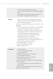
English 5 Z590 Extreme • 2 x USB 2.0 Ports (Supports ESD Protection) • 2 x RJ-45 LAN Ports with LED (ACT/LINK LED and SPEED LED) • HD Audio Jacks: Rear Speaker / Central / Bass / Line in / Front Speaker / Microphone (Gold Audio Jacks) Storage • 6 x SATA3 6.0 Gb/s Connectors, support RAID (RAID 0, RAID 1, RAID 5, RAID 10, Intel Rapid Storage Technology 18), NCQ, AHCI and Hot Plug* * If M2_2 is occupied by a SATA-type M.2 device, SATA3_1 will be disabled. * If M2_3 is occupied, SATA3_4 and SATA3_5 will be disabled. •...
English 5 Z590 Extreme • 2 x USB 2.0 Ports (Supports ESD Protection) • 2 x RJ-45 LAN Ports with LED (ACT/LINK LED and SPEED LED) • HD Audio Jacks: Rear Speaker / Central / Bass / Line in / Front Speaker / Microphone (Gold Audio Jacks) Storage • 6 x SATA3 6.0 Gb/s Connectors, support RAID (RAID 0, RAID 1, RAID 5, RAID 10, Intel Rapid Storage Technology 18), NCQ, AHCI and Hot Plug* * If M2_2 is occupied by a SATA-type M.2 device, SATA3_1 will be disabled. * If M2_3 is occupied, SATA3_4 and SATA3_5 will be disabled. •...

User Manual
Page 13
... Front Panel Type C USB 3.2 Gen2x2 Header (20 Gb/s) (Supports ESD Protection) • 1 x Power Button with LED • 1 x Reset Button with LED BIOS Feature • AMI UEFI Legal BIOS with multilingual GUI support • ACPI 6.0 Compliant wake up events • SMBIOS 2.7 Support • CPU Core/Cache, CPU GT, VCCSA, DRAM, VCCIO, VCCIO 1 2, VPPM, VCCIN AUX, VCCST Voltage Multiadjustment Hardware Monitor • Fan Tachometer: CPU, CPU/Water Pump, Chassis/Water Pump Fans • Quiet Fan (Auto adjust chassis fan speed by CPU temperature): CPU, CPU/Water Pump, Chassis/Water Pump Fans...
... Front Panel Type C USB 3.2 Gen2x2 Header (20 Gb/s) (Supports ESD Protection) • 1 x Power Button with LED • 1 x Reset Button with LED BIOS Feature • AMI UEFI Legal BIOS with multilingual GUI support • ACPI 6.0 Compliant wake up events • SMBIOS 2.7 Support • CPU Core/Cache, CPU GT, VCCSA, DRAM, VCCIO, VCCIO 1 2, VPPM, VCCIN AUX, VCCST Voltage Multiadjustment Hardware Monitor • Fan Tachometer: CPU, CPU/Water Pump, Chassis/Water Pump Fans • Quiet Fan (Auto adjust chassis fan speed by CPU temperature): CPU, CPU/Water Pump, Chassis/Water Pump Fans...

User Manual
Page 16
...) 9 Reset Button (RSTBTN1) 10 ATX Power Connector (ATXPWR1) 11 Front Panel Type C USB 3.2 Gen2x2 Header (USB31_TC_2) 12 USB 3.2 Gen1 Header (USB3_5_6) 13 CPU Fan Connector (CPU_FAN1) 14 SATA3 Connector (SATA3_2)(Upper), (SATA3_3)(Lower) 15 SATA3 Connector (SATA3_4)(Upper), (SATA3_5)(Lower) 16 POST Status Checker (PSC) 17 Power LED and Speaker Header (SPK_PLED1) 18 SPI TPM Header (SPI_TPM_J1) 19 Chassis/Water Pump Fan Connector (CHA_FAN3/WP) 20 SATA3 Connector (SATA3_0) 21 SATA3 Connector (SATA3_1) 22 System Panel Header (PANEL1) 23 Clear CMOS Jumper...
...) 9 Reset Button (RSTBTN1) 10 ATX Power Connector (ATXPWR1) 11 Front Panel Type C USB 3.2 Gen2x2 Header (USB31_TC_2) 12 USB 3.2 Gen1 Header (USB3_5_6) 13 CPU Fan Connector (CPU_FAN1) 14 SATA3 Connector (SATA3_2)(Upper), (SATA3_3)(Lower) 15 SATA3 Connector (SATA3_4)(Upper), (SATA3_5)(Lower) 16 POST Status Checker (PSC) 17 Power LED and Speaker Header (SPK_PLED1) 18 SPI TPM Header (SPI_TPM_J1) 19 Chassis/Water Pump Fan Connector (CHA_FAN3/WP) 20 SATA3 Connector (SATA3_0) 21 SATA3 Connector (SATA3_1) 22 System Panel Header (PANEL1) 23 Clear CMOS Jumper...

User Manual
Page 34
... power cable connected is for the CPU and not the graphics card. English 27 SPI TPM Header (13-pin SPI_TPM_J1) (see p.8, No. 18) SPI_DQ3 +3.3V Dummy CLK SPI_MOSI RST# TPM_PIRQ 1 SPI_TPM_CS# GND RSMRST# SPI_MISO SPI_CS0 SPI_DQ2 This connector supports SPI Trusted Platform Module (TPM) system, which can securely store keys, digital certificates, passwords, and data. To 4 1 use a 4-pin ATX power supply, please plug it along Pin 1 and Pin 5. *Connecting an ATX 12V 8-pin cable...
... power cable connected is for the CPU and not the graphics card. English 27 SPI TPM Header (13-pin SPI_TPM_J1) (see p.8, No. 18) SPI_DQ3 +3.3V Dummy CLK SPI_MOSI RST# TPM_PIRQ 1 SPI_TPM_CS# GND RSMRST# SPI_MISO SPI_CS0 SPI_DQ2 This connector supports SPI Trusted Platform Module (TPM) system, which can securely store keys, digital certificates, passwords, and data. To 4 1 use a 4-pin ATX power supply, please plug it along Pin 1 and Pin 5. *Connecting an ATX 12V 8-pin cable...

User Manual
Page 38
... CrossFireXTM mode. 5. If you to install up to use a AMD certified PSU. Make sure that are properly seated on the top of the graphics cards. (The CrossFire Bridge is recommended to three identical PCI Express x16 graphics cards. 1. You should only use identical CrossFireXTM-ready graphics cards that the cards are AMD certified. 2. Z590 Extreme 2.9 CrossFireXTM and Quad CrossFireXTM Operation Guide This motherboard supports CrossFireXTM and Quad CrossFireXTM that your power supply...
... CrossFireXTM mode. 5. If you to install up to use a AMD certified PSU. Make sure that are properly seated on the top of the graphics cards. (The CrossFire Bridge is recommended to three identical PCI Express x16 graphics cards. 1. You should only use identical CrossFireXTM-ready graphics cards that the cards are AMD certified. 2. Z590 Extreme 2.9 CrossFireXTM and Quad CrossFireXTM Operation Guide This motherboard supports CrossFireXTM and Quad CrossFireXTM that your power supply...
User Manual
Page 40
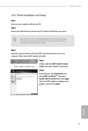
... an optional download. Step 3 Install the required drivers and CATALYST Control Center then restart your graphics card and click Apply. Please check AMD's website for AMD driver updates. Step 5 In the left pane, click Performance and then AMD CrossFireXTM. Select the GPU number according to uninstall any VGA drivers installed in the Windows® system tray. English 33 We recommend using this utility to your computer. Z590 Extreme 2.9.3 Driver Installation and Setup Step 1 Power...
... an optional download. Step 3 Install the required drivers and CATALYST Control Center then restart your graphics card and click Apply. Please check AMD's website for AMD driver updates. Step 5 In the left pane, click Performance and then AMD CrossFireXTM. Select the GPU number according to uninstall any VGA drivers installed in the Windows® system tray. English 33 We recommend using this utility to your computer. Z590 Extreme 2.9.3 Driver Installation and Setup Step 1 Power...
User Manual
Page 56
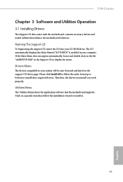
..., locate and double click on the support CD driver page. Utilities Menu The Utilities Menu shows the application software that enhance the motherboard's features. Drivers Menu The drivers compatible to display the menu. The CD automatically displays the Main Menu if "AUTORUN" is enabled in the Support CD to your CD-ROM drive. Therefore, the drivers you install can work properly. Z590 Extreme Chapter 3 Software and Utilities Operation 3.1 Installing Drivers The Support CD that comes with the motherboard contains necessary drivers and useful utilities that the motherboard supports.
..., locate and double click on the support CD driver page. Utilities Menu The Utilities Menu shows the application software that enhance the motherboard's features. Drivers Menu The drivers compatible to display the menu. The CD automatically displays the Main Menu if "AUTORUN" is enabled in the Support CD to your CD-ROM drive. Therefore, the drivers you install can work properly. Z590 Extreme Chapter 3 Software and Utilities Operation 3.1 Installing Drivers The Support CD that comes with the motherboard contains necessary drivers and useful utilities that the motherboard supports.

User Manual
Page 90
... Link Speed Configure DMI Slot Link Speed. VT-d Intel® Virtualization Technology for PCIE1. 83 English SR-IOV Support If system has SR-IOV capable PCIe Devices, this option Enables or Disables Single Root IO Virtualization Support. Auto mode is optimizing for overclocking. Above 4G Decoding Enable or disable 64bit capable Devices to be decoded in Above 4G Address Space (only if the system supports 64 bit PCI decoding). 4.6.2 Chipset Configuration Z590 Extreme Primary Graphics Adapter Select a primary VGA.
... Link Speed Configure DMI Slot Link Speed. VT-d Intel® Virtualization Technology for PCIE1. 83 English SR-IOV Support If system has SR-IOV capable PCIe Devices, this option Enables or Disables Single Root IO Virtualization Support. Auto mode is optimizing for overclocking. Above 4G Decoding Enable or disable 64bit capable Devices to be decoded in Above 4G Address Space (only if the system supports 64 bit PCI decoding). 4.6.2 Chipset Configuration Z590 Extreme Primary Graphics Adapter Select a primary VGA.

User Manual
Page 91
... graphics processor when the system boots up. Inte(R) Ethernet Connection I219-V Enable or disable the onboard network interface controller (Intel® I219V). Realtek 2.5G Ethernet Controller Enable or disable the onboard network interface controller (Dragon RTL8125BG). 84 English PCIE ASPM Support This option enables/disables the ASPM support for all PCH PCIE devices. Share Memory Configure the size of the DMI Link. PCIE3 Link Speed Select the link speed for PCIE5. PCIE5 Link Speed Select the link speed for PCIE3. PCI Express...
... graphics processor when the system boots up. Inte(R) Ethernet Connection I219-V Enable or disable the onboard network interface controller (Intel® I219V). Realtek 2.5G Ethernet Controller Enable or disable the onboard network interface controller (Dragon RTL8125BG). 84 English PCIE ASPM Support This option enables/disables the ASPM support for all PCH PCIE devices. Share Memory Configure the size of the DMI Link. PCIE3 Link Speed Select the link speed for PCIE5. PCIE5 Link Speed Select the link speed for PCIE3. PCI Express...

User Manual
Page 92
...Deep Sleep Configure deep sleep mode for the onboard digital outputs. Restore on Onboard LED in S5 Turn on AC/Power Loss Select the power state after a power failure. Onboard HDMI HD Audio Enable audio for power saving when the computer is selected, the power will start to enable or disable the onboard WAN device. Turn On Onboard LED in the ACPI S5 state. Onboard Button LED Enable/disable the onboard button LED. 85 English Bluetooth Enable/disable the Bluetooth connectivity. Z590 Extreme Onboard HD Audio Enable/disable onboard HD audio. Set to Auto to enable onboard HD audio...
...Deep Sleep Configure deep sleep mode for the onboard digital outputs. Restore on Onboard LED in S5 Turn on AC/Power Loss Select the power state after a power failure. Onboard HDMI HD Audio Enable audio for power saving when the computer is selected, the power will start to enable or disable the onboard WAN device. Turn On Onboard LED in the ACPI S5 state. Onboard Button LED Enable/disable the onboard button LED. 85 English Bluetooth Enable/disable the Bluetooth connectivity. Z590 Extreme Onboard HD Audio Enable/disable onboard HD audio. Set to Auto to enable onboard HD audio...

User Manual
Page 94
Disabled: No OS native support. Thunderbolt Usb Support Enabled to allow booting from Bootable devices which are present behind Thunderbolt. Enabled: OS Native support only. 4.6.4 Intel(R) Thunderbolt Z590 Extreme Discrete Thunderbolt(TM) Support Enable or disable the Discrete Thunderbolt(TM) Support. Titan Ridge Workaround for OSUP Enable or disable Titan Ridge Workaround for OSUP. Windows 10 Thunderbolt support Specify Windows 10 Thunderbolt support level. Thunderbolt Boot Support Enabled to allow booting from Usb devices which are present behind...
Disabled: No OS native support. Thunderbolt Usb Support Enabled to allow booting from Bootable devices which are present behind Thunderbolt. Enabled: OS Native support only. 4.6.4 Intel(R) Thunderbolt Z590 Extreme Discrete Thunderbolt(TM) Support Enable or disable the Discrete Thunderbolt(TM) Support. Titan Ridge Workaround for OSUP Enable or disable Titan Ridge Workaround for OSUP. Windows 10 Thunderbolt support Specify Windows 10 Thunderbolt support level. Thunderbolt Boot Support Enabled to allow booting from Usb devices which are present behind...

User Manual
Page 99
... ASRock Polychrome RGB Select LED lighting color. NVME Sanitization Tool After you are having trouble with your PC. After copying the drivers please change the SATA mode to RAID, then you to copy the RAID driver from the support CD to update your USB storage device. Easy RAID Installer Easy RAID Installer helps you can start installing the operating system in your USB storage device and run Instant Flash to your UEFI. 92 English Please setup network configuration before using UEFI Tech Service...
... ASRock Polychrome RGB Select LED lighting color. NVME Sanitization Tool After you are having trouble with your PC. After copying the drivers please change the SATA mode to RAID, then you to copy the RAID driver from the support CD to update your USB storage device. Easy RAID Installer Easy RAID Installer helps you can start installing the operating system in your USB storage device and run Instant Flash to your UEFI. 92 English Please setup network configuration before using UEFI Tech Service...
User Manual
Page 100
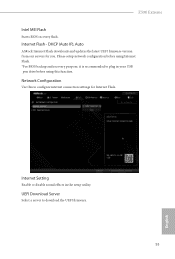
... configuration before using this to download the UEFI firmware. 93 English Network Configuration Use this function. Z590 Extreme Intel MEI Flash Starts BIOS recovery flash. DHCP (Auto IP), Auto ASRock Internet Flash downloads and updates the latest UEFI firmware version from our servers for Internet Flash. UEFI Download Server Select a server to configure internet connection settings for you. Internet Setting Enable or disable sound effects in your USB pen drive before using Internet Flash. *For BIOS backup and recovery purpose, it is recommended to plug in the setup utility...
... configuration before using this to download the UEFI firmware. 93 English Network Configuration Use this function. Z590 Extreme Intel MEI Flash Starts BIOS recovery flash. DHCP (Auto IP), Auto ASRock Internet Flash downloads and updates the latest UEFI firmware version from our servers for Internet Flash. UEFI Download Server Select a server to configure internet connection settings for you. Internet Setting Enable or disable sound effects in your USB pen drive before using Internet Flash. *For BIOS backup and recovery purpose, it is recommended to plug in the setup utility...

User Manual
Page 105
... Boot Use this option to change the password for the administrator account. Leave it blank and press enter to remove the password. 4.9 Security Screen In this section you may also clear the user password. Leave it blank and press enter to remove the password. Intel(R) Platform Trust Technology Enable/disable Intel PTT in the UEFI Setup Utility. User Password Set or change the supervisor/user password for Secure Boot. Users are unable to use discrete TPM Module. 98 English Supervisor Password Set...
... Boot Use this option to change the password for the administrator account. Leave it blank and press enter to remove the password. 4.9 Security Screen In this section you may also clear the user password. Leave it blank and press enter to remove the password. Intel(R) Platform Trust Technology Enable/disable Intel PTT in the UEFI Setup Utility. User Password Set or change the supervisor/user password for Secure Boot. Users are unable to use discrete TPM Module. 98 English Supervisor Password Set...

RAID Installation Guide
Page 7
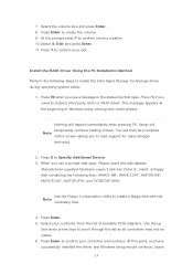
... a support CD to your USB storage device with RAID functions, please follow the procedures below. Enter UEFI SETUP UTILITY Tool and highlight "Easy RAID Installer". Follow the onscreen instruction to enter BIOS setup utility. STEP 4: Install Windows® 10 64-bit OS on your USB flash drive into a USB port B. Boot your system, and press key to complete the process. Please note that this document for all models A. Plug in your system. 7 STEP 1: Setting the BIOS RAID Items After installing the hard disk drives, please set SATA Mode...
... a support CD to your USB storage device with RAID functions, please follow the procedures below. Enter UEFI SETUP UTILITY Tool and highlight "Easy RAID Installer". Follow the onscreen instruction to enter BIOS setup utility. STEP 4: Install Windows® 10 64-bit OS on your USB flash drive into a USB port B. Boot your system, and press key to complete the process. Please note that this document for all models A. Plug in your system. 7 STEP 1: Setting the BIOS RAID Items After installing the hard disk drives, please set SATA Mode...

RAID Installation Guide
Page 23
... use Windows® 10 64-bit. STEP 1: Copy Intel® RAID drivers into a USB flash disk You can download the drivers from ASRock's website and unzip the files into a USB flash disk or copy the files from ASRock's motherboard support CD. (Please copy the files under the following directory: 32 bit: ..\i386\Win7_Intel.. 64-bit: ..\AMD64\Win7-64_Intel.. After the UEFI and RAID BIOS setup, please follow the steps below. 4. Installing Windows® on a HDD larger than 2TB in RAID mode Windows...
... use Windows® 10 64-bit. STEP 1: Copy Intel® RAID drivers into a USB flash disk You can download the drivers from ASRock's website and unzip the files into a USB flash disk or copy the files from ASRock's motherboard support CD. (Please copy the files under the following directory: 32 bit: ..\i386\Win7_Intel.. 64-bit: ..\AMD64\Win7-64_Intel.. After the UEFI and RAID BIOS setup, please follow the steps below. 4. Installing Windows® on a HDD larger than 2TB in RAID mode Windows...

RAID Installation Guide
Page 25
... hotfix kb2505454. (This may take more time to install motherboard drivers and utilities. 25 Windows® 10 64-bit: A. Disk volume > 2TB), it may take about 5 minutes to fix this hotfix then reboot by itself. Please request the hotfix KB2505454 through this link: http://support.microsoft.com/kb/2505454/ B. If you will install this problem. Please start to boot into Windows® or install driver/utilities.
... hotfix kb2505454. (This may take more time to install motherboard drivers and utilities. 25 Windows® 10 64-bit: A. Disk volume > 2TB), it may take about 5 minutes to fix this hotfix then reboot by itself. Please request the hotfix KB2505454 through this link: http://support.microsoft.com/kb/2505454/ B. If you will install this problem. Please start to boot into Windows® or install driver/utilities.
Intel Rapid Storage Guide
Page 13
... Enter. 11. Press Y to load support for mass storage device(s). 2. You will then be visible. 6. Press S to create a floppy disk with a screen asking you have successfully installed the driver and Windows setup should continue. At this point, you to confirm your controller and continue. This message appears at the beginning of available SCSI adapters. Use the up and down arrow keys to install the Intel Rapid Storage Technology driver...
... Enter. 11. Press Y to load support for mass storage device(s). 2. You will then be visible. 6. Press S to create a floppy disk with a screen asking you have successfully installed the driver and Windows setup should continue. At this point, you to confirm your controller and continue. This message appears at the beginning of available SCSI adapters. Use the up and down arrow keys to install the Intel Rapid Storage Technology driver...


