Intel Rapid Storage Guide
Page 12
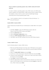
... the BIOS settings and exit the BIOS Setup program. When finished press Enter. 12 Enable RAID in System BIOS Use the instructions included with your motherboard to select the drive. Select the appropriate number of hard drives by using the up or down arrow keys to scroll through the list of...
... the BIOS settings and exit the BIOS Setup program. When finished press Enter. 12 Enable RAID in System BIOS Use the instructions included with your motherboard to select the drive. Select the appropriate number of hard drives by using the up or down arrow keys to scroll through the list of...
RAID Installation Guide
Page 2
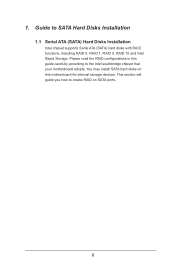
1. This section will guide you how to create RAID on this guide carefully according to SATA Hard Disks Installation 1.1 Serial ATA (SATA) Hard Disks Installation Intel chipset supports Serial ATA (SATA) hard disks with RAID functions, including RAID 0, RAID 1, RAID 5, RAID 10 and Intel Rapid Storage. Guide to the Intel southbridge chipset that your motherboard adopts. Please read the RAID configurations in this motherboard for internal storage devices. You may install SATA hard disks on SATA ports. 2
1. This section will guide you how to create RAID on this guide carefully according to SATA Hard Disks Installation 1.1 Serial ATA (SATA) Hard Disks Installation Intel chipset supports Serial ATA (SATA) hard disks with RAID functions, including RAID 0, RAID 1, RAID 5, RAID 10 and Intel Rapid Storage. Guide to the Intel southbridge chipset that your motherboard adopts. Please read the RAID configurations in this motherboard for internal storage devices. You may install SATA hard disks on SATA ports. 2
RAID Installation Guide
Page 3
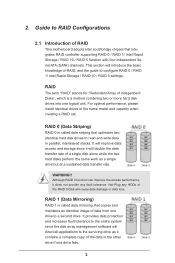
... if one logical unit. It will improve data access and storage since the disk array management software will introduce the basic knowledge of RAID This motherboard adopts Intel southbridge chipset that optimizes two identical hard disk drives to the surviving drive as a single drive but at a sustained data transfer rate. Guide...
... if one logical unit. It will improve data access and storage since the disk array management software will introduce the basic knowledge of RAID This motherboard adopts Intel southbridge chipset that optimizes two identical hard disk drives to the surviving drive as a single drive but at a sustained data transfer rate. Guide...
RAID Installation Guide
Page 23
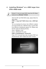
... steps below. STEP 1: Copy Intel® RAID drivers into a USB flash disk You can download the drivers from ASRock's website and unzip the files into a USB flash disk or copy the files from ASRock's motherboard support CD. (Please copy the files under the following directory: 32 bit: ..\i386\Win7_Intel.. 64-bit: ..\AMD64\Win7...
... steps below. STEP 1: Copy Intel® RAID drivers into a USB flash disk You can download the drivers from ASRock's website and unzip the files into a USB flash disk or copy the files from ASRock's motherboard support CD. (Please copy the files under the following directory: 32 bit: ..\i386\Win7_Intel.. 64-bit: ..\AMD64\Win7...
RAID Installation Guide
Page 25
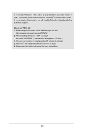
... instructions below to boot into Windows® or install driver/utilities. Please start to reboot.) D. E. Reboot your system. (It may take about 5 minutes to install motherboard drivers and utilities. 25 If you will install this hotfix then reboot by itself. Windows® 10 64-bit: A.
... instructions below to boot into Windows® or install driver/utilities. Please start to reboot.) D. E. Reboot your system. (It may take about 5 minutes to install motherboard drivers and utilities. 25 If you will install this hotfix then reboot by itself. Windows® 10 64-bit: A.
User Manual
Page 2
...Best Management Practices (BMP) regulations passed by ASRock. "Perchlorate Material-special handling may cause undesired operation. Version 1.1 Published May 2020 Copyright©2020 ASRock INC. All rights reserved. Products and corporate names appearing in this motherboard contains Perchlorate, a toxic substance controlled in ...damages for loss of profits, loss of business, loss of data, interruption of business and the like), even if ASRock has been advised of the possibility of merchantability or fitness for backup purpose, without written consent of this documentation may appear ...
...Best Management Practices (BMP) regulations passed by ASRock. "Perchlorate Material-special handling may cause undesired operation. Version 1.1 Published May 2020 Copyright©2020 ASRock INC. All rights reserved. Products and corporate names appearing in this motherboard contains Perchlorate, a toxic substance controlled in ...damages for loss of profits, loss of business, loss of data, interruption of business and the like), even if ASRock has been advised of the possibility of merchantability or fitness for backup purpose, without written consent of this documentation may appear ...
User Manual
Page 4
Contents Chapter 1 Introduction 1 1.1 Package Contents 1 1.2 Specifications 2 1.3 Motherboard Layout 7 1.4 I/O Panel 9 Chapter 2 Installation 10 2.1 Installing the CPU 11 2.2 Installing the CPU Fan and Heatsink 14 2.3 Installing Memory Modules (DIMM) 15 2.4 Expansion Slots (PCI Express ... 28 2.9 M.2_SSD (NGFF) Module Installation Guide (M2_1) 30 2.10 M.2_SSD (NGFF) Module Installation Guide (M2_2) 33 Chapter 3 Software and Utilities Operation 37 3.1 Installing Drivers 37 3.2 ASRock Motherboard Utility (A-Tuning) 38
Contents Chapter 1 Introduction 1 1.1 Package Contents 1 1.2 Specifications 2 1.3 Motherboard Layout 7 1.4 I/O Panel 9 Chapter 2 Installation 10 2.1 Installing the CPU 11 2.2 Installing the CPU Fan and Heatsink 14 2.3 Installing Memory Modules (DIMM) 15 2.4 Expansion Slots (PCI Express ... 28 2.9 M.2_SSD (NGFF) Module Installation Guide (M2_1) 30 2.10 M.2_SSD (NGFF) Module Installation Guide (M2_2) 33 Chapter 3 Software and Utilities Operation 37 3.1 Installing Drivers 37 3.2 ASRock Motherboard Utility (A-Tuning) 38
User Manual
Page 7
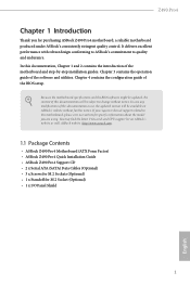
... cards and CPU support list on ASRock's website without notice. ASRock website http://www.asrock.com. 1.1 Package Contents • ASRock Z490 Pro4 Motherboard (ATX Form Factor) • ASRock Z490 Pro4 Quick Installation Guide • ASRock Z490 Pro4 Support CD • 2 x Serial ATA (SATA) Data Cables (Optional) • 3 x Screws for M.2 Sockets (Optional) • 1 x Standoff for purchasing ASRock Z490 Pro4 motherboard, a reliable motherboard produced under ASRock's consistently stringent quality control. If...
... cards and CPU support list on ASRock's website without notice. ASRock website http://www.asrock.com. 1.1 Package Contents • ASRock Z490 Pro4 Motherboard (ATX Form Factor) • ASRock Z490 Pro4 Quick Installation Guide • ASRock Z490 Pro4 Support CD • 2 x Serial ATA (SATA) Data Cables (Optional) • 3 x Screws for M.2 Sockets (Optional) • 1 x Standoff for purchasing ASRock Z490 Pro4 motherboard, a reliable motherboard produced under ASRock's consistently stringent quality control. If...
User Manual
Page 13
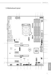
USB 2.0 T: USB_1 B: USB_2 PS2 Keyboard /Mouse 1.3 Motherboard Layout 1 2 ATX12V1 ATX12V2 Z490 Pro4 34 56 CPU_FAN1 CPU_FAN2/WP 7 ADDR_LED2 8 1 1 RGB_LED2 HDMI1 Z490 PRO4 DDR4_A1 (64 bit, 288-pin module) DDR4_A2 (64 bit, 288-pin module) DDR4_B1 (64 bit, 288-pin module) DDR4_B2... T B1 1 RoHS CT4 PCIE5 CT5 CT6 COM1 1 RGB_LED1 1 ADDR_LED1 1 USB_3_4 1 1 USB3_5_6 1 CLRMOS1 CHA_FAN3/WP CHA_FAN1/WP SATA3_0 1 Intel Z490 M2_2 CHA_FAN4/WP SPK_PLED1 1 PANEL1 PLED PWRBTN SPI_TPM_J1 1 SATA3_4 1 HDLED RESET SATA3_5 USB3_3_4 27 26 25 24 23 22 21 20 19 SATA3_2 SATA3_3 ...
USB 2.0 T: USB_1 B: USB_2 PS2 Keyboard /Mouse 1.3 Motherboard Layout 1 2 ATX12V1 ATX12V2 Z490 Pro4 34 56 CPU_FAN1 CPU_FAN2/WP 7 ADDR_LED2 8 1 1 RGB_LED2 HDMI1 Z490 PRO4 DDR4_A1 (64 bit, 288-pin module) DDR4_A2 (64 bit, 288-pin module) DDR4_B1 (64 bit, 288-pin module) DDR4_B2... T B1 1 RoHS CT4 PCIE5 CT5 CT6 COM1 1 RGB_LED1 1 ADDR_LED1 1 USB_3_4 1 1 USB3_5_6 1 CLRMOS1 CHA_FAN3/WP CHA_FAN1/WP SATA3_0 1 Intel Z490 M2_2 CHA_FAN4/WP SPK_PLED1 1 PANEL1 PLED PWRBTN SPI_TPM_J1 1 SATA3_4 1 HDLED RESET SATA3_5 USB3_3_4 27 26 25 24 23 22 21 20 19 SATA3_2 SATA3_3 ...
User Manual
Page 16
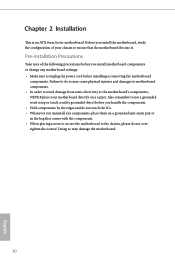
...not overtighten the screws! Chapter 2 Installation This is an ATX form factor motherboard. Pre-installation Precautions Take note of your motherboard directly on a grounded anti-static pad or in the bag that the motherboard fits into it. Also remember to use a grounded wrist strap or touch ...touch the ICs. • Whenever you install motherboard components or change any motherboard settings. • Make sure to the chassis, please do so may damage the motherboard. 10 English Doing so may cause physical injuries and damages to motherboard components. • In order to avoid damage...
...not overtighten the screws! Chapter 2 Installation This is an ATX form factor motherboard. Pre-installation Precautions Take note of your motherboard directly on a grounded anti-static pad or in the bag that the motherboard fits into it. Also remember to use a grounded wrist strap or touch ...touch the ICs. • Whenever you install motherboard components or change any motherboard settings. • Make sure to the chassis, please do so may damage the motherboard. 10 English Doing so may cause physical injuries and damages to motherboard components. • In order to avoid damage...
User Manual
Page 19
The cover must be placed if you wish to return the motherboard for after service. 13 English Z490 Pro4 Please save and replace the cover if the processor is removed.
The cover must be placed if you wish to return the motherboard for after service. 13 English Z490 Pro4 Please save and replace the cover if the processor is removed.
User Manual
Page 21
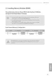
... Configuration Priority 1 2 DDR4_A1 Populated DDR4_A2 Populated Populated DDR4_B1 Populated DDR4_B2 Populated Populated The DIMM only fits in one or three memory module installed. 3. Z490 Pro4 2.3 Installing Memory Modules (DIMM) This motherboard provides four 288-pin DDR4 (Double Data Rate 4) DIMM slots, and supports Dual Channel Memory Technology. 1. For dual channel configuration, you force...
... Configuration Priority 1 2 DDR4_A1 Populated DDR4_A2 Populated Populated DDR4_B1 Populated DDR4_B2 Populated Populated The DIMM only fits in one or three memory module installed. 3. Z490 Pro4 2.3 Installing Memory Modules (DIMM) This motherboard provides four 288-pin DDR4 (Double Data Rate 4) DIMM slots, and supports Dual Channel Memory Technology. 1. For dual channel configuration, you force...
User Manual
Page 23
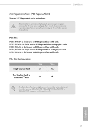
... For a better thermal environment, please connect a chassis fan to the motherboard's chassis fan connector (CHA_FAN1/WP, CHA_FAN2/WP, CHA_FAN3/WP or CHA_FAN4/WP) when using multiple graphics cards. Z490 Pro4 2.4 Expansion Slots (PCI Express Slots) There are 5 PCI Express slots on the motherboard. Before installing an expansion card, please make necessary hardware settings for...
... For a better thermal environment, please connect a chassis fan to the motherboard's chassis fan connector (CHA_FAN1/WP, CHA_FAN2/WP, CHA_FAN3/WP or CHA_FAN4/WP) when using multiple graphics cards. Z490 Pro4 2.4 Expansion Slots (PCI Express Slots) There are 5 PCI Express slots on the motherboard. Before installing an expansion card, please make necessary hardware settings for...
User Manual
Page 25
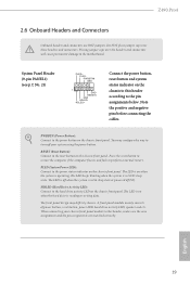
... (Power Button): Connect to the motherboard. HDLED (Hard Drive Activity LED): Connect to the hard drive activity LED on the chassis front panel. The front panel design may configure the way to this header according to the power status indicator on the chassis front panel. Z490 Pro4 2.6 Onboard Headers and Connectors Onboard headers...
... (Power Button): Connect to the motherboard. HDLED (Hard Drive Activity LED): Connect to the hard drive activity LED on the chassis front panel. The front panel design may configure the way to this header according to the power status indicator on the chassis front panel. Z490 Pro4 2.6 Onboard Headers and Connectors Onboard headers...
User Manual
Page 26
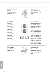
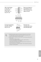
...) (see p.7, No. 19) SATA3_2 SATA3_0 SATA3_3 SATA3_1 SATA3_4 SATA3_5 These six SATA3 connectors support SATA data cables for internal storage devices with up to this motherboard. USB 2.0 Header (9-pin USB_3_4) (see p.7, No. 24) USB_PWR PP+ GND DUMMY 1 GND P+ PUSB_PWR There is occupied by a PCIe-type M.2 device, SATA3_0 will be disabled. Each...
...) (see p.7, No. 19) SATA3_2 SATA3_0 SATA3_3 SATA3_1 SATA3_4 SATA3_5 These six SATA3 connectors support SATA data cables for internal storage devices with up to this motherboard. USB 2.0 Header (9-pin USB_3_4) (see p.7, No. 24) USB_PWR PP+ GND DUMMY 1 GND P+ PUSB_PWR There is occupied by a PCIe-type M.2 device, SATA3_0 will be disabled. Each...
User Manual
Page 27
High Definition Audio supports Jack Sensing, but the panel wire on this motherboard. If you use an AC'97 audio panel, please install it to function correctly. D. To activate the front mic, go to Ground (GND). Vbus IntA_PA_SSRXIntA_PA_SSRX+ ... MIC2_L. MIC_RET and OUT_RET are two headers on the chassis must support HDA to the front panel audio header by the steps below: A. English 21 Z490 Pro4 USB 3.2 Gen1 Headers (19-pin USB3_3_4) (see p.7, No. 10) (19-pin USB3_5_6) (see p.7, No. 27) GND PRESENCE# MIC_RET OUT_RET 1 OUT2_L J_SENSE OUT2_R MIC2_R MIC2_L This...
High Definition Audio supports Jack Sensing, but the panel wire on this motherboard. If you use an AC'97 audio panel, please install it to function correctly. D. To activate the front mic, go to Ground (GND). Vbus IntA_PA_SSRXIntA_PA_SSRX+ ... MIC2_L. MIC_RET and OUT_RET are two headers on the chassis must support HDA to the front panel audio header by the steps below: A. English 21 Z490 Pro4 USB 3.2 Gen1 Headers (19-pin USB3_3_4) (see p.7, No. 10) (19-pin USB3_5_6) (see p.7, No. 27) GND PRESENCE# MIC_RET OUT_RET 1 OUT2_L J_SENSE OUT2_R MIC2_R MIC2_L This...
User Manual
Page 28
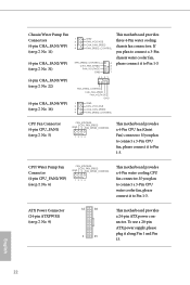
...GND 2 FAN_VOLTAGE 3 CHA_FAN_SPEED 4 FAN_SPEED_CONTROL CPU Fan Connector (4-pin CPU_FAN1) (see p.7, No. 6) FAN_VOLTAGE CPU_FAN_SPEED GND FAN_SPEED_CONTROL 1 2 3 4 This motherboard provides a 4-Pin water cooling CPU fan connector. ATX Power Connector (24-pin ATXPWR1) (see p.7, No. 16) 1 GND 2 FAN_VOLTAGE 3... CHA_FAN_SPEED 4 FAN_SPEED_CONTROL FAN_SPEED_CONTROL 4 CHA_FAN_SPEED 3 FAN_VOLTAGE 2 GND 1 43 21 This motherboard provides three 4-Pin water cooling chassis fan connectors. If you plan to Pin 1-3. To use a 20-pin ATX ...
...GND 2 FAN_VOLTAGE 3 CHA_FAN_SPEED 4 FAN_SPEED_CONTROL CPU Fan Connector (4-pin CPU_FAN1) (see p.7, No. 6) FAN_VOLTAGE CPU_FAN_SPEED GND FAN_SPEED_CONTROL 1 2 3 4 This motherboard provides a 4-Pin water cooling CPU fan connector. ATX Power Connector (24-pin ATXPWR1) (see p.7, No. 16) 1 GND 2 FAN_VOLTAGE 3... CHA_FAN_SPEED 4 FAN_SPEED_CONTROL FAN_SPEED_CONTROL 4 CHA_FAN_SPEED 3 FAN_VOLTAGE 2 GND 1 43 21 This motherboard provides three 4-Pin water cooling chassis fan connectors. If you plan to Pin 1-3. To use a 20-pin ATX ...
User Manual
Page 29
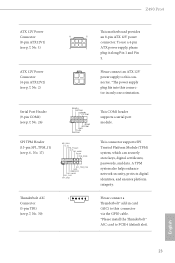
Serial Port Header (9-pin COM1) (see p.7, No. 26) SPI TPM Header (13-pin SPI_TPM_J1) (see p.7, No. 2) This motherboard provides 8 5 an 8-pin ATX 12V power connector. This connector supports SPI Trusted Platform Module (TPM) system, which can securely store keys, digital ... fits into this connector in card (AIC) to this connector via the GPIO cable. *Please install the Thunderbolt™ AIC card to PCIE4 (default slot). Z490 Pro4 ATX 12V Power Connector (8-pin ATX12V1) (see p.7, No. 1) ATX 12V Power Connector (4-pin ATX12V2) (see p.6, No. 17) RRXD1 DDTR#1 DDSR#1 CCTS#1 1 RRI#1...
Serial Port Header (9-pin COM1) (see p.7, No. 26) SPI TPM Header (13-pin SPI_TPM_J1) (see p.7, No. 2) This motherboard provides 8 5 an 8-pin ATX 12V power connector. This connector supports SPI Trusted Platform Module (TPM) system, which can securely store keys, digital ... fits into this connector in card (AIC) to this connector via the GPIO cable. *Please install the Thunderbolt™ AIC card to PCIE4 (default slot). Z490 Pro4 ATX 12V Power Connector (8-pin ATX12V1) (see p.7, No. 1) ATX 12V Power Connector (4-pin ATX12V2) (see p.6, No. 17) RRXD1 DDTR#1 DDSR#1 CCTS#1 1 RRI#1...
User Manual
Page 31
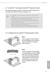
... of the graphics cards. (The CrossFire Bridge is recommended to your graphics card vendor for details. 4. Z490 Pro4 2.7 CrossFireXTM and Quad CrossFireXTM Operation Guide This motherboard supports CrossFireXTM and Quad CrossFireXTM that allows you to install up to PCIE4 slot. Please refer to AMD ...cards may require different methods to the AMD's website for details.) English 25 If you pair a 12-pipe CrossFireXTM Edition card with this motherboard. Make sure that the cards are AMD certified. 2. Please refer to enable CrossFireXTM. Download the drivers from the AMD's website: www...
... of the graphics cards. (The CrossFire Bridge is recommended to your graphics card vendor for details. 4. Z490 Pro4 2.7 CrossFireXTM and Quad CrossFireXTM Operation Guide This motherboard supports CrossFireXTM and Quad CrossFireXTM that allows you to install up to PCIE4 slot. Please refer to AMD ...cards may require different methods to the AMD's website for details.) English 25 If you pair a 12-pipe CrossFireXTM Edition card with this motherboard. Make sure that the cards are AMD certified. 2. Please refer to enable CrossFireXTM. Download the drivers from the AMD's website: www...
User Manual
Page 37
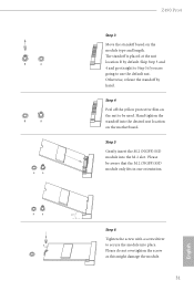
... the default nut. Please do not overtighten the screw as this might damage the module. 31 Step 4 Peel off the yellow protective film on the motherboard. B A B A B A Z490 Pro4 Step 3 Move the standoff based on the module type and length. The standoff is placed at the nut location B by hand.
... the default nut. Please do not overtighten the screw as this might damage the module. 31 Step 4 Peel off the yellow protective film on the motherboard. B A B A B A Z490 Pro4 Step 3 Move the standoff based on the module type and length. The standoff is placed at the nut location B by hand.

