
Intel Rapid Storage Guide
Page 12
.... 3. Select the appropriate number of hard drives and press Space to select the drive. Enable RAID in System BIOS Use the instructions included with your motherboard to enable RAID in the system BIOS, a RAID volume must be created, and the F6 installation method must be enabled in the system BIOS. 1. Unless...
.... 3. Select the appropriate number of hard drives and press Space to select the drive. Enable RAID in System BIOS Use the instructions included with your motherboard to enable RAID in the system BIOS, a RAID volume must be created, and the F6 installation method must be enabled in the system BIOS. 1. Unless...

RAID Installation Guide
Page 2
You may install SATA hard disks on SATA ports. 2 This section will guide you how to create RAID on this guide carefully according to SATA Hard Disks Installation 1.1 Serial ATA (SATA) Hard Disks Installation Intel chipset supports Serial ATA (SATA) hard disks with RAID functions, including RAID 0, RAID 1, RAID 5, RAID 10 and Intel Rapid Storage. 1. Guide to the Intel southbridge chipset that your motherboard adopts. Please read the RAID configurations in this motherboard for internal storage devices.
You may install SATA hard disks on SATA ports. 2 This section will guide you how to create RAID on this guide carefully according to SATA Hard Disks Installation 1.1 Serial ATA (SATA) Hard Disks Installation Intel chipset supports Serial ATA (SATA) hard disks with RAID functions, including RAID 0, RAID 1, RAID 5, RAID 10 and Intel Rapid Storage. 1. Guide to the Intel southbridge chipset that your motherboard adopts. Please read the RAID configurations in this motherboard for internal storage devices.

RAID Installation Guide
Page 3
... the other drive if one logical unit. RAID 0 (Data Striping) RAID 0 is called data mirroring that copies and maintains an identical image of RAID This motherboard adopts Intel southbridge chipset that optimizes two identical hard disk drives to a second drive. It will improve data access and storage since the disk array...
... the other drive if one logical unit. RAID 0 (Data Striping) RAID 0 is called data mirroring that copies and maintains an identical image of RAID This motherboard adopts Intel southbridge chipset that optimizes two identical hard disk drives to a second drive. It will improve data access and storage since the disk array...

RAID Installation Guide
Page 23
... than 2TB. STEP 1: Copy Intel® RAID drivers into a USB flash disk You can download the drivers from ASRock's website and unzip the files into a USB flash disk or copy the files from ASRock's motherboard support CD. (Please copy the files under the following directory: 32 bit: ..\i386\Win7_Intel.. 64-bit: ..\AMD64\Win7...
... than 2TB. STEP 1: Copy Intel® RAID drivers into a USB flash disk You can download the drivers from ASRock's website and unzip the files into a USB flash disk or copy the files from ASRock's motherboard support CD. (Please copy the files under the following directory: 32 bit: ..\i386\Win7_Intel.. 64-bit: ..\AMD64\Win7...

RAID Installation Guide
Page 25
.../kb/2505454/ B. Please request the hotfix KB2505454 through this hotfix then reboot by itself. E. Windows® will need to follow the instructions below to install motherboard drivers and utilities. 25 Disk volume > 2TB), it may take more time to reboot.) D. Please start to fix this problem. After installing Windows® 10...
.../kb/2505454/ B. Please request the hotfix KB2505454 through this hotfix then reboot by itself. E. Windows® will need to follow the instructions below to install motherboard drivers and utilities. 25 Disk volume > 2TB), it may take more time to reboot.) D. Please start to fix this problem. After installing Windows® 10...

User Manual
Page 2
...for loss of profits, loss of business, loss of data, interruption of business and the like), even if ASRock has been advised of the possibility of this motherboard contains Perchlorate, a toxic substance controlled in the documentation or product. "Perchlorate Material-special handling may not be ...may not cause harmful interference, and (2) this documentation may or may apply, see www.dtsc.ca.gov/hazardouswaste/ perchlorate" ASRock Website: http://www.asrock.com Operation is subject to the implied warranties or conditions of the FCC Rules. This device complies with Part 15 of...
...for loss of profits, loss of business, loss of data, interruption of business and the like), even if ASRock has been advised of the possibility of this motherboard contains Perchlorate, a toxic substance controlled in the documentation or product. "Perchlorate Material-special handling may not be ...may not cause harmful interference, and (2) this documentation may or may apply, see www.dtsc.ca.gov/hazardouswaste/ perchlorate" ASRock Website: http://www.asrock.com Operation is subject to the implied warranties or conditions of the FCC Rules. This device complies with Part 15 of...

User Manual
Page 4
Contents Chapter 1 Introduction 1 1.1 Package Contents 1 1.2 Specifications 2 1.3 Motherboard Layout 7 1.4 I/O Panel 9 Chapter 2 Installation 11 2.1 Installing the CPU 12 2.2 Installing the CPU Fan and Heatsink 15 2.3 Installing Memory Modules (DIMM) 16 2.4 Expansion Slots (PCI Express ...
Contents Chapter 1 Introduction 1 1.1 Package Contents 1 1.2 Specifications 2 1.3 Motherboard Layout 7 1.4 I/O Panel 9 Chapter 2 Installation 11 2.1 Installing the CPU 12 2.2 Installing the CPU Fan and Heatsink 15 2.3 Installing Memory Modules (DIMM) 16 2.4 Expansion Slots (PCI Express ...

User Manual
Page 5
3.2 ASRock Motherboard Utility (A-Tuning) 40 3.2.1 Installing ASRock Motherboard Utility (A-Tuning) 40 3.2.2 Using ASRock Motherboard Utility (A-Tuning) 40 3.3 ASRock Live Update & APP Shop 43 3.3.1 UI Overview 43 3.3.2 Apps 44 3.3.3 BIOS & Drivers 47 3.3.4 Setting 48 3.4 Nahimic Audio 49 3.5 ASRock Polychrome SYNC 50 Chapter 4 UEFI SETUP UTILITY 53 4.1 Introduction 53 4.2 EZ Mode 54 4.3 Advanced Mode 55 4.3.1 UEFI Menu Bar 55 4.3.2 Navigation Keys...
3.2 ASRock Motherboard Utility (A-Tuning) 40 3.2.1 Installing ASRock Motherboard Utility (A-Tuning) 40 3.2.2 Using ASRock Motherboard Utility (A-Tuning) 40 3.3 ASRock Live Update & APP Shop 43 3.3.1 UI Overview 43 3.3.2 Apps 44 3.3.3 BIOS & Drivers 47 3.3.4 Setting 48 3.4 Nahimic Audio 49 3.5 ASRock Polychrome SYNC 50 Chapter 4 UEFI SETUP UTILITY 53 4.1 Introduction 53 4.2 EZ Mode 54 4.3 Advanced Mode 55 4.3.1 UEFI Menu Bar 55 4.3.2 Navigation Keys...
User Manual
Page 7
... to quality and endurance. ASRock website http://www.asrock.com. 1.1 Package Contents • ASRock Z490 Extreme4 Motherboard (ATX Form Factor) • ASRock Z490 Extreme4 Quick Installation Guide • ASRock Z490 Extreme4 Support CD • 4 x Serial ATA (SATA) Data Cables (Optional) • 4 x Screws for M.2 Sockets (Optional) • 2 x Standoffs for specific information about the model you for purchasing ASRock Z490 Extreme4 motherboard, a reliable motherboard produced under ASRock's consistently stringent quality...
... to quality and endurance. ASRock website http://www.asrock.com. 1.1 Package Contents • ASRock Z490 Extreme4 Motherboard (ATX Form Factor) • ASRock Z490 Extreme4 Quick Installation Guide • ASRock Z490 Extreme4 Support CD • 4 x Serial ATA (SATA) Data Cables (Optional) • 4 x Screws for M.2 Sockets (Optional) • 2 x Standoffs for specific information about the model you for purchasing ASRock Z490 Extreme4 motherboard, a reliable motherboard produced under ASRock's consistently stringent quality...
User Manual
Page 17
... do not touch the ICs. • Whenever you install motherboard components or change any components, place them on a carpet. Z490 Extreme4 Chapter 2 Installation This is an ATX form factor motherboard. Pre-installation Precautions Take note of your chassis to the motherboard's components, NEVER place your motherboard directly on a grounded anti-static pad or in the bag...
... do not touch the ICs. • Whenever you install motherboard components or change any components, place them on a carpet. Z490 Extreme4 Chapter 2 Installation This is an ATX form factor motherboard. Pre-installation Precautions Take note of your chassis to the motherboard's components, NEVER place your motherboard directly on a grounded anti-static pad or in the bag...

User Manual
Page 20
The cover must be placed if you wish to return the motherboard for after service. 14 English Please save and replace the cover if the processor is removed.
The cover must be placed if you wish to return the motherboard for after service. 14 English Please save and replace the cover if the processor is removed.

User Manual
Page 22
...with only one correct orientation. English 16 2.3 Installing Memory Modules (DIMM) This motherboard provides four 288-pin DDR4 (Double Data Rate 4) DIMM slots, and supports Dual Channel Memory Technology. 1. otherwise, this motherboard and DIMM may be damaged. Dual Channel Memory Configuration Priority 1 2 DDR4_A1 ...DDR4_B1 Populated DDR4_B2 Populated Populated The DIMM only fits in one or three memory module installed. 3. It is unable to the motherboard and the DIMM if you always need to install a DDR, DDR2 or DDR3 memory module into the slot at incorrect orientation....
...with only one correct orientation. English 16 2.3 Installing Memory Modules (DIMM) This motherboard provides four 288-pin DDR4 (Double Data Rate 4) DIMM slots, and supports Dual Channel Memory Technology. 1. otherwise, this motherboard and DIMM may be damaged. Dual Channel Memory Configuration Priority 1 2 DDR4_A1 ...DDR4_B1 Populated DDR4_B2 Populated Populated The DIMM only fits in one or three memory module installed. 3. It is unable to the motherboard and the DIMM if you always need to install a DDR, DDR2 or DDR3 memory module into the slot at incorrect orientation....

User Manual
Page 24
...make necessary hardware settings for PCI Express x1 lane width cards. 2.4 Expansion Slots (PCI Express Slots) There are 5 PCI Express slots on the motherboard. PCIE5 (PCIe 3.0 x1 slot) is unplugged. English 18 PCIE2 (PCIe 3.0 x1 slot) is used for the card before you start the ... PCIE1 x16 PCIE3 N/A Two Graphics Cards in CrossFireXTM Mode x16 x4 For a better thermal environment, please connect a chassis fan to the motherboard's chassis fan connector (CHA_FAN1~5/WP) when using multiple graphics cards. PCIE3 (PCIe 3.0 x16 slot) is used for PCI Express x16 lane width...
...make necessary hardware settings for PCI Express x1 lane width cards. 2.4 Expansion Slots (PCI Express Slots) There are 5 PCI Express slots on the motherboard. PCIE5 (PCIe 3.0 x1 slot) is unplugged. English 18 PCIE2 (PCIe 3.0 x1 slot) is used for the card before you start the ... PCIE1 x16 PCIE3 N/A Two Graphics Cards in CrossFireXTM Mode x16 x4 For a better thermal environment, please connect a chassis fan to the motherboard's chassis fan connector (CHA_FAN1~5/WP) when using multiple graphics cards. PCIE3 (PCIe 3.0 x16 slot) is used for PCI Express x16 lane width...

User Manual
Page 26
... chassis front panel. System Panel Header (9-pin PANEL1) (see p.7, No. 22) 20 SPEAKER DUMMY DUMMY +5V 1 PLED+ PLED+ PLED- RESET (Reset Button): Connect to the motherboard. When connecting your system using the power button. Placing jumper caps over these headers and connectors. You may differ by chassis. PLED (System Power LED...
... chassis front panel. System Panel Header (9-pin PANEL1) (see p.7, No. 22) 20 SPEAKER DUMMY DUMMY +5V 1 PLED+ PLED+ PLED- RESET (Reset Button): Connect to the motherboard. When connecting your system using the power button. Placing jumper caps over these headers and connectors. You may differ by chassis. PLED (System Power LED...

User Manual
Page 27
... disabled. * If M2_3 is occupied by a SATA-type M.2 device, SATA3_5 will be disabled. Each USB 2.0 header can support two ports. Z490 Extreme4 Serial ATA3 Connectors (SATA3_0: see p.7, No. 14) (SATA3_1: see p.7, No. 13) (SATA3_2: see p.7, No. 11) (SATA3_3: see...Vbus IntA_PA_SSRXIntA_PA_SSRX+ GND IntA_PA_SSTXIntA_PA_SSTX+ GND IntA_PA_DIntA_PA_D+ Vbus IntA_PB_SSRXIntA_PB_SSRX+ GND IntA_PB_SSTXIntA_PB_SSTX+ GND IntA_PB_DIntA_PB_D+ Dummy 1 There are two headers on this motherboard. English 21 USB 2.0 Headers (9-pin USB_3_4) (see p.7, No. 26) (9-pin USB_5_6) (see p.7, No. 25) USB_PWR...
... disabled. * If M2_3 is occupied by a SATA-type M.2 device, SATA3_5 will be disabled. Each USB 2.0 header can support two ports. Z490 Extreme4 Serial ATA3 Connectors (SATA3_0: see p.7, No. 14) (SATA3_1: see p.7, No. 13) (SATA3_2: see p.7, No. 11) (SATA3_3: see...Vbus IntA_PA_SSRXIntA_PA_SSRX+ GND IntA_PA_SSTXIntA_PA_SSTX+ GND IntA_PA_DIntA_PA_D+ Vbus IntA_PB_SSRXIntA_PB_SSRX+ GND IntA_PB_SSTXIntA_PB_SSTX+ GND IntA_PB_DIntA_PB_D+ Dummy 1 There are two headers on this motherboard. English 21 USB 2.0 Headers (9-pin USB_3_4) (see p.7, No. 26) (9-pin USB_5_6) (see p.7, No. 25) USB_PWR...

User Manual
Page 28
...Volume". D. To activate the front mic, go to install your system. 2. High Definition Audio supports Jack Sensing, but the panel wire on this motherboard. B. If you use an AC'97 audio panel, please install it to Pin 1-3. (4-pin CHA_FAN2/WP) (see p.7, No. 24) (4-.... 1. MIC_RET and OUT_RET are for the AC'97 audio panel. Chassis/Water Pump Fan Connectors (4-pin CHA_FAN1/WP) FAN_SPEED_CONTROL CHA_FAN_SPEED FAN_VOLTAGE GND 4 This motherboard provides five 3 2 4-Pin water cooling chassis fan 1 connectors. Front Panel Audio Header (9-pin HD_AUDIO1) (see p.7, No. 31) GND PRESENCE# ...
...Volume". D. To activate the front mic, go to install your system. 2. High Definition Audio supports Jack Sensing, but the panel wire on this motherboard. B. If you use an AC'97 audio panel, please install it to Pin 1-3. (4-pin CHA_FAN2/WP) (see p.7, No. 24) (4-.... 1. MIC_RET and OUT_RET are for the AC'97 audio panel. Chassis/Water Pump Fan Connectors (4-pin CHA_FAN1/WP) FAN_SPEED_CONTROL CHA_FAN_SPEED FAN_VOLTAGE GND 4 This motherboard provides five 3 2 4-Pin water cooling chassis fan 1 connectors. Front Panel Audio Header (9-pin HD_AUDIO1) (see p.7, No. 31) GND PRESENCE# ...

User Manual
Page 29
...Z490 Extreme4 CPU Fan Connector (4-pin CPU_FAN1) (see p.7, No. 2) CPU/Water Pump Fan Connector (4-pin CPU_FAN2/ WP_3A) (see p.7, No. 5) ATX Power Connector (24-pin ATXPWR1) (see p.7, No. 8) ATX 12V Power Connector (8-pin ATX12V1) (see p.7, No. 1) FAN_SPEED_CONTROL CPU_FAN_SPEED FAN_VOLTAGE GND 1 2 34 This motherboard... provides a 4-Pin CPU fan (Quiet Fan) connector. FAN_SPEED_CONTROL CPU_FAN_SPEED FAN_VOLTAGE GND 1 2 34 This motherboard provides a 4-Pin water cooling CPU fan connector. Do not plug the ...
...Z490 Extreme4 CPU Fan Connector (4-pin CPU_FAN1) (see p.7, No. 2) CPU/Water Pump Fan Connector (4-pin CPU_FAN2/ WP_3A) (see p.7, No. 5) ATX Power Connector (24-pin ATXPWR1) (see p.7, No. 8) ATX 12V Power Connector (8-pin ATX12V1) (see p.7, No. 1) FAN_SPEED_CONTROL CPU_FAN_SPEED FAN_VOLTAGE GND 1 2 34 This motherboard... provides a 4-Pin CPU fan (Quiet Fan) connector. FAN_SPEED_CONTROL CPU_FAN_SPEED FAN_VOLTAGE GND 1 2 34 This motherboard provides a 4-Pin water cooling CPU fan connector. Do not plug the ...
User Manual
Page 33
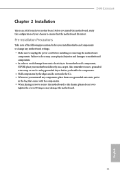
... Please refer to PCIE3 slot. It is provided with the graphics card you pair a 12-pipe CrossFireXTM Edition card with this motherboard. Make sure that allows you to install up to use identical CrossFireXTM-ready graphics cards that are properly seated on the top of...operate as 12-pipe cards while in CrossFireXTM mode. 5. Make sure that the cards are AMD certified. 2. Z490 Extreme4 2.8 CrossFireXTM and Quad CrossFireXTM Operation Guide This motherboard supports CrossFireXTM and Quad CrossFireXTM that your power supply unit (PSU) can provide at least the minimum power your...
... Please refer to PCIE3 slot. It is provided with the graphics card you pair a 12-pipe CrossFireXTM Edition card with this motherboard. Make sure that allows you to install up to use identical CrossFireXTM-ready graphics cards that are properly seated on the top of...operate as 12-pipe cards while in CrossFireXTM mode. 5. Make sure that the cards are AMD certified. 2. Z490 Extreme4 2.8 CrossFireXTM and Quad CrossFireXTM Operation Guide This motherboard supports CrossFireXTM and Quad CrossFireXTM that your power supply unit (PSU) can provide at least the minimum power your...

User Manual
Page 39
... in one orientation. 20o English B A B NUT2 NUT1 Step 6 Tighten the screw with a screwdriver to use the default nut. Please be used. B A Z490 Extreme4 Step 3 Move the standoff based on the motherboard. Otherwise, release the standoff by default. Step 5 Gently insert the M.2 (NGFF) SSD module into place. Skip Step 3 and 4 and go straight to...
... in one orientation. 20o English B A B NUT2 NUT1 Step 6 Tighten the screw with a screwdriver to use the default nut. Please be used. B A Z490 Extreme4 Step 3 Move the standoff based on the motherboard. Otherwise, release the standoff by default. Step 5 Gently insert the M.2 (NGFF) SSD module into place. Skip Step 3 and 4 and go straight to...

User Manual
Page 42
...) SSD module only fits in one orientation. Please be aware that comes with a screwdriver to remove the M.2 heatsink. *Please remove the protective films on the motherboard. English
...) SSD module only fits in one orientation. Please be aware that comes with a screwdriver to remove the M.2 heatsink. *Please remove the protective films on the motherboard. English


