
User Manual
Page 28
... Connectors (4-pin CHA_FAN1/WP) FAN_SPEED_CONTROL CHA_FAN_SPEED FAN_VOLTAGE GND 4 This motherboard provides five 3 2 4-Pin water cooling chassis fan 1 connectors. Please follow the instructions in our manual and chassis manual to the "FrontMic" Tab in the Realtek Control panel and adjust "Recording Volume". B. D. To activate the front mic, go to install your system. 2. Connect...
... Connectors (4-pin CHA_FAN1/WP) FAN_SPEED_CONTROL CHA_FAN_SPEED FAN_VOLTAGE GND 4 This motherboard provides five 3 2 4-Pin water cooling chassis fan 1 connectors. Please follow the instructions in our manual and chassis manual to the "FrontMic" Tab in the Realtek Control panel and adjust "Recording Volume". B. D. To activate the front mic, go to install your system. 2. Connect...
User Manual
Page 33
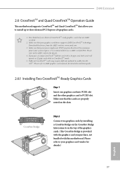
...5. CrossFire Bridge Step 2 Connect two graphics cards by installing a CrossFire Bridge on the CrossFire Bridge Interconnects on the slots. Z490 Extreme4 2.8 CrossFireXTM and Quad CrossFireXTM Operation Guide This motherboard supports CrossFireXTM and Quad CrossFireXTM that your power supply unit (PSU) can ... motherboard. Please refer to three identical PCI Express x16 graphics cards. 1. If you to install up to AMD graphics card manuals for details. 4. Please refer to the AMD's website for detailed installation guide. 2.8.1 Installing Two CrossFireXTM-Ready Graphics Cards Step...
...5. CrossFire Bridge Step 2 Connect two graphics cards by installing a CrossFire Bridge on the CrossFire Bridge Interconnects on the slots. Z490 Extreme4 2.8 CrossFireXTM and Quad CrossFireXTM Operation Guide This motherboard supports CrossFireXTM and Quad CrossFireXTM that your power supply unit (PSU) can ... motherboard. Please refer to three identical PCI Express x16 graphics cards. 1. If you to install up to AMD graphics card manuals for details. 4. Please refer to the AMD's website for detailed installation guide. 2.8.1 Installing Two CrossFireXTM-Ready Graphics Cards Step...

User Manual
Page 71
...WR for channel B2. RFR Delay (CH A) Configure RFR Delay for Channel B. ODT NOM (A1) Use this to change ODT (CH A2) Auto/Manual settings. IO-L Offset (CH B) Configure IO latency offset for channel B1. ODT WR (A2) Configure the memory on die termination resistors' WR for channel... to change ODT (CH B2) Auto/Manual settings. The default is [Auto]. ODT WR (B1) Configure the memory on die termination resistors' WR for channel B. ODT NOM (B2) Use this to change ODT (CH B1) Auto/Manual settings. The default is [Auto]. Z490 Extreme4 IO-L Offset (CH A) Configure IO ...
...WR for channel B2. RFR Delay (CH A) Configure RFR Delay for Channel B. ODT NOM (A1) Use this to change ODT (CH A2) Auto/Manual settings. IO-L Offset (CH B) Configure IO latency offset for channel B1. ODT WR (A2) Configure the memory on die termination resistors' WR for channel... to change ODT (CH B2) Auto/Manual settings. The default is [Auto]. ODT WR (B1) Configure the memory on die termination resistors' WR for channel B. ODT NOM (B2) Use this to change ODT (CH B1) Auto/Manual settings. The default is [Auto]. Z490 Extreme4 IO-L Offset (CH A) Configure IO ...
