User Manual
Page 7
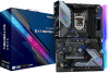
... will be subject to change without further notice. Chapter 4 contains the configuration guide of the software and utilities. ASRock website http://www.asrock.com. 1.1 Package Contents • ASRock Z490 Extreme4 Motherboard (ATX Form Factor) • ASRock Z490 Extreme4 Quick Installation Guide • ASRock Z490 Extreme4 Support CD • 4 x Serial ATA (SATA) Data Cables (Optional) • 4 x Screws for M.2 Sockets (Optional) • 2 x Standoffs for...
... will be subject to change without further notice. Chapter 4 contains the configuration guide of the software and utilities. ASRock website http://www.asrock.com. 1.1 Package Contents • ASRock Z490 Extreme4 Motherboard (ATX Form Factor) • ASRock Z490 Extreme4 Quick Installation Guide • ASRock Z490 Extreme4 Support CD • 4 x Serial ATA (SATA) Data Cables (Optional) • 4 x Screws for M.2 Sockets (Optional) • 2 x Standoffs for...

User Manual
Page 8
...8226; Supports ECC UDIMM memory modules (operate in VGA PCIe Slot (PCIE1) 2 dual at x16 (PCIE1); 1.2 Specifications Platform CPU • ATX Form Factor • 2oz Copper PCB • Supports 10th Gen and future generation Intel® CoreTM Processors (Socket 1200) • Digi...174; Turbo Boost 3.0 Technology • Supports Intel® K-Series unlocked CPUs • Supports ASRock BCLK Full-range Overclocking • Supports ASRock Hyper BCLK Engine III Chipset • Intel® Z490 Memory • Dual Channel DDR4 Memory Technology • 4 x DDR4 DIMM Slots • Supports...
...8226; Supports ECC UDIMM memory modules (operate in VGA PCIe Slot (PCIE1) 2 dual at x16 (PCIE1); 1.2 Specifications Platform CPU • ATX Form Factor • 2oz Copper PCB • Supports 10th Gen and future generation Intel® CoreTM Processors (Socket 1200) • Digi...174; Turbo Boost 3.0 Technology • Supports Intel® K-Series unlocked CPUs • Supports ASRock BCLK Full-range Overclocking • Supports ASRock Hyper BCLK Engine III Chipset • Intel® Z490 Memory • Dual Channel DDR4 Memory Technology • 4 x DDR4 DIMM Slots • Supports...
User Manual
Page 11
... Power Connec- tor) • 1 x Front Panel Audio Connector • 1 x Thunderbolt AIC Connector (5-pin) (Supports ASRock Thunderbolt 3 AIC R2.0 Card only) 5 English Z490 Extreme4 • 1 x Ultra M.2 Socket (M2_2), supports M Key type 2260/2280 M.2 SATA3 6.0 Gb/s module and M.2 ...module up to Gen3 x4 (32 Gb/s)** ** Supports Intel® OptaneTM Technology ** Supports NVMe SSD as boot disks ** Supports ASRock U.2 Kit Connector • 1 x SPI TPM Header • 1 x Power LED and Speaker Header • 2 x RGB...is in use. • 1 x 24 pin ATX Power Connector (Hi-Density Power Con-
... Power Connec- tor) • 1 x Front Panel Audio Connector • 1 x Thunderbolt AIC Connector (5-pin) (Supports ASRock Thunderbolt 3 AIC R2.0 Card only) 5 English Z490 Extreme4 • 1 x Ultra M.2 Socket (M2_2), supports M Key type 2260/2280 M.2 SATA3 6.0 Gb/s module and M.2 ...module up to Gen3 x4 (32 Gb/s)** ** Supports Intel® OptaneTM Technology ** Supports NVMe SSD as boot disks ** Supports ASRock U.2 Kit Connector • 1 x SPI TPM Header • 1 x Power LED and Speaker Header • 2 x RGB...is in use. • 1 x 24 pin ATX Power Connector (Hi-Density Power Con-

User Manual
Page 14
... Slots (DDR4_A1, DDR4_B1) 4 2 x 288-pin DDR4 DIMM Slots (DDR4_A2, DDR4_B2) 5 CPU/Water Pump Fan Connector (CPU_FAN2/WP_3A) 6 Addressable LED Header (ADDR_LED2) 7 RGB LED Header (RGB_LED2) 8 ATX Power Connector (ATXPWR1) 9 Front Panel Type C USB 3.2 Gen1 Header (USB31_TC_2) 10 USB 3.2 Gen1 Header (USB3_5_6) 11 SATA3 Connector (SATA3_2) 12 SATA3 Connector (SATA3_3) 13 SATA3...) 30 Addressable LED Header (ADDR_LED1) 31 Front Panel Audio Header (HD_AUDIO1) 32 Thunderbolt AIC Connector (TB1) 33 Chassis/Water Pump Fan Connector (CHA_FAN1/WP) 34 ATX 12V Power Connector (ATX12V2) 8 English No.
... Slots (DDR4_A1, DDR4_B1) 4 2 x 288-pin DDR4 DIMM Slots (DDR4_A2, DDR4_B2) 5 CPU/Water Pump Fan Connector (CPU_FAN2/WP_3A) 6 Addressable LED Header (ADDR_LED2) 7 RGB LED Header (RGB_LED2) 8 ATX Power Connector (ATXPWR1) 9 Front Panel Type C USB 3.2 Gen1 Header (USB31_TC_2) 10 USB 3.2 Gen1 Header (USB3_5_6) 11 SATA3 Connector (SATA3_2) 12 SATA3 Connector (SATA3_3) 13 SATA3...) 30 Addressable LED Header (ADDR_LED1) 31 Front Panel Audio Header (HD_AUDIO1) 32 Thunderbolt AIC Connector (TB1) 33 Chassis/Water Pump Fan Connector (CHA_FAN1/WP) 34 ATX 12V Power Connector (ATX12V2) 8 English No.
User Manual
Page 17
... to unplug the power cord before you handle the components. • Hold components by the edges and do so may damage the motherboard. 11 English Z490 Extreme4 Chapter 2 Installation This is an ATX form factor motherboard.
... to unplug the power cord before you handle the components. • Hold components by the edges and do so may damage the motherboard. 11 English Z490 Extreme4 Chapter 2 Installation This is an ATX form factor motherboard.

User Manual
Page 29
... cable to Pin 1-3. 12 24 1 13 This motherboard provides a 24-pin ATX power connector. FAN_SPEED_CONTROL CPU_FAN_SPEED FAN_VOLTAGE GND 1 2 34 This motherboard provides a 4-Pin water cooling CPU fan connector. Z490 Extreme4 CPU Fan Connector (4-pin CPU_FAN1) (see p.7, No. 2) CPU/Water Pump... Fan Connector (4-pin CPU_FAN2/ WP_3A) (see p.7, No. 5) ATX Power Connector (24-pin ATXPWR1) (see p.7, No. 8) ATX 12V Power Connector (8-pin ATX12V1) (see p.7, No...
... cable to Pin 1-3. 12 24 1 13 This motherboard provides a 24-pin ATX power connector. FAN_SPEED_CONTROL CPU_FAN_SPEED FAN_VOLTAGE GND 1 2 34 This motherboard provides a 4-Pin water cooling CPU fan connector. Z490 Extreme4 CPU Fan Connector (4-pin CPU_FAN1) (see p.7, No. 2) CPU/Water Pump... Fan Connector (4-pin CPU_FAN2/ WP_3A) (see p.7, No. 5) ATX Power Connector (24-pin ATXPWR1) (see p.7, No. 8) ATX 12V Power Connector (8-pin ATX12V1) (see p.7, No...

User Manual
Page 30
... to page 50 for further instructions on these two headers. otherwise, the cable may be damaged. *Please refer to choose from various LED lighting effects. ATX 12V Power Connector (4-pin ATX12V2) (see p.7, No. 34) Thunderbolt AIC Connectors (5-pin TB1) (see p.7, No. 32) SPI TPM Header (13-pin SPI_TPM_J1) (see p.7, No.... 17) RGB LED Headers (4-pin RGB_LED1) (see p.7, No. 29) (4-pin RGB_LED2) (see p.7, No. 7) Connecting an ATX 12V 4-pin cable here is optional. *The power supply plug fits into this connector in only one orientation.
... to page 50 for further instructions on these two headers. otherwise, the cable may be damaged. *Please refer to choose from various LED lighting effects. ATX 12V Power Connector (4-pin ATX12V2) (see p.7, No. 34) Thunderbolt AIC Connectors (5-pin TB1) (see p.7, No. 32) SPI TPM Header (13-pin SPI_TPM_J1) (see p.7, No.... 17) RGB LED Headers (4-pin RGB_LED1) (see p.7, No. 29) (4-pin RGB_LED2) (see p.7, No. 7) Connecting an ATX 12V 4-pin cable here is optional. *The power supply plug fits into this connector in only one orientation.