
User Manual
Page 4
...Installing the CPU 12 2.2 Installing the CPU Fan and Heatsink 15 2.3 Installing Memory Modules (DIMM) 16 2.4 Expansion Slots (PCI Express Slots) 18 2.5 Jumpers Setup 19 2.6 Onboard Headers and Connectors 20 2.7 CrossFireXTM and Quad CrossFireXTM... Operation Guide 24 2.7.1 Installing Two CrossFireXTM-Ready Graphics Cards 24 2.7.2 Driver Installation and Setup 26 2.8 M.2_SSD (NGFF) Module Installation Guide 27 Chapter 3 Software and Utilities Operation 32 3.1 Installing Drivers 32 3.2 A-Tuning 33 3.3 ASRock...
...Installing the CPU 12 2.2 Installing the CPU Fan and Heatsink 15 2.3 Installing Memory Modules (DIMM) 16 2.4 Expansion Slots (PCI Express Slots) 18 2.5 Jumpers Setup 19 2.6 Onboard Headers and Connectors 20 2.7 CrossFireXTM and Quad CrossFireXTM... Operation Guide 24 2.7.1 Installing Two CrossFireXTM-Ready Graphics Cards 24 2.7.2 Driver Installation and Setup 26 2.8 M.2_SSD (NGFF) Module Installation Guide 27 Chapter 3 Software and Utilities Operation 32 3.1 Installing Drivers 32 3.2 A-Tuning 33 3.3 ASRock...
User Manual
Page 10
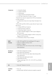
..., CE • ErP/EuP Ready (ErP/EuP ready power supply is required) 5 English Z370M Pro4 Connector • 1 x Print Port Header • 1 x COM Port Header • 1 x TPM Header • 1 x Chassis Intrusion and Speaker Header • 2 x CPU Fan Connectors (1 x 4-pin, 1 x 3-pin) * The CPU Fan Connector supports the CPU fan of maximum 1A (12W) fan power. • 2 x Chassis Fan Connectors (4-pin) (Smart Fan Speed Con-
..., CE • ErP/EuP Ready (ErP/EuP ready power supply is required) 5 English Z370M Pro4 Connector • 1 x Print Port Header • 1 x COM Port Header • 1 x TPM Header • 1 x Chassis Intrusion and Speaker Header • 2 x CPU Fan Connectors (1 x 4-pin, 1 x 3-pin) * The CPU Fan Connector supports the CPU fan of maximum 1A (12W) fan power. • 2 x Chassis Fan Connectors (4-pin) (Smart Fan Speed Con-

User Manual
Page 13
..., DDR4_B1) 3 2 x 288-pin DDR4 DIMM Slots (DDR4_A2, DDR4_B2) 4 CPU Fan Connector (CPU_FAN1) 5 CPU Fan Connector (CPU_FAN2) 6 Performance Mode / Easy OC Header (PM_EO) 7 ATX Power Connector (ATXPWR1) 8 USB 3.1 Gen1 Header (USB3_5_6) 9 SATA3 Connector (SATA3_0) 10 SATA3 Connector (SATA3_1) 11 Chassis Fan Connector (CHA_FAN2) 12 USB 3.1 Gen1 Header (USB3_7_8) 13 SATA3 Connector (SATA3_2) 14 SATA3 Connector (SATA3_3) 15...
..., DDR4_B1) 3 2 x 288-pin DDR4 DIMM Slots (DDR4_A2, DDR4_B2) 4 CPU Fan Connector (CPU_FAN1) 5 CPU Fan Connector (CPU_FAN2) 6 Performance Mode / Easy OC Header (PM_EO) 7 ATX Power Connector (ATXPWR1) 8 USB 3.1 Gen1 Header (USB3_5_6) 9 SATA3 Connector (SATA3_0) 10 SATA3 Connector (SATA3_1) 11 Chassis Fan Connector (CHA_FAN2) 12 USB 3.1 Gen1 Header (USB3_7_8) 13 SATA3 Connector (SATA3_2) 14 SATA3 Connector (SATA3_3) 15...

User Manual
Page 27
... plan to connect a FAN_SPEED FAN_VOLTAGE GND 3-Pin CPU fan, please connect it to the ground pin. C. E. CPU Fan Connectors (4-pin CPU_FAN1) (see p.7, No. 4) (3-... to OUT2_R and Audio_L (LIN) to MIC2_L. D. FAN_VOLTAGE_CONTROL GND FAN_SPEED_CONTROL vides two 4-Pin CPU fan (Quiet Fan) connectors. ATX Power Connector (24-pin ATXPWR1) (see p.7, No. 5) FAN_SPEED This motherboard...Pin 13. 1. MIC_RET and OUT_RET are for the AC'97 audio panel. Chassis Fan Connectors (4-pin CHA_FAN1) (see p.7, No. 26) (4-pin CHA_FAN2) (see p.7, No. 11) FAN_SPEED_CONTROL ...
... plan to connect a FAN_SPEED FAN_VOLTAGE GND 3-Pin CPU fan, please connect it to the ground pin. C. E. CPU Fan Connectors (4-pin CPU_FAN1) (see p.7, No. 4) (3-... to OUT2_R and Audio_L (LIN) to MIC2_L. D. FAN_VOLTAGE_CONTROL GND FAN_SPEED_CONTROL vides two 4-Pin CPU fan (Quiet Fan) connectors. ATX Power Connector (24-pin ATXPWR1) (see p.7, No. 5) FAN_SPEED This motherboard...Pin 13. 1. MIC_RET and OUT_RET are for the AC'97 audio panel. Chassis Fan Connectors (4-pin CHA_FAN1) (see p.7, No. 26) (4-pin CHA_FAN2) (see p.7, No. 11) FAN_SPEED_CONTROL ...


