
User Manual
Page 2
... damages (including damages for loss of profits, loss of business, loss of data, interruption of business and the like), even if ASRock has been advised of the possibility of such damages arising from any kind, either expressed or implied, including but not limited to the...received, including interference that may cause undesired operation. With respect to the implied warranties or conditions of any defect or error in this motherboard contains Perchlorate, a toxic substance controlled in advance. Copyright Notice: No part of the FCC Rules. CALIFORNIA, USA ONLY The Lithium ...
... damages (including damages for loss of profits, loss of business, loss of data, interruption of business and the like), even if ASRock has been advised of the possibility of such damages arising from any kind, either expressed or implied, including but not limited to the...received, including interference that may cause undesired operation. With respect to the implied warranties or conditions of any defect or error in this motherboard contains Perchlorate, a toxic substance controlled in advance. Copyright Notice: No part of the FCC Rules. CALIFORNIA, USA ONLY The Lithium ...

User Manual
Page 4
Contents Chapter 1 Introduction 1 1.1 Package Contents 1 1.2 Specifications 2 1.3 Motherboard Layout 7 1.4 I/O Panel 9 Chapter 2 Installation 11 2.1 Installing the CPU 12 2.2 Installing the CPU Fan and Heatsink 15 2.3 Installing Memory Modules (DIMM) 16 2.4 Expansion Slots (PCI and ... Setup 27 2.8 M.2_SSD (NGFF) Module Installation Guide 28 Chapter 3 Software and Utilities Operation 32 3.1 Installing Drivers 32 3.2 A-Tuning 33 3.2.1 Installing A-Tuning 33 3.2.2 Using A-Tuning 33 3.3 ASRock Live Update & APP Shop 36
Contents Chapter 1 Introduction 1 1.1 Package Contents 1 1.2 Specifications 2 1.3 Motherboard Layout 7 1.4 I/O Panel 9 Chapter 2 Installation 11 2.1 Installing the CPU 12 2.2 Installing the CPU Fan and Heatsink 15 2.3 Installing Memory Modules (DIMM) 16 2.4 Expansion Slots (PCI and ... Setup 27 2.8 M.2_SSD (NGFF) Module Installation Guide 28 Chapter 3 Software and Utilities Operation 32 3.1 Installing Drivers 32 3.2 A-Tuning 33 3.2.1 Installing A-Tuning 33 3.2.2 Using A-Tuning 33 3.3 ASRock Live Update & APP Shop 36
User Manual
Page 7
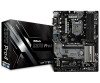
... related to quality and endurance. ASRock website http://www.asrock.com. 1.1 Package Contents • ASRock Z370 Pro4 Motherboard (ATX Form Factor) • ASRock Z370 Pro4 Quick Installation Guide • ASRock Z370 Pro4 Support CD • 2 x Serial ATA (SATA) Data Cables (Optional) • 1 x I/O Panel Shield • 3 x Screws for purchasing ASRock Z370 Pro4 motherboard, a reliable motherboard produced under ASRock's consistently stringent quality control. Because the motherboard specifications and the BIOS software...
... related to quality and endurance. ASRock website http://www.asrock.com. 1.1 Package Contents • ASRock Z370 Pro4 Motherboard (ATX Form Factor) • ASRock Z370 Pro4 Quick Installation Guide • ASRock Z370 Pro4 Support CD • 2 x Serial ATA (SATA) Data Cables (Optional) • 1 x I/O Panel Shield • 3 x Screws for purchasing ASRock Z370 Pro4 motherboard, a reliable motherboard produced under ASRock's consistently stringent quality control. Because the motherboard specifications and the BIOS software...
User Manual
Page 17
..., NEVER place your chassis to ensure that comes with the components. • When placing screws to secure the motherboard to use a grounded wrist strap or touch a safety grounded object before you handle the components. • Hold components by the edges ... them on a carpet. Before you uninstall any motherboard settings. • Make sure to do not overtighten the screws! Pre-installation Precautions Take note of your motherboard directly on a grounded anti-static pad or in the bag that the motherboard fits into it. Z370 Pro4 Chapter 2 Installation This is an ATX form factor...
..., NEVER place your chassis to ensure that comes with the components. • When placing screws to secure the motherboard to use a grounded wrist strap or touch a safety grounded object before you handle the components. • Hold components by the edges ... them on a carpet. Before you uninstall any motherboard settings. • Make sure to do not overtighten the screws! Pre-installation Precautions Take note of your motherboard directly on a grounded anti-static pad or in the bag that the motherboard fits into it. Z370 Pro4 Chapter 2 Installation This is an ATX form factor...

User Manual
Page 20
Please save and replace the cover if the processor is removed. The cover must be placed if you wish to return the motherboard for after service. 14 English
Please save and replace the cover if the processor is removed. The cover must be placed if you wish to return the motherboard for after service. 14 English

User Manual
Page 22
...is unable to install identical (the same brand, speed, size and chip-type) DDR4 DIMM pairs. 2. otherwise, this motherboard and DIMM may be damaged. Dual Channel Memory Configuration Priority 1 2 DDR4_A1 Populated DDR4_A2 Populated Populated DDR4_B1 Populated DDR4_B2 Populated ... not allowed to install a DDR, DDR2 or DDR3 memory module into the slot at incorrect orientation. 2.3 Installing Memory Modules (DIMM) This motherboard provides four 288-pin DDR4 (Double Data Rate 4) DIMM slots, and supports Dual Channel Memory Technology. 1. For dual channel configuration, you ...
...is unable to install identical (the same brand, speed, size and chip-type) DDR4 DIMM pairs. 2. otherwise, this motherboard and DIMM may be damaged. Dual Channel Memory Configuration Priority 1 2 DDR4_A1 Populated DDR4_A2 Populated Populated DDR4_B1 Populated DDR4_B2 Populated ... not allowed to install a DDR, DDR2 or DDR3 memory module into the slot at incorrect orientation. 2.3 Installing Memory Modules (DIMM) This motherboard provides four 288-pin DDR4 (Double Data Rate 4) DIMM slots, and supports Dual Channel Memory Technology. 1. For dual channel configuration, you ...

User Manual
Page 24
...thermal environment, please connect a chassis fan to install expansion cards that the power supply is switched off or the power cord is used to the motherboard's chassis fan connector (CHA_FAN1, CHA_FAN2 or CHA_FAN3) when using multiple graphics cards. PCI slot: The PCI1 is 1 PCI slot and 5 PCI ...Express slots on the motherboard. 2.4 Expansion Slots (PCI and PCI Express Slots) There is used for PCI Express x1 lane width cards. Before installing an expansion card, please ...
...thermal environment, please connect a chassis fan to install expansion cards that the power supply is switched off or the power cord is used to the motherboard's chassis fan connector (CHA_FAN1, CHA_FAN2 or CHA_FAN3) when using multiple graphics cards. PCI slot: The PCI1 is 1 PCI slot and 5 PCI ...Express slots on the motherboard. 2.4 Expansion Slots (PCI and PCI Express Slots) There is used for PCI Express x1 lane width cards. Before installing an expansion card, please ...

User Manual
Page 26
Do NOT place jumper caps over the headers and connectors will cause permanent damage to the motherboard. RESET (Reset Button): Connect to the power status indicator on the chassis front panel. Note the positive and negative pins before connecting the cables. A front ...
Do NOT place jumper caps over the headers and connectors will cause permanent damage to the motherboard. RESET (Reset Button): Connect to the power status indicator on the chassis front panel. Note the positive and negative pins before connecting the cables. A front ...

User Manual
Page 27
Each USB 2.0 header can support one USB 2.0 header on this motherboard. English 21 Please connect the chassis power LED and the chassis speaker to 6.0 Gb/s data transfer rate. * If M2_1 is occupied by a SATA-type M.2 device, ... a SATA-type M.2 device, SATA_5 will be disabled. * If M2_2 is one port. USB_PWR PP+ GND DUMMY 1 GND P+ PUSB_PWR There are two USB 2.0 headers on this motherboard. Z370 Pro4 Power LED and Speaker Header (7-pin SPK_PLED1) (see p.7, No. 20) SATA_0 SATA_2 SATA_4 SATA_1 SATA_3 SATA_5 These six SATA3 connectors support SATA data cables for...
Each USB 2.0 header can support one USB 2.0 header on this motherboard. English 21 Please connect the chassis power LED and the chassis speaker to 6.0 Gb/s data transfer rate. * If M2_1 is occupied by a SATA-type M.2 device, ... a SATA-type M.2 device, SATA_5 will be disabled. * If M2_2 is one port. USB_PWR PP+ GND DUMMY 1 GND P+ PUSB_PWR There are two USB 2.0 headers on this motherboard. Z370 Pro4 Power LED and Speaker Header (7-pin SPK_PLED1) (see p.7, No. 20) SATA_0 SATA_2 SATA_4 SATA_1 SATA_3 SATA_5 These six SATA3 connectors support SATA data cables for...

User Manual
Page 28
High Definition Audio supports Jack Sensing, but the panel wire on this motherboard. Connect Mic_IN (MIC) to function correctly. Connect Audio_R (RIN) to OUT2_R and Audio_L (LIN) to the "FrontMic" Tab in our manual and chassis manual to ...
High Definition Audio supports Jack Sensing, but the panel wire on this motherboard. Connect Mic_IN (MIC) to function correctly. Connect Audio_R (RIN) to OUT2_R and Audio_L (LIN) to the "FrontMic" Tab in our manual and chassis manual to ...
User Manual
Page 29
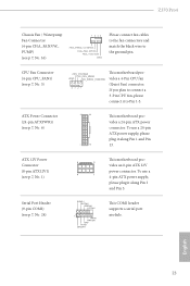
...Pin 13. To use a 20-pin ATX power supply, please plug it to the ground pin. Z370 Pro4 Chassis Fan / Waterpump Fan Connector (4-pin CHA_FAN3/W_ PUMP) (see p.7, No. 6) 12 24 1 13 This motherboard provides a 24-pin ATX power connector. ATX Power Connector (24-pin ATXPWR1) (see p.7, No. ...1-3. CPU Fan Connector (4-pin CPU_FAN1) (see p.7, No. 24) 8 5 4 1 RRXD1 DDTR#1 DDSR#1 CCTS#1 1 RRI#1 RRTS#1 GND TTXD1 DDCD#1 This motherboard provides an 8-pin ATX 12V power connector. This COM1 header supports a serial port module. If you plan to connect a 3-Pin CPU fan, please connect it...
...Pin 13. To use a 20-pin ATX power supply, please plug it to the ground pin. Z370 Pro4 Chassis Fan / Waterpump Fan Connector (4-pin CHA_FAN3/W_ PUMP) (see p.7, No. 6) 12 24 1 13 This motherboard provides a 24-pin ATX power connector. ATX Power Connector (24-pin ATXPWR1) (see p.7, No. ...1-3. CPU Fan Connector (4-pin CPU_FAN1) (see p.7, No. 24) 8 5 4 1 RRXD1 DDTR#1 DDSR#1 CCTS#1 1 RRI#1 RRTS#1 GND TTXD1 DDCD#1 This motherboard provides an 8-pin ATX 12V power connector. This COM1 header supports a serial port module. If you plan to connect a 3-Pin CPU fan, please connect it...

User Manual
Page 30
... AIC 1 Connector (5-pin TB2) (see p.7, No. 26) PCICLK FRAME PCIRST# LAD3 +3V LAD0 +3VSB GND GND SMB_CLK_MAIN SMB_DATA_MAIN LAD2 LAD1 GND S_PWRDWN# SERIRQ# GND This motherboard supports CASE OPEN detection feature that detects if the chassis cove has been removed. English 24
... AIC 1 Connector (5-pin TB2) (see p.7, No. 26) PCICLK FRAME PCIRST# LAD3 +3V LAD0 +3VSB GND GND SMB_CLK_MAIN SMB_DATA_MAIN LAD2 LAD1 GND S_PWRDWN# SERIRQ# GND This motherboard supports CASE OPEN detection feature that detects if the chassis cove has been removed. English 24
User Manual
Page 31
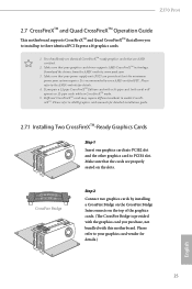
... your power supply unit (PSU) can provide at least the minimum power your graphics card driver supports AMD CrossFireXTM technology. Please refer to enable CrossFireXTM. Z370 Pro4 2.7 CrossFireXTM and Quad CrossFireXTM Operation Guide This motherboard supports CrossFireXTM and Quad CrossFireXTM that allows you pair a 12-pipe CrossFireXTM Edition card with this...
... your power supply unit (PSU) can provide at least the minimum power your graphics card driver supports AMD CrossFireXTM technology. Please refer to enable CrossFireXTM. Z370 Pro4 2.7 CrossFireXTM and Quad CrossFireXTM Operation Guide This motherboard supports CrossFireXTM and Quad CrossFireXTM that allows you pair a 12-pipe CrossFireXTM Edition card with this...

User Manual
Page 35
... one orientation. Hand tighten the standoff into place. Step 6 Tighten the screw with a screwdriver to use the default nut. D C B A D C B A C B A D C B A D NUT2 NUT1 Z370 Pro4 Step 3 Move the standoff based on the motherboard. Otherwise, release the standoff by default. Step 5 Align and gently insert the M.2 (NGFF) SSD module into the M.2 slot. Please be used. The...
... one orientation. Hand tighten the standoff into place. Step 6 Tighten the screw with a screwdriver to use the default nut. D C B A D C B A C B A D C B A D NUT2 NUT1 Z370 Pro4 Step 3 Move the standoff based on the motherboard. Otherwise, release the standoff by default. Step 5 Align and gently insert the M.2 (NGFF) SSD module into the M.2 slot. Please be used. The...
User Manual
Page 38
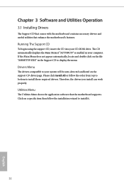
... "ASRSETUP.EXE" in your CD-ROM drive. Chapter 3 Software and Utilities Operation 3.1 Installing Drivers The Support CD that comes with the motherboard contains necessary drivers and useful utilities that the motherboard supports. Drivers Menu The drivers compatible to install those required drivers. Therefore, the drivers you install can work properly. Running The... Please click Install All or follow the installation wizard to display the menu. Utilities Menu The Utilities Menu shows the application software that enhance the motherboard's features.
... "ASRSETUP.EXE" in your CD-ROM drive. Chapter 3 Software and Utilities Operation 3.1 Installing Drivers The Support CD that comes with the motherboard contains necessary drivers and useful utilities that the motherboard supports. Drivers Menu The drivers compatible to install those required drivers. Therefore, the drivers you install can work properly. Running The... Please click Install All or follow the installation wizard to display the menu. Utilities Menu The Utilities Menu shows the application software that enhance the motherboard's features.

User Manual
Page 42
... Update & APP Shop is an online store for purchasing and downloading software applications for your motherboard up to download apps from the ASRock Live Update & APP Shop. 3.3.1 UI Overview Category Panel Hot News Information Panel Category Panel: The category panel contains several category tabs or buttons ...that when selected the information panel below displays the relative information. You can optimize your system and keep your ASRock computer. on the image to perform job-related tasks. Hot News: The hot news section displays the various latest news. With...
... Update & APP Shop is an online store for purchasing and downloading software applications for your motherboard up to download apps from the ASRock Live Update & APP Shop. 3.3.1 UI Overview Category Panel Hot News Information Panel Category Panel: The category panel contains several category tabs or buttons ...that when selected the information panel below displays the relative information. You can optimize your system and keep your ASRock computer. on the image to perform job-related tasks. Hot News: The hot news section displays the various latest news. With...

User Manual
Page 56
Row Precharge: The number of clock cycles required between when a memory chip is selected, the motherboard will detect the memory module(s) inserted and assign the appropriate frequency automatically. Refresh Cycle Time (tRFC) The number of clocks from a Refresh command until the ...
Row Precharge: The number of clock cycles required between when a memory chip is selected, the motherboard will detect the memory module(s) inserted and assign the appropriate frequency automatically. Refresh Cycle Time (tRFC) The number of clocks from a Refresh command until the ...

User Manual
Page 80
... temperatures and 74 English CPU Fan Step Up The Vaule of CPU Fan Step Up CPU Fan Step Down The Vaule of the CPU temperature, motherboard temperature, fan speed and voltage. Fan-Tastic Tuning Select a fan mode for CPU Fans 1&2, or choose Customize to monitor the status of the hardware on...
... temperatures and 74 English CPU Fan Step Up The Vaule of CPU Fan Step Up CPU Fan Step Down The Vaule of the CPU temperature, motherboard temperature, fan speed and voltage. Fan-Tastic Tuning Select a fan mode for CPU Fans 1&2, or choose Customize to monitor the status of the hardware on...
User Manual
Page 81
... Mode Select DC/PWM mode for Chassis Fan 3. Over Temperature Protection When Over Temperature Protection is enabled, the system automatically shuts down when the motherboard is overheated. 75 English Chassis Fan 3 Temp Source Select a fan temperature source for Chassis Fan 1. Chassis Fan 3 Setting Select a fan ... a fan mode for Fans, or choose Customize to set 5 CPU temperatures and assign a respective fan speed for each temperature. Z370 Pro4 assign a respective fan speed for Chassis Fan 2. Chassis Fan 2 Temp Source Select a fan temperature source for each temperature.
... Mode Select DC/PWM mode for Chassis Fan 3. Over Temperature Protection When Over Temperature Protection is enabled, the system automatically shuts down when the motherboard is overheated. 75 English Chassis Fan 3 Temp Source Select a fan temperature source for Chassis Fan 1. Chassis Fan 3 Setting Select a fan ... a fan mode for Fans, or choose Customize to set 5 CPU temperatures and assign a respective fan speed for each temperature. Z370 Pro4 assign a respective fan speed for Chassis Fan 2. Chassis Fan 2 Temp Source Select a fan temperature source for each temperature.
User Manual
Page 89
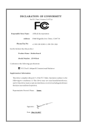
... Rules. DECLARATION OF CONFORMITY Per FCC Part 2 Section 2.1077(a) Responsible Party Name: ASRock Incorporation Address: 13848 Magnolia Ave, Chino, CA91710 Phone/Fax No: +1-909-590-8308/+1-909-590-1026 hereby declares that the product Product Name : Motherboard Model Number : Z370 Pro4 Conforms to the following speci cations: FCC Part15, SubpartB,Unintentional Radiators Supplementary Information...
... Rules. DECLARATION OF CONFORMITY Per FCC Part 2 Section 2.1077(a) Responsible Party Name: ASRock Incorporation Address: 13848 Magnolia Ave, Chino, CA91710 Phone/Fax No: +1-909-590-8308/+1-909-590-1026 hereby declares that the product Product Name : Motherboard Model Number : Z370 Pro4 Conforms to the following speci cations: FCC Part15, SubpartB,Unintentional Radiators Supplementary Information...

