
User Manual
Page 2
... by the purchaser for loss of profits, loss of business, loss of data, interruption of business and the like), even if ASRock has been advised of the possibility of this motherboard contains Perchlorate, a toxic substance controlled in this device must accept any kind, either expressed or implied, including but not limited to...
... by the purchaser for loss of profits, loss of business, loss of data, interruption of business and the like), even if ASRock has been advised of the possibility of this motherboard contains Perchlorate, a toxic substance controlled in this device must accept any kind, either expressed or implied, including but not limited to...
User Manual
Page 5
Contents Chapter 1 Introduction 1 1.1 Package Contents 1 1.2 Specifications 2 1.3 Motherboard Layout 7 1.4 I/O Panel 10 1.5 WiFi-802.11ac Module and ASRock WiFi 2.4/5 GHz Antennas (for Z370 Killer SLI/ac only) 13 Chapter 2 Installation 15 2.1 Installing the CPU 16 2.2 Installing the CPU Fan and Heatsink 19 2.3 Installing Memory Modules (DIMM) 20 2.4 Expansion Slots (PCI Express ...
Contents Chapter 1 Introduction 1 1.1 Package Contents 1 1.2 Specifications 2 1.3 Motherboard Layout 7 1.4 I/O Panel 10 1.5 WiFi-802.11ac Module and ASRock WiFi 2.4/5 GHz Antennas (for Z370 Killer SLI/ac only) 13 Chapter 2 Installation 15 2.1 Installing the CPU 16 2.2 Installing the CPU Fan and Heatsink 19 2.3 Installing Memory Modules (DIMM) 20 2.4 Expansion Slots (PCI Express ...
User Manual
Page 8
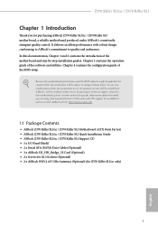
... • ASRock Z370 Killer SLI/ac / Z370 Killer SLI Motherboard (ATX Form Factor) • ASRock Z370 Killer SLI/ac / Z370 Killer SLI Quick Installation Guide • ASRock Z370 Killer SLI/ac / Z370 Killer SLI Support CD • 1 x I/O Panel Shield • 2 x Serial ATA (SATA) Data Cables (Optional) • 1 x ASRock SLI_HB_Bridge_2S Card (Optional) • 2 x Screws for M.2 Sockets (Optional) • 2 x ASRock WiFi 2.4/5 GHz Antennas (Optional) (for purchasing ASRock Z370 Killer SLI/ac / Z370 Killer SLI motherboard, a reliable motherboard produced under ASRock's consistently stringent...
... • ASRock Z370 Killer SLI/ac / Z370 Killer SLI Motherboard (ATX Form Factor) • ASRock Z370 Killer SLI/ac / Z370 Killer SLI Quick Installation Guide • ASRock Z370 Killer SLI/ac / Z370 Killer SLI Support CD • 1 x I/O Panel Shield • 2 x Serial ATA (SATA) Data Cables (Optional) • 1 x ASRock SLI_HB_Bridge_2S Card (Optional) • 2 x Screws for M.2 Sockets (Optional) • 2 x ASRock WiFi 2.4/5 GHz Antennas (Optional) (for purchasing ASRock Z370 Killer SLI/ac / Z370 Killer SLI motherboard, a reliable motherboard produced under ASRock's consistently stringent...
User Manual
Page 14
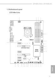
1.3 Motherboard Layout Z370 Killer SLI/ac Z370 Killer SLI/ac / Z370 Killer SLI PS2 Keyboard /Mouse USB 3.1 Gen1 T: USB1 B: USB2 HDMI1 M2_WIFI1 ATX12V1 CPU_FAN1 DDR4_A1 (64 bit, 288-pin module) DDR4_A2 (64 bit, 288-pin...: Central/Bass LINE IN Center: REAR SPK Bottom: Optical SPDIF Top: Center: FRONT Bottom: MIC IN USB3_5_6 CHA_FAN2 1 PCIE1 M2_1 USB3_TC_2 SATA_4_5 SATA_2_3 PCIE2 Z370 Killer SLI/ac PCIE3 Intel Z370 SATA_0_1 HD_AUDIO1 1 PCIE4 T B2 1 PCIE5 PCIE6 COM1 1 TPMS1 1 CMOS Battery RoHS CLRMOS1 1 RGB_LED1 1 CI1 1 PM_EO 1 USB_3_4 USB_1_2 1 1 Ultra M.2 PCIe ...
1.3 Motherboard Layout Z370 Killer SLI/ac Z370 Killer SLI/ac / Z370 Killer SLI PS2 Keyboard /Mouse USB 3.1 Gen1 T: USB1 B: USB2 HDMI1 M2_WIFI1 ATX12V1 CPU_FAN1 DDR4_A1 (64 bit, 288-pin module) DDR4_A2 (64 bit, 288-pin...: Central/Bass LINE IN Center: REAR SPK Bottom: Optical SPDIF Top: Center: FRONT Bottom: MIC IN USB3_5_6 CHA_FAN2 1 PCIE1 M2_1 USB3_TC_2 SATA_4_5 SATA_2_3 PCIE2 Z370 Killer SLI/ac PCIE3 Intel Z370 SATA_0_1 HD_AUDIO1 1 PCIE4 T B2 1 PCIE5 PCIE6 COM1 1 TPMS1 1 CMOS Battery RoHS CLRMOS1 1 RGB_LED1 1 CI1 1 PM_EO 1 USB_3_4 USB_1_2 1 1 Ultra M.2 PCIe ...
User Manual
Page 20
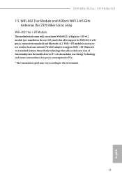
... Technology and ensures extraordinary low power consumption for WiFi 802.11 a/b/ g/n/ac connectivity standards and Bluetooth v4.2. Z370 Killer SLI/ac / Z370 Killer SLI 1.5 WiFi-802.11ac Module and ASRock WiFi 2.4/5 GHz Antennas (for Z370 Killer SLI/ac only) WiFi-802.11ac + BT Module This motherboard comes with an exclusive WiFi 802.11 a/b/g/n/ac + BT v4.2 module (pre-installed on the rear I/O panel) that adds...
... Technology and ensures extraordinary low power consumption for WiFi 802.11 a/b/ g/n/ac connectivity standards and Bluetooth v4.2. Z370 Killer SLI/ac / Z370 Killer SLI 1.5 WiFi-802.11ac Module and ASRock WiFi 2.4/5 GHz Antennas (for Z370 Killer SLI/ac only) WiFi-802.11ac + BT Module This motherboard comes with an exclusive WiFi 802.11 a/b/g/n/ac + BT v4.2 module (pre-installed on the rear I/O panel) that adds...

User Manual
Page 22
... ICs. • Whenever you uninstall any components, place them on a carpet. Z370 Killer SLI/ac / Z370 Killer SLI Chapter 2 Installation This is an ATX form factor motherboard. Failure to the chassis, please do so may damage the motherboard. 15 English Pre-installation Precautions Take note of your motherboard directly on a grounded anti-static pad or in the bag that the...
... ICs. • Whenever you uninstall any components, place them on a carpet. Z370 Killer SLI/ac / Z370 Killer SLI Chapter 2 Installation This is an ATX form factor motherboard. Failure to the chassis, please do so may damage the motherboard. 15 English Pre-installation Precautions Take note of your motherboard directly on a grounded anti-static pad or in the bag that the...

User Manual
Page 25
Please save and replace the cover if the processor is removed. The cover must be placed if you wish to return the motherboard for after service. 18 English
Please save and replace the cover if the processor is removed. The cover must be placed if you wish to return the motherboard for after service. 18 English

User Manual
Page 27
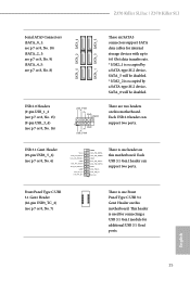
.... It is unable to install identical (the same brand, speed, size and chip-type) DDR4 DIMM pairs. 2. It is not allowed to the motherboard and the DIMM if you always need to activate Dual Channel Memory Technology with only one correct orientation. otherwise, this... motherboard and DIMM may be damaged. English 20 Dual Channel Memory Configuration Priority 1 2 DDR4_A1 Populated DDR4_A2 Populated Populated DDR4_B1 Populated DDR4_B2 Populated Populated The...
.... It is unable to install identical (the same brand, speed, size and chip-type) DDR4 DIMM pairs. 2. It is not allowed to the motherboard and the DIMM if you always need to activate Dual Channel Memory Technology with only one correct orientation. otherwise, this... motherboard and DIMM may be damaged. English 20 Dual Channel Memory Configuration Priority 1 2 DDR4_A1 Populated DDR4_A2 Populated Populated DDR4_B1 Populated DDR4_B2 Populated Populated The...

User Manual
Page 29
...is used for PCI Express x16 lane width graphics cards. 2.4 Expansion Slots (PCI Express Slots) There are 6 PCI Express slots on the motherboard. English 22 PCIE4 (PCIe 3.0 x16 slot) is used for PCI Express x1 lane width cards. Please read the documentation of the expansion ... PCIE4 N/A Two Graphics Cards in CrossFireXTM or SLITM x8 x8 Mode For a better thermal environment, please connect a chassis fan to the motherboard's chassis fan connector (CHA_FAN1, CHA_FAN2 or CHA_FAN3 ) when using multiple graphics cards. Before installing an expansion card, please make necessary hardware ...
...is used for PCI Express x16 lane width graphics cards. 2.4 Expansion Slots (PCI Express Slots) There are 6 PCI Express slots on the motherboard. English 22 PCIE4 (PCIe 3.0 x16 slot) is used for PCI Express x1 lane width cards. Please read the documentation of the expansion ... PCIE4 N/A Two Graphics Cards in CrossFireXTM or SLITM x8 x8 Mode For a better thermal environment, please connect a chassis fan to the motherboard's chassis fan connector (CHA_FAN1, CHA_FAN2 or CHA_FAN3 ) when using multiple graphics cards. Before installing an expansion card, please make necessary hardware ...

User Manual
Page 31
... hard drive is operating. Note the positive and negative pins before connecting the cables. You may differ by chassis. RESET (Reset Switch): Connect to the motherboard. PLED (System Power LED): Connect to the hard drive activity LED on the chassis front panel. When connecting your system using the power switch. The...
... hard drive is operating. Note the positive and negative pins before connecting the cables. You may differ by chassis. RESET (Reset Switch): Connect to the motherboard. PLED (System Power LED): Connect to the hard drive activity LED on the chassis front panel. When connecting your system using the power switch. The...
User Manual
Page 32
...) (see p.7 or 8, No. 7) There is one Front Panel Type C USB 3.1 Gen1 Header on this motherboard. Each USB 2.0 header can support two ports. Each USB 3.1 Gen1 header can support two ports. English 25 USB_PWR... GND IntA_PA_DIntA_PA_D+ Vbus IntA_PB_SSRXIntA_PB_SSRX+ GND IntA_PB_SSTXIntA_PB_SSTX+ GND IntA_PB_DIntA_PB_D+ Dummy 1 There is one header on this motherboard. This header is occupied by a SATA-type M.2 device, SATA_5 will be disabled. Z370 Killer SLI/ac / Z370 Killer SLI Serial ATA3 Connectors (SATA_0_1: see p.7 or 8, No. 10) (SATA_2_3: see p.7 or 8, No...
...) (see p.7 or 8, No. 7) There is one Front Panel Type C USB 3.1 Gen1 Header on this motherboard. Each USB 2.0 header can support two ports. Each USB 3.1 Gen1 header can support two ports. English 25 USB_PWR... GND IntA_PA_DIntA_PA_D+ Vbus IntA_PB_SSRXIntA_PB_SSRX+ GND IntA_PB_SSTXIntA_PB_SSTX+ GND IntA_PB_DIntA_PB_D+ Dummy 1 There is one header on this motherboard. This header is occupied by a SATA-type M.2 device, SATA_5 will be disabled. Z370 Killer SLI/ac / Z370 Killer SLI Serial ATA3 Connectors (SATA_0_1: see p.7 or 8, No. 10) (SATA_2_3: see p.7 or 8, No...

User Manual
Page 33
...Connect Mic_IN (MIC) to install your system. 2. Connect Ground (GND) to Pin 1-3. E. D. If you use an AC'97 audio panel, please install it to Ground (GND). If you plan to connect a 3-Pin chassis water cooler fan... and OUT_RET are for the HD audio panel only. To activate the front mic, go to connect them for the AC'97 audio panel. Connect Audio_R (RIN) to OUT2_R and Audio_L (LIN) to the front audio panel. 1. Front ... PUMP) (see p.7 or 8, No. 13) 4 3 2 1 FAN_SPEED_CONTROL CHA_FAN_SPEED FAN_VOLTAGE GND This motherboard provides a 4-Pin water cooling chassis fan connector.
...Connect Mic_IN (MIC) to install your system. 2. Connect Ground (GND) to Pin 1-3. E. D. If you use an AC'97 audio panel, please install it to Ground (GND). If you plan to connect a 3-Pin chassis water cooler fan... and OUT_RET are for the HD audio panel only. To activate the front mic, go to connect them for the AC'97 audio panel. Connect Audio_R (RIN) to OUT2_R and Audio_L (LIN) to the front audio panel. 1. Front ... PUMP) (see p.7 or 8, No. 13) 4 3 2 1 FAN_SPEED_CONTROL CHA_FAN_SPEED FAN_VOLTAGE GND This motherboard provides a 4-Pin water cooling chassis fan connector.
User Manual
Page 34
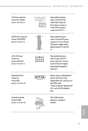
... a 4 1 4-pin ATX power supply, please plug it along Pin 1 and Pin 13. 8 5 This motherboard pro- vides a 8-pin ATX 12V power connector. To use a 20-pin ATX power supply, please plug it to PCIE4 (default slot). English 27 Z370 Killer SLI/ac / Z370 Killer SLI CPU Fan Connector (4-pin CPU_FAN1) (see p.7 or 8, No. 4) ATX Power Connector (24-pin ATXPWR1...
... a 4 1 4-pin ATX power supply, please plug it along Pin 1 and Pin 13. 8 5 This motherboard pro- vides a 8-pin ATX 12V power connector. To use a 20-pin ATX power supply, please plug it to PCIE4 (default slot). English 27 Z370 Killer SLI/ac / Z370 Killer SLI CPU Fan Connector (4-pin CPU_FAN1) (see p.7 or 8, No. 4) ATX Power Connector (24-pin ATXPWR1...

User Manual
Page 35
... RGB LED cable in the wrong orientation; PCICLK FRAME PCIRST# LAD3 +3V LAD0 +3VSB GND GND SMB_CLK_MAIN SMB_DATA_MAIN LAD2 LAD1 GND S_PWRDWN# SERIRQ# GND This motherboard supports CASE OPEN detection feature that detects if the chassis cove has been removed. RGB LED header is used to choose from various LED lighting...
... RGB LED cable in the wrong orientation; PCICLK FRAME PCIRST# LAD3 +3V LAD0 +3VSB GND GND SMB_CLK_MAIN SMB_DATA_MAIN LAD2 LAD1 GND S_PWRDWN# SERIRQ# GND This motherboard supports CASE OPEN detection feature that detects if the chassis cove has been removed. RGB LED header is used to choose from various LED lighting...
User Manual
Page 36
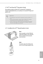
... recommended to PCIE4 slot. Step 2 If required, connect the auxiliary power source to two identical PCI Express x16 graphics cards. Requirements 1. Z370 Killer SLI/ac / Z370 Killer SLI 2.7 SLITM and Quad SLITM Operation Guide This motherboard supports NVIDIA® SLITM and Quad SLITM (Scalable Link Interface) technology that allows you to install up to the PCI Express graphics...
... recommended to PCIE4 slot. Step 2 If required, connect the auxiliary power source to two identical PCI Express x16 graphics cards. Requirements 1. Z370 Killer SLI/ac / Z370 Killer SLI 2.7 SLITM and Quad SLITM Operation Guide This motherboard supports NVIDIA® SLITM and Quad SLITM (Scalable Link Interface) technology that allows you to install up to the PCI Express graphics...
User Manual
Page 39
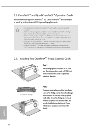
...AMD certified. 2. Please refer to three identical PCI Express x16 graphics cards. 1. 2.8 CrossFireXTM and Quad CrossFireXTM Operation Guide This motherboard supports CrossFireXTM and Quad CrossFireXTM that allows you to install up to your graphics card vendor for details.) English 32 You should ... CrossFireXTM. Please refer to AMD graphics card manuals for details. 4. If you pair a 12-pipe CrossFireXTM Edition card with this motherboard. CrossFire Bridge Step 2 Connect two graphics cards by installing a CrossFire Bridge on the CrossFire Bridge Interconnects on the slots. Download...
...AMD certified. 2. Please refer to three identical PCI Express x16 graphics cards. 1. 2.8 CrossFireXTM and Quad CrossFireXTM Operation Guide This motherboard supports CrossFireXTM and Quad CrossFireXTM that allows you to install up to your graphics card vendor for details.) English 32 You should ... CrossFireXTM. Please refer to AMD graphics card manuals for details. 4. If you pair a 12-pipe CrossFireXTM Edition card with this motherboard. CrossFire Bridge Step 2 Connect two graphics cards by installing a CrossFire Bridge on the CrossFire Bridge Interconnects on the slots. Download...

User Manual
Page 43
... you are going to use the default nut. Step 6 Tighten the screw with a screwdriver to secure the module into the desired nut location on the motherboard. E D C B A E D C B A C B A E D C B A E D NUT2 NUT1 Step 3 Move the standoff based on the nut to be aware that the M.2 (NGFF) SSD module only fits in one orientation. Please do...
... you are going to use the default nut. Step 6 Tighten the screw with a screwdriver to secure the module into the desired nut location on the motherboard. E D C B A E D C B A C B A E D C B A E D NUT2 NUT1 Step 3 Move the standoff based on the nut to be aware that the M.2 (NGFF) SSD module only fits in one orientation. Please do...
User Manual
Page 46
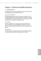
... in the Support CD to your computer. Z370 Killer SLI/ac / Z370 Killer SLI Chapter 3 Software and Utilities Operation 3.1 Installing Drivers The Support CD that comes with the motherboard contains necessary drivers and useful utilities that the motherboard supports. Utilities Menu The Utilities Menu shows... the application software that enhance the motherboard's features. Running The Support CD To begin using...
... in the Support CD to your computer. Z370 Killer SLI/ac / Z370 Killer SLI Chapter 3 Software and Utilities Operation 3.1 Installing Drivers The Support CD that comes with the motherboard contains necessary drivers and useful utilities that the motherboard supports. Utilities Menu The Utilities Menu shows... the application software that enhance the motherboard's features. Running The Support CD To begin using...
User Manual
Page 50
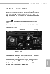
...The information panel in the center displays data about the currently selected category and allows users to date simply with a few clicks. Z370 Killer SLI/ac / Z370 Killer SLI 3.3 ASRock Live Update & APP Shop The ASRock Live Update & APP Shop is an online store for purchasing and downloading software applications for your desktop to access... panel below displays the relative information. Hot News: The hot news section displays the various latest news. Click on your ASRock computer. You can optimize your system and keep your motherboard up to perform job-related tasks.
...The information panel in the center displays data about the currently selected category and allows users to date simply with a few clicks. Z370 Killer SLI/ac / Z370 Killer SLI 3.3 ASRock Live Update & APP Shop The ASRock Live Update & APP Shop is an online store for purchasing and downloading software applications for your desktop to access... panel below displays the relative information. Hot News: The hot news section displays the various latest news. Click on your ASRock computer. You can optimize your system and keep your motherboard up to perform job-related tasks.
User Manual
Page 56
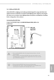
... do so may be damaged. 2. RGB_LED 1 12V G R B 1 B R 12V G 1. Failure to do not come with the package. 2. Z370 Killer SLI/ac / Z370 Killer SLI 3.4 ASRock RGB LED ASRock RGB LED is a lighting control utility specifically designed for unique individuals with sophisticated tastes to motherboard components. 1. Never install the RGB LED cable in the wrong orientation; otherwise, the cable may cause damages...
... do so may be damaged. 2. RGB_LED 1 12V G R B 1 B R 12V G 1. Failure to do not come with the package. 2. Z370 Killer SLI/ac / Z370 Killer SLI 3.4 ASRock RGB LED ASRock RGB LED is a lighting control utility specifically designed for unique individuals with sophisticated tastes to motherboard components. 1. Never install the RGB LED cable in the wrong orientation; otherwise, the cable may cause damages...

