User Manual
Page 5
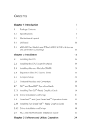
...Package Contents 1 1.2 Specifications 2 1.3 Motherboard Layout 7 1.4 I/O Panel 10 1.5 WiFi-802.11ac Module and ASRock WiFi 2.4/5 GHz Antennas (for Z370 Killer SLI/ac only) 13 Chapter 2 Installation 15 2.1 Installing the CPU 16 2.2 Installing the CPU Fan and Heatsink 19 2.3 Installing Memory Modules (DIMM) 20 2.4 Expansion Slots (PCI Express Slots) 22 2.5 Jumpers Setup 23 2.6 Onboard Headers and Connectors 24 2.7 SLITM and Quad SLITM Operation Guide 29 2.7.1 Installing Two SLITM-Ready Graphics Cards 29 2.7.2 Driver Installation and Setup 31 2.8 CrossFireXTM and...
...Package Contents 1 1.2 Specifications 2 1.3 Motherboard Layout 7 1.4 I/O Panel 10 1.5 WiFi-802.11ac Module and ASRock WiFi 2.4/5 GHz Antennas (for Z370 Killer SLI/ac only) 13 Chapter 2 Installation 15 2.1 Installing the CPU 16 2.2 Installing the CPU Fan and Heatsink 19 2.3 Installing Memory Modules (DIMM) 20 2.4 Expansion Slots (PCI Express Slots) 22 2.5 Jumpers Setup 23 2.6 Onboard Headers and Connectors 24 2.7 SLITM and Quad SLITM Operation Guide 29 2.7.1 Installing Two SLITM-Ready Graphics Cards 29 2.7.2 Driver Installation and Setup 31 2.8 CrossFireXTM and...
User Manual
Page 8
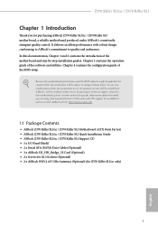
... (Optional) (for specific information about the model you are using. If you for purchasing ASRock Z370 Killer SLI/ac / Z370 Killer SLI motherboard, a reliable motherboard produced under ASRock's consistently stringent quality control. In this documentation, Chapter 1 and 2 contains the introduction of the BIOS setup. Chapter 4 contains the configuration guide of the motherboard and step-by-step installation guides. In case any modifications of this documentation occur, the updated version will be subject to change without further notice. Z370 Killer SLI/ac / Z370 Killer SLI...
... (Optional) (for specific information about the model you are using. If you for purchasing ASRock Z370 Killer SLI/ac / Z370 Killer SLI motherboard, a reliable motherboard produced under ASRock's consistently stringent quality control. In this documentation, Chapter 1 and 2 contains the introduction of the BIOS setup. Chapter 4 contains the configuration guide of the motherboard and step-by-step installation guides. In case any modifications of this documentation occur, the updated version will be subject to change without further notice. Z370 Killer SLI/ac / Z370 Killer SLI...
User Manual
Page 9
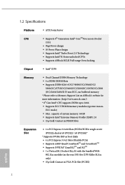
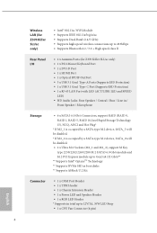
... boot disks • 4 x PCI Express 3.0 x1 Slots (Flexible PCIe) • Supports AMD Quad CrossFireXTM and CrossFireXTM • Supports NVIDIA® Quad SLITM and SLITM • 1 x Vertical M.2 Socket (Key E) with the bundled WiFi- 802.11ac module (on ASRock's website for more information. (http://www.asrock.com/) * 8th Gen Intel® CPU supports DDR4 up to Memory Support List on the rear I/O) (for Z370 Killer SLI/ac only) • 15μ Gold Contact in VGA PCIe Slot...
... boot disks • 4 x PCI Express 3.0 x1 Slots (Flexible PCIe) • Supports AMD Quad CrossFireXTM and CrossFireXTM • Supports NVIDIA® Quad SLITM and SLITM • 1 x Vertical M.2 Socket (Key E) with the bundled WiFi- 802.11ac module (on ASRock's website for more information. (http://www.asrock.com/) * 8th Gen Intel® CPU supports DDR4 up to Memory Support List on the rear I/O) (for Z370 Killer SLI/ac only) • 15μ Gold Contact in VGA PCIe Slot...
User Manual
Page 10
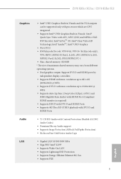
Z370 Killer SLI/ac / Z370 Killer SLI Graphics Audio LAN • Intel® UHD Graphics Built-in Visuals and the VGA outputs can be supported only with processors which are GPU integrated. • Supports Intel® UHD Graphics Built-in Visuals : Intel® Quick Sync Video with max. resolution up to 4K x 2K (4096x2160) @ 30Hz • Supports DVI-D with Content Protection (Realtek ALC892 Audio Codec) • Premium Blu-ray Audio support • Supports Surge...
Z370 Killer SLI/ac / Z370 Killer SLI Graphics Audio LAN • Intel® UHD Graphics Built-in Visuals and the VGA outputs can be supported only with processors which are GPU integrated. • Supports Intel® UHD Graphics Built-in Visuals : Intel® Quick Sync Video with max. resolution up to 4K x 2K (4096x2160) @ 30Hz • Supports DVI-D with Content Protection (Realtek ALC892 Audio Codec) • Premium Blu-ray Audio support • Supports Surge...
User Manual
Page 11
... a SATA-type M.2 device, SATA_0 will be disabled. • 2 x Ultra M.2 Sockets (M2_1 and M2_2), support M Key type 2230/2242/2260/2280 M.2 SATA3 6.0 Gb/s module and M.2 PCI Express module up to Gen3 x4 (32 Gb/s)** ** Supports Intel® OptaneTM Technology ** Supports NVMe SSD as boot disks ** Supports ASRock U.2 Kit Connector • 1 x COM Port Header • 1 x TPM Header • 1 x Chassis Intrusion Header • 1 x Power LED and Speaker Header • 1 x RGB LED Header * Supports in total up to 12V/3A, 36W LED Strip • 1 x CPU Fan Connector (4-pin) English...
... a SATA-type M.2 device, SATA_0 will be disabled. • 2 x Ultra M.2 Sockets (M2_1 and M2_2), support M Key type 2230/2242/2260/2280 M.2 SATA3 6.0 Gb/s module and M.2 PCI Express module up to Gen3 x4 (32 Gb/s)** ** Supports Intel® OptaneTM Technology ** Supports NVMe SSD as boot disks ** Supports ASRock U.2 Kit Connector • 1 x COM Port Header • 1 x TPM Header • 1 x Chassis Intrusion Header • 1 x Power LED and Speaker Header • 1 x RGB LED Header * Supports in total up to 12V/3A, 36W LED Strip • 1 x CPU Fan Connector (4-pin) English...
User Manual
Page 12
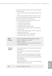
...SLI/ac / Z370 Killer SLI * The CPU Fan Connector supports the CPU fan of maximum 1.5A (18W) fan power. * CHA_FAN2 can auto detect if 3-pin or 4-pin fan is in use. • 1 x 24 pin ATX Power Connector • 1 x 8 pin 12V Power Connector • 1 x Front Panel Audio Connector • 1 x Thunderbolt AIC Connector (5-pin) • 2 x USB 2.0 Headers (Support 4 USB 2.0 ports) (Supports ESD Protection) • 1 x USB 3.1 Gen1 Header (Supports 2 USB 3.1 Gen1 ports) (Supports ESD Protection) • 1 x Front Panel Type C USB 3.1 Gen1 Header • 1 x Performance Mode / Easy OC Header BIOS...
...SLI/ac / Z370 Killer SLI * The CPU Fan Connector supports the CPU fan of maximum 1.5A (18W) fan power. * CHA_FAN2 can auto detect if 3-pin or 4-pin fan is in use. • 1 x 24 pin ATX Power Connector • 1 x 8 pin 12V Power Connector • 1 x Front Panel Audio Connector • 1 x Thunderbolt AIC Connector (5-pin) • 2 x USB 2.0 Headers (Support 4 USB 2.0 ports) (Supports ESD Protection) • 1 x USB 3.1 Gen1 Header (Supports 2 USB 3.1 Gen1 ports) (Supports ESD Protection) • 1 x Front Panel Type C USB 3.1 Gen1 Header • 1 x Performance Mode / Easy OC Header BIOS...
User Manual
Page 14
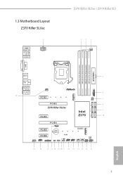
1.3 Motherboard Layout Z370 Killer SLI/ac Z370 Killer SLI/ac / Z370 Killer SLI PS2 Keyboard /Mouse USB 3.1 Gen1 T: USB1 B: USB2 HDMI1 M2_WIFI1 ATX12V1 CPU_FAN1 DDR4_A1 (64 bit, 288-pin module) DDR4_A2 (64 bit, 288-pin module) DDR4_B1 (64 bit, 288-pin module) DDR4_B2 (64 bit, 288-pin module) ATXPWR1 DVI1 USB 3.1 Gen1 T: USB3_TA_1 B: USB3_TC_1 USB 3.1 Gen1 T: USB3 B: USB4 Top: RJ-45 Top: Central/Bass LINE IN Center: REAR SPK Bottom: Optical SPDIF Top: Center: FRONT Bottom: MIC...
1.3 Motherboard Layout Z370 Killer SLI/ac Z370 Killer SLI/ac / Z370 Killer SLI PS2 Keyboard /Mouse USB 3.1 Gen1 T: USB1 B: USB2 HDMI1 M2_WIFI1 ATX12V1 CPU_FAN1 DDR4_A1 (64 bit, 288-pin module) DDR4_A2 (64 bit, 288-pin module) DDR4_B1 (64 bit, 288-pin module) DDR4_B2 (64 bit, 288-pin module) ATXPWR1 DVI1 USB 3.1 Gen1 T: USB3_TA_1 B: USB3_TC_1 USB 3.1 Gen1 T: USB3 B: USB4 Top: RJ-45 Top: Central/Bass LINE IN Center: REAR SPK Bottom: Optical SPDIF Top: Center: FRONT Bottom: MIC...

User Manual
Page 16
... SATA3 Connectors (SATA_0_1) 11 System Panel Header (PANEL1) 12 Power LED and Speaker Header (SPK_PLED1) 13 Chassis Fan / Waterpump Fan Connector (CHA_FAN3/W_PUMP) 14 Chassis Fan Connector (CHA_FAN1) 15 USB 2.0 Header (USB_1_2) 16 USB 2.0 Header (USB_3_4) 17 Performance Mode / Easy OC Header (PM_EO) 18 Chassis Intrusion Header (CI1) 19 RGB LED Header (RGB_LED) 20 Clear CMOS Jumper (CLRMOS1) 21 Thunderbolt AIC Connector (TB2) 22 TPM Header (TPMS1) 23 COM Port Header (COM1) 24 Front Panel Audio Header (HD_AUDIO1) 25 Chassis Fan Connector (CHA_FAN2) 9 English Z370 Killer SLI/ac / Z370 Killer SLI...
... SATA3 Connectors (SATA_0_1) 11 System Panel Header (PANEL1) 12 Power LED and Speaker Header (SPK_PLED1) 13 Chassis Fan / Waterpump Fan Connector (CHA_FAN3/W_PUMP) 14 Chassis Fan Connector (CHA_FAN1) 15 USB 2.0 Header (USB_1_2) 16 USB 2.0 Header (USB_3_4) 17 Performance Mode / Easy OC Header (PM_EO) 18 Chassis Intrusion Header (CI1) 19 RGB LED Header (RGB_LED) 20 Clear CMOS Jumper (CLRMOS1) 21 Thunderbolt AIC Connector (TB2) 22 TPM Header (TPMS1) 23 COM Port Header (COM1) 24 Front Panel Audio Header (HD_AUDIO1) 25 Chassis Fan Connector (CHA_FAN2) 9 English Z370 Killer SLI/ac / Z370 Killer SLI...

User Manual
Page 30
... clear the data in CMOS. To clear and reset the system parameters to short pin2 and pin3 on CLRMOS1 for 15 seconds, use a jumper cap to default setup, please turn off the computer and unplug the power cord from the power supply. When the jumper cap is placed on the pins, the jumper is "Open". If no jumper cap is placed on the pins, the jumper is "Short". English 23 Z370 Killer SLI/ac / Z370 Killer SLI 2.5 Jumpers Setup...
... clear the data in CMOS. To clear and reset the system parameters to short pin2 and pin3 on CLRMOS1 for 15 seconds, use a jumper cap to default setup, please turn off the computer and unplug the power cord from the power supply. When the jumper cap is placed on the pins, the jumper is "Open". If no jumper cap is placed on the pins, the jumper is "Short". English 23 Z370 Killer SLI/ac / Z370 Killer SLI 2.5 Jumpers Setup...
User Manual
Page 32
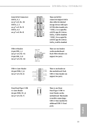
... one header on this motherboard. This header is occupied by a SATA-type M.2 device, SATA_5 will be disabled. Each USB 3.1 Gen1 header can support two ports. Z370 Killer SLI/ac / Z370 Killer SLI Serial ATA3 Connectors (SATA_0_1: see p.7 or 8, No. 10) (SATA_2_3: see p.7 or 8, No. 9) (SATA_4_5: see p.7 or 8, No. 8) USB 2.0 Headers (9-pin USB_1_2 (see p.7 or 8, No. 15) (9-pin USB_3_4) (see p.7 or 8, No. 16) SATA_0 SATA_2 SATA_4 SATA_1 SATA_3 SATA_5 These six SATA3 connectors support SATA data cables for internal storage devices with...
... one header on this motherboard. This header is occupied by a SATA-type M.2 device, SATA_5 will be disabled. Each USB 3.1 Gen1 header can support two ports. Z370 Killer SLI/ac / Z370 Killer SLI Serial ATA3 Connectors (SATA_0_1: see p.7 or 8, No. 10) (SATA_2_3: see p.7 or 8, No. 9) (SATA_4_5: see p.7 or 8, No. 8) USB 2.0 Headers (9-pin USB_1_2 (see p.7 or 8, No. 15) (9-pin USB_3_4) (see p.7 or 8, No. 16) SATA_0 SATA_2 SATA_4 SATA_1 SATA_3 SATA_5 These six SATA3 connectors support SATA data cables for internal storage devices with...
User Manual
Page 34
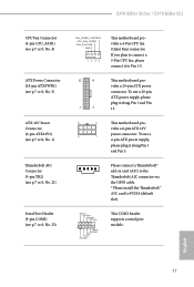
... Thunderbolt AIC connector via the GPIO cable. * Please install the Thunderbolt™ AIC card to Pin 1-3. 12 24 1 13 This motherboard provides a 24-pin ATX power connector. If you plan to connect a 3-Pin CPU fan, please connect it to PCIE4 (default slot). RRXD1 DDTR#1 DDSR#1 CCTS#1 1 RRI#1 RRTS#1 GND TTXD1 DDCD#1 This COM1 header supports a serial port module. English 27 Z370 Killer SLI/ac / Z370 Killer SLI CPU Fan Connector (4-pin CPU_FAN1) (see p.7 or 8, No. 4) ATX Power Connector (24-pin ATXPWR1) (see p.7 or 8, No. 5) ATX 12V Power Connector (8-pin ATX12V1...
... Thunderbolt AIC connector via the GPIO cable. * Please install the Thunderbolt™ AIC card to Pin 1-3. 12 24 1 13 This motherboard provides a 24-pin ATX power connector. If you plan to connect a 3-Pin CPU fan, please connect it to PCIE4 (default slot). RRXD1 DDTR#1 DDSR#1 CCTS#1 1 RRI#1 RRTS#1 GND TTXD1 DDCD#1 This COM1 header supports a serial port module. English 27 Z370 Killer SLI/ac / Z370 Killer SLI CPU Fan Connector (4-pin CPU_FAN1) (see p.7 or 8, No. 4) ATX Power Connector (24-pin ATXPWR1) (see p.7 or 8, No. 5) ATX 12V Power Connector (8-pin ATX12V1...
User Manual
Page 36
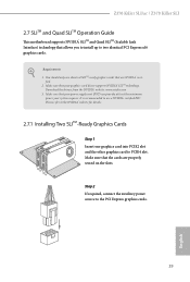
... minimum power your graphics card driver supports NVIDIA® SLITM technology. Please refer to the NVIDIA® website for details. 2.7.1 Installing Two SLITM-Ready Graphics Cards Step 1 Insert one graphics card into PCIE2 slot and the other graphics card to the PCI Express graphics cards. 29 English Z370 Killer SLI/ac / Z370 Killer SLI 2.7 SLITM and Quad SLITM Operation Guide This motherboard supports NVIDIA® SLITM and Quad SLITM (Scalable Link Interface) technology that allows you to install up to use...
... minimum power your graphics card driver supports NVIDIA® SLITM technology. Please refer to the NVIDIA® website for details. 2.7.1 Installing Two SLITM-Ready Graphics Cards Step 1 Insert one graphics card into PCIE2 slot and the other graphics card to the PCI Express graphics cards. 29 English Z370 Killer SLI/ac / Z370 Killer SLI 2.7 SLITM and Quad SLITM Operation Guide This motherboard supports NVIDIA® SLITM and Quad SLITM (Scalable Link Interface) technology that allows you to install up to use...
User Manual
Page 39
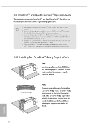
Please refer to AMD graphics card manuals for detailed installation guide. 2.8.1 Installing Two CrossFireXTM-Ready Graphics Cards Step 1 Insert one graphics card into PCIE2 slot and the other graphics card to enable CrossFireXTM. Different CrossFireXTM cards may require different methods to PCIE4 slot. Download the drivers from the AMD's website: www.amd.com 3. Make sure that the cards are AMD certified. 2. Make sure that your graphics card driver supports AMD CrossFireXTM technology. CrossFire Bridge Step 2 Connect two graphics cards by installing a CrossFire Bridge on...
Please refer to AMD graphics card manuals for detailed installation guide. 2.8.1 Installing Two CrossFireXTM-Ready Graphics Cards Step 1 Insert one graphics card into PCIE2 slot and the other graphics card to enable CrossFireXTM. Different CrossFireXTM cards may require different methods to PCIE4 slot. Download the drivers from the AMD's website: www.amd.com 3. Make sure that the cards are AMD certified. 2. Make sure that your graphics card driver supports AMD CrossFireXTM technology. CrossFire Bridge Step 2 Connect two graphics cards by installing a CrossFire Bridge on...
User Manual
Page 41
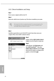
... graphics card and click Apply. English 34 The Catalyst Uninstaller is an optional download. Step 5 In the left pane, click Performance and then AMD CrossFireXTM. 2.8.2 Driver Installation and Setup Step 1 Power on your computer. Step 3 Install the required drivers and CATALYST Control Center then restart your computer and boot into OS. Then select Enable AMD CrossFireX and click Apply. Please check AMD's website for AMD driver updates. We recommend using...
... graphics card and click Apply. English 34 The Catalyst Uninstaller is an optional download. Step 5 In the left pane, click Performance and then AMD CrossFireXTM. 2.8.2 Driver Installation and Setup Step 1 Power on your computer. Step 3 Install the required drivers and CATALYST Control Center then restart your computer and boot into OS. Then select Enable AMD CrossFireX and click Apply. Please check AMD's website for AMD driver updates. We recommend using...
User Manual
Page 46
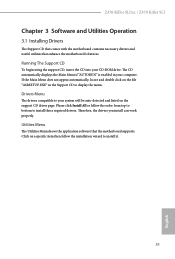
... be auto-detected and listed on a specific item then follow the order from top to bottom to install it. 39 English Please click Install All or follow the installation wizard to install those required drivers. Utilities Menu The Utilities Menu shows the application software that enhance the motherboard's features. Z370 Killer SLI/ac / Z370 Killer SLI Chapter 3 Software and Utilities Operation 3.1 Installing Drivers The Support CD that comes with the motherboard contains necessary drivers and useful utilities that the motherboard supports. Drivers Menu The drivers compatible...
... be auto-detected and listed on a specific item then follow the order from top to bottom to install it. 39 English Please click Install All or follow the installation wizard to install those required drivers. Utilities Menu The Utilities Menu shows the application software that enhance the motherboard's features. Z370 Killer SLI/ac / Z370 Killer SLI Chapter 3 Software and Utilities Operation 3.1 Installing Drivers The Support CD that comes with the motherboard contains necessary drivers and useful utilities that the motherboard supports. Drivers Menu The drivers compatible...
User Manual
Page 77
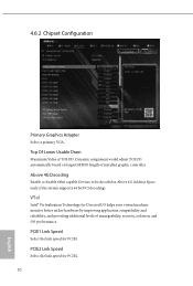
... Directed I /O performance. PCIE1 Link Speed Select the link speed for PCIE2. 70 English PCIE2 Link Speed Select the link speed for PCIE1. Above 4G Decoding Enable or disable 64bit capable Devices to be decoded in Above 4G Address Space (only if the system supports 64 bit PCI decoding). Dynamic assignment would adjust TOLUD automatically based on largest MMIO length of installed graphic controller.
... Directed I /O performance. PCIE1 Link Speed Select the link speed for PCIE2. 70 English PCIE2 Link Speed Select the link speed for PCIE1. Above 4G Decoding Enable or disable 64bit capable Devices to be decoded in Above 4G Address Space (only if the system supports 64 bit PCI decoding). Dynamic assignment would adjust TOLUD automatically based on largest MMIO length of installed graphic controller.
User Manual
Page 79
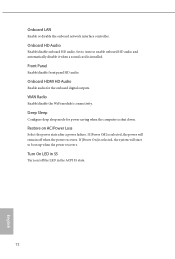
Deep Sleep Configure deep sleep mode for the onboard digital outputs. Turn On LED in the ACPI S5 state. 72 English Onboard HDMI HD Audio Enable audio for power saving when the computer is selected, the power will start to enable onboard HD audio and automatically disable it when a sound card is selected, the system will remain off the LED in S5 Turn on AC/Power Loss Select the power state after a power failure. Front Panel Enable/disable front panel HD audio. If [Power Off] is...
Deep Sleep Configure deep sleep mode for the onboard digital outputs. Turn On LED in the ACPI S5 state. 72 English Onboard HDMI HD Audio Enable audio for power saving when the computer is selected, the power will start to enable onboard HD audio and automatically disable it when a sound card is selected, the system will remain off the LED in S5 Turn on AC/Power Loss Select the power state after a power failure. Front Panel Enable/disable front panel HD audio. If [Power Off] is...
User Manual
Page 88
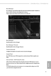
Instant Flash Save UEFI files in your USB storage device and run Instant Flash to plug in your UEFI. Please setup network configuration before using this tool. Timeout Seconds Configure the number of seconds to use this function. 81 English Boot Manager Enable/disable the Boot Manager. Boot Manager Timeout Enable/disable the Boot Manager Timeout. Internet Flash - DHCP (Auto IP), Auto ASRock Internet Flash downloads and updates the latest UEFI firmware version from our servers for the Boot Manager. Z370 Killer SLI/ac / Z370 Killer SLI Boot Manager Boot Manager is ...
Instant Flash Save UEFI files in your USB storage device and run Instant Flash to plug in your UEFI. Please setup network configuration before using this tool. Timeout Seconds Configure the number of seconds to use this function. 81 English Boot Manager Enable/disable the Boot Manager. Boot Manager Timeout Enable/disable the Boot Manager Timeout. Internet Flash - DHCP (Auto IP), Auto ASRock Internet Flash downloads and updates the latest UEFI firmware version from our servers for the Boot Manager. Z370 Killer SLI/ac / Z370 Killer SLI Boot Manager Boot Manager is ...
User Manual
Page 89
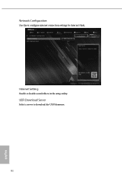
Network Configuration Use this to download the UEFI firmware. 82 English UEFI Download Server Select a server to configure internet connection settings for Internet Flash. Internet Setting Enable or disable sound effects in the setup utility.
Network Configuration Use this to download the UEFI firmware. 82 English UEFI Download Server Select a server to configure internet connection settings for Internet Flash. Internet Setting Enable or disable sound effects in the setup utility.
User Manual
Page 93
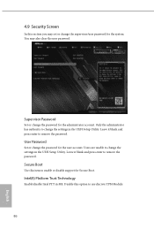
... enter to remove the password. Secure Boot Use this section you may also clear the user password. Intel(R) Platform Trust Technology Enable/disable Intel PTT in the UEFI Setup Utility. 4.9 Security Screen In this item to enable or disable support for Secure Boot. Supervisor Password Set or change the settings in the UEFI Setup Utility. Users are unable to change the password for the system. Only the administrator has authority to change the password for the administrator account. Disable this option to remove the password...
... enter to remove the password. Secure Boot Use this section you may also clear the user password. Intel(R) Platform Trust Technology Enable/disable Intel PTT in the UEFI Setup Utility. 4.9 Security Screen In this item to enable or disable support for Secure Boot. Supervisor Password Set or change the settings in the UEFI Setup Utility. Users are unable to change the password for the system. Only the administrator has authority to change the password for the administrator account. Disable this option to remove the password...


