

User Manual
Page 4
... I/O Panel 8 Chapter 2 Installation 10 2.1 Installing the CPU 11 2.2 Installing the CPU Fan and Heatsink 14 2.3 Installing Memory Modules (DIMM) 15 2.4 Expansion Slots (PCI Express Slots) 17 2.5 Jumpers Setup 18 2.6 Onboard Headers and Connectors 19 2.7 CrossFireXTM and Quad CrossFireXTM Operation Guide 24 2.7.1 Installing Two CrossFireXTM-Ready Graphics Cards 24 2.7.2 Driver Installation and Setup 26 2.8 M.2_SSD (NGFF) Module Installation Guide 27 Chapter 3 Software and Utilities Operation 30 3.1 Installing Drivers 30 3.2 A-Tuning 31 3.3 ASRock Live Update & APP...
... I/O Panel 8 Chapter 2 Installation 10 2.1 Installing the CPU 11 2.2 Installing the CPU Fan and Heatsink 14 2.3 Installing Memory Modules (DIMM) 15 2.4 Expansion Slots (PCI Express Slots) 17 2.5 Jumpers Setup 18 2.6 Onboard Headers and Connectors 19 2.7 CrossFireXTM and Quad CrossFireXTM Operation Guide 24 2.7.1 Installing Two CrossFireXTM-Ready Graphics Cards 24 2.7.2 Driver Installation and Setup 26 2.8 M.2_SSD (NGFF) Module Installation Guide 27 Chapter 3 Software and Utilities Operation 30 3.1 Installing Drivers 30 3.2 A-Tuning 31 3.3 ASRock Live Update & APP...
User Manual
Page 5
... BIOS & Drivers 39 3.3.4 Setting 40 3.4 Enabling USB Ports for Windows® 7 Installation 41 Chapter 4 UEFI SETUP UTILITY 44 4.1 Introduction 44 4.1.1 UEFI Menu Bar 44 4.1.2 Navigation Keys 45 4.2 Main Screen 46 4.3 OC Tweaker Screen 47 4.4 Advanced Screen 57 4.4.1 CPU Configuration 58 4.4.2 Chipset Configuration 60 4.4.3 Storage Configuration 62 4.4.4 Super IO Configuration 63 4.4.5 ACPI Configuration 64 4.4.6 USB Configuration 66 4.4.7 Trusted Computing 67 4.5 Tools 68 4.6 Hardware Health Event Monitoring Screen 72 4.7 Security Screen 74 4.8 Boot...
... BIOS & Drivers 39 3.3.4 Setting 40 3.4 Enabling USB Ports for Windows® 7 Installation 41 Chapter 4 UEFI SETUP UTILITY 44 4.1 Introduction 44 4.1.1 UEFI Menu Bar 44 4.1.2 Navigation Keys 45 4.2 Main Screen 46 4.3 OC Tweaker Screen 47 4.4 Advanced Screen 57 4.4.1 CPU Configuration 58 4.4.2 Chipset Configuration 60 4.4.3 Storage Configuration 62 4.4.4 Super IO Configuration 63 4.4.5 ACPI Configuration 64 4.4.6 USB Configuration 66 4.4.7 Trusted Computing 67 4.5 Tools 68 4.6 Hardware Health Event Monitoring Screen 72 4.7 Security Screen 74 4.8 Boot...

User Manual
Page 6
... using. In this documentation will be updated, the content of this documentation, Chapter 1 and 2 contains the introduction of this motherboard, please visit our website for specific information about the model you for M.2 Socket 1 English ASRock website http://www.asrock.com. 1.1 Package Contents • ASRock Z170 Pro4 Motherboard (ATX Form Factor) • ASRock Z170 Pro4 Quick Installation Guide • ASRock Z170 Pro4 Support CD • 2 x Serial ATA (SATA) Data Cables (Optional) • 1 x I/O Panel Shield • 1 x Screw for purchasing ASRock Z170 Pro4 motherboard...
... using. In this documentation will be updated, the content of this documentation, Chapter 1 and 2 contains the introduction of this motherboard, please visit our website for specific information about the model you for M.2 Socket 1 English ASRock website http://www.asrock.com. 1.1 Package Contents • ASRock Z170 Pro4 Motherboard (ATX Form Factor) • ASRock Z170 Pro4 Quick Installation Guide • ASRock Z170 Pro4 Support CD • 2 x Serial ATA (SATA) Data Cables (Optional) • 1 x I/O Panel Shield • 1 x Screw for purchasing ASRock Z170 Pro4 motherboard...
User Manual
Page 9
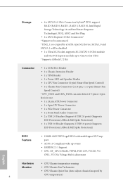
...® Z170, support RAID (RAID 0, RAID 1, RAID 5, RAID 10, Intel Rapid Storage Technology 14 and Intel Smart Response Technology), NCQ, AHCI and Hot Plug • 2 x SATA Express 10 Gb/s Connectors* * Support to be disabled. • 1 x Ultra M.2 Socket, supports M.2 SATA3 6.0 Gb/s module and M.2 PCI Express module up to Gen3 x4 (32 Gb/s) * Supports ASRock U.2 Kit Connector • 1 x COM Port Header • 1 x Chassis Intrusion Header • 1 x TPM Header • 1 x Power LED and Speaker Header • 1 x CPU Fan Connector (4-pin) (Smart Fan Speed Control) • 3 x Chassis Fan...
...® Z170, support RAID (RAID 0, RAID 1, RAID 5, RAID 10, Intel Rapid Storage Technology 14 and Intel Smart Response Technology), NCQ, AHCI and Hot Plug • 2 x SATA Express 10 Gb/s Connectors* * Support to be disabled. • 1 x Ultra M.2 Socket, supports M.2 SATA3 6.0 Gb/s module and M.2 PCI Express module up to Gen3 x4 (32 Gb/s) * Supports ASRock U.2 Kit Connector • 1 x COM Port Header • 1 x Chassis Intrusion Header • 1 x TPM Header • 1 x Power LED and Speaker Header • 1 x CPU Fan Connector (4-pin) (Smart Fan Speed Control) • 3 x Chassis Fan...
User Manual
Page 10
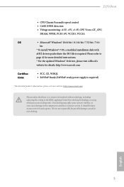
... with xHCI drivers packed into the ISO file is required. Z170 Pro4 • CPU/Chassis Fan multi-speed control • CASE OPEN detection • Voltage monitoring: +12V, +5V, +3.3V, CPU Vcore, GT_CPU, DRAM, VPPM, PCH 1.0V, VCCIO, VCCSA OS • Microsoft® Windows® 10 64-bit / 8.1 64-bit / 7 32-bit / 7 64- bit * To install Windows® 7 OS, a modified installation disk with overclocking, including adjusting the setting in the BIOS, applying Untied Overclocking Technology, or using third-party overclocking tools...
... with xHCI drivers packed into the ISO file is required. Z170 Pro4 • CPU/Chassis Fan multi-speed control • CASE OPEN detection • Voltage monitoring: +12V, +5V, +3.3V, CPU Vcore, GT_CPU, DRAM, VPPM, PCH 1.0V, VCCIO, VCCSA OS • Microsoft® Windows® 10 64-bit / 8.1 64-bit / 7 32-bit / 7 64- bit * To install Windows® 7 OS, a modified installation disk with overclocking, including adjusting the setting in the BIOS, applying Untied Overclocking Technology, or using third-party overclocking tools...
User Manual
Page 22
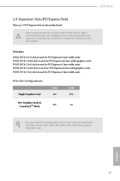
... PCIe slots: PCIE1 (PCIe 3.0 x1 slot) is used for PCI Express x4 lane width graphics cards. PCIe Slot Configurations Single Graphics Card PCIE2 x16 PCIE4 N/A Two Graphics Cards in CrossFireXTM Mode x16 x4 For a better thermal environment, please connect a chassis fan to the motherboard's chassis fan connector (CHA_FAN1, CHA_FAN2 or CHA_FAN3) when using multiple graphics cards. Z170 Pro4 2.4 Expansion Slots (PCI Express Slots) There are 5 PCI Express slots on the motherboard. Please read the documentation of the expansion card and make sure that the power supply is switched...
... PCIe slots: PCIE1 (PCIe 3.0 x1 slot) is used for PCI Express x4 lane width graphics cards. PCIe Slot Configurations Single Graphics Card PCIE2 x16 PCIE4 N/A Two Graphics Cards in CrossFireXTM Mode x16 x4 For a better thermal environment, please connect a chassis fan to the motherboard's chassis fan connector (CHA_FAN1, CHA_FAN2 or CHA_FAN3) when using multiple graphics cards. Z170 Pro4 2.4 Expansion Slots (PCI Express Slots) There are 5 PCI Express slots on the motherboard. Please read the documentation of the expansion card and make sure that the power supply is switched...
User Manual
Page 23
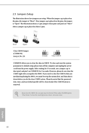
... reset the system parameters to short pin2 and pin3 on CLRMOS1 for 15 seconds, use a jumper cap to default setup, please turn off the computer and unplug the power cord from the power supply. English 18 After waiting for 5 seconds. When the jumper cap is placed on the pins, the jumper is "Open". Please adjust the BIOS option "Clear Status" to clear the CMOS when you just finish updating...
... reset the system parameters to short pin2 and pin3 on CLRMOS1 for 15 seconds, use a jumper cap to default setup, please turn off the computer and unplug the power cord from the power supply. English 18 After waiting for 5 seconds. When the jumper cap is placed on the pins, the jumper is "Open". Please adjust the BIOS option "Clear Status" to clear the CMOS when you just finish updating...
User Manual
Page 24
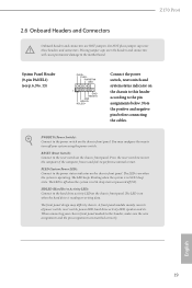
Z170 Pro4 2.6 Onboard Headers and Connectors Onboard headers and connectors are matched correctly. You may differ by chassis. HDLED (Hard Drive Activity LED): Connect to turn off your chassis front panel module to the pin assignments below. A front panel module mainly consists of power switch, reset switch, power LED, hard drive activity LED, speaker and etc. System Panel Header (9-pin PANEL1) (see p.6, No. 13) PLED+ PLEDPWRBTN# GND 1 GND RESET# GND HDLEDHDLED+ Connect the power switch, reset switch and system status indicator on when the hard drive is operating. The LED ...
Z170 Pro4 2.6 Onboard Headers and Connectors Onboard headers and connectors are matched correctly. You may differ by chassis. HDLED (Hard Drive Activity LED): Connect to turn off your chassis front panel module to the pin assignments below. A front panel module mainly consists of power switch, reset switch, power LED, hard drive activity LED, speaker and etc. System Panel Header (9-pin PANEL1) (see p.6, No. 13) PLED+ PLEDPWRBTN# GND 1 GND RESET# GND HDLEDHDLED+ Connect the power switch, reset switch and system status indicator on when the hard drive is operating. The LED ...

User Manual
Page 28
... platform integrity. This feature requires a chassis with chassis intrusion detection design. English 23 PCIe Power Connector (4-pin PCIE_PWR1) (see p.6, No. 21) 1 GND Signal This motherboard supports CASE OPEN detection feature that detects if the chassis cove has been removed. Z170 Pro4 Chassis Intrusion Header (2-pin CI1) (see p.6, No. 27) GND +12V DETECT Please connect a 4 pin molex power cable to this connector when more than three graphics cards are installed. GND SMB_CLK_MAIN SMB_DATA_MAIN LAD2 LAD1...
... platform integrity. This feature requires a chassis with chassis intrusion detection design. English 23 PCIe Power Connector (4-pin PCIE_PWR1) (see p.6, No. 21) 1 GND Signal This motherboard supports CASE OPEN detection feature that detects if the chassis cove has been removed. Z170 Pro4 Chassis Intrusion Header (2-pin CI1) (see p.6, No. 27) GND +12V DETECT Please connect a 4 pin molex power cable to this connector when more than three graphics cards are installed. GND SMB_CLK_MAIN SMB_DATA_MAIN LAD2 LAD1...
User Manual
Page 29
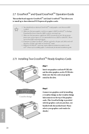
... use identical CrossFireXTM-ready graphics cards that the cards are AMD certified. 2. You should only use a AMD certified PSU. Download the drivers from the AMD's website: www.amd.com 3. Please refer to AMD graphics card manuals for detailed installation guide. 2.7.1 Installing Two CrossFireXTM-Ready Graphics Cards Step 1 Insert one graphics card into PCIE2 slot and the other graphics card to enable CrossFireXTM. Make sure that your power supply unit (PSU) can provide at least the minimum power your graphics card driver supports AMD CrossFireXTM technology...
... use identical CrossFireXTM-ready graphics cards that the cards are AMD certified. 2. You should only use a AMD certified PSU. Download the drivers from the AMD's website: www.amd.com 3. Please refer to AMD graphics card manuals for detailed installation guide. 2.7.1 Installing Two CrossFireXTM-Ready Graphics Cards Step 1 Insert one graphics card into PCIE2 slot and the other graphics card to enable CrossFireXTM. Make sure that your power supply unit (PSU) can provide at least the minimum power your graphics card driver supports AMD CrossFireXTM technology...
User Manual
Page 31
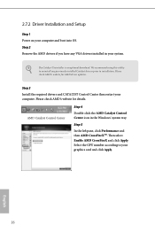
... boot into OS. We recommend using this utility to installation. Then select Enable AMD CrossFireX and click Apply. Please check AMD's website for AMD driver updates. Step 5 In the left pane, click Performance and then AMD CrossFireXTM. 2.7.2 Driver Installation and Setup Step 1 Power on your graphics card and click Apply. Step 3 Install the required drivers and CATALYST Control Center then restart your system. Step 2 Remove the AMD drivers if you have any previously installed...
... boot into OS. We recommend using this utility to installation. Then select Enable AMD CrossFireX and click Apply. Please check AMD's website for AMD driver updates. Step 5 In the left pane, click Performance and then AMD CrossFireXTM. 2.7.2 Driver Installation and Setup Step 1 Power on your graphics card and click Apply. Step 3 Install the required drivers and CATALYST Control Center then restart your system. Step 2 Remove the AMD drivers if you have any previously installed...
User Manual
Page 35
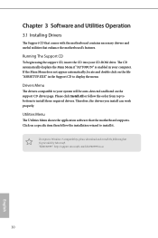
...-ROM drive. Click on the support CD driver page. If the Main Menu does not appear automatically, locate and double click on the file "ASRSETUP.EXE" in your computer. Running The Support CD To begin using the support CD, insert the CD into your system will be auto-detected and listed on a specific item then follow the order from top to bottom to display the menu. Utilities Menu...
...-ROM drive. Click on the support CD driver page. If the Main Menu does not appear automatically, locate and double click on the file "ASRSETUP.EXE" in your computer. Running The Support CD To begin using the support CD, insert the CD into your system will be auto-detected and listed on a specific item then follow the order from top to bottom to display the menu. Utilities Menu...
User Manual
Page 46
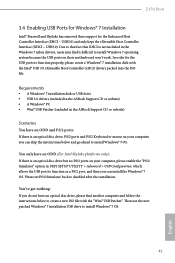
.../2 Simulator" option in UEFI SETUP UTILITY > Advanced > USB Configuration, which allows the USB port to function as a PS/2 port, and then you can skip the instructions below to create a new ISO file with the Intel® USB 3.0 eXtensible Host Controller (xHCI) drivers packed into the ISO file. USB2.0) and only kept the eXtensible Host Controller Interface (XHCI - Requirements • A Windows® 7 installation disk or USB drive • USB 3.0 drivers (included in the ASRock Support CD...
.../2 Simulator" option in UEFI SETUP UTILITY > Advanced > USB Configuration, which allows the USB port to function as a PS/2 port, and then you can skip the instructions below to create a new ISO file with the Intel® USB 3.0 eXtensible Host Controller (xHCI) drivers packed into the ISO file. USB2.0) and only kept the eXtensible Host Controller Interface (XHCI - Requirements • A Windows® 7 installation disk or USB drive • USB 3.0 drivers (included in the ASRock Support CD...
User Manual
Page 47
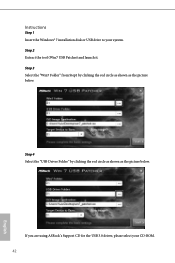
Step 3 Select the "Win7 Folder" from Step1 by clicking the red circle as shown as the picture below . Instructions Step 1 Insert the Windows® 7 installation disk or USB drive to your CD-ROM. 42 English Step 2 Extract the tool (Win7 USB Patcher) and launch it. If you are using ASRock's Support CD for the USB 3.0 driver, please select your system. Step 4 Select the "USB Driver Folder" by clicking the red circle as shown as the picture below .
Step 3 Select the "Win7 Folder" from Step1 by clicking the red circle as shown as the picture below . Instructions Step 1 Insert the Windows® 7 installation disk or USB drive to your CD-ROM. 42 English Step 2 Extract the tool (Win7 USB Patcher) and launch it. If you are using ASRock's Support CD for the USB 3.0 driver, please select your system. Step 4 Select the "USB Driver Folder" by clicking the red circle as shown as the picture below .
User Manual
Page 66
...-Monitor Select disable to enable onboard HD audio and automatically disable it when a sound card is installed. Set to Auto to disable the integrated graphics when an external graphics card is installed. If [Power Off] is idle for all times. It will remain off when the power recovers. Front Panel Enable/disable front panel HD audio. Inte(R) Ethernet Connection I219-V Enable or disable the onboard network interface controller (Intel® I219V). Restore on . Z170 Pro4 PCH DMI ASPM Support This option enables/disables the ASPM support...
...-Monitor Select disable to enable onboard HD audio and automatically disable it when a sound card is installed. Set to Auto to disable the integrated graphics when an external graphics card is installed. If [Power Off] is idle for all times. It will remain off when the power recovers. Front Panel Enable/disable front panel HD audio. Inte(R) Ethernet Connection I219-V Enable or disable the onboard network interface controller (Intel® I219V). Restore on . Z170 Pro4 PCH DMI ASPM Support This option enables/disables the ASPM support...
User Manual
Page 68
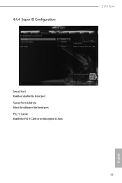
Serial Port Address Select the address of the Serial port. 4.4.4 Super IO Configuration Z170 Pro4 Serial Port Enable or disable the Serial port. PS2 Y-Cable Enable the PS2 Y-Cable or set this option to Auto. 63 English
Serial Port Address Select the address of the Serial port. 4.4.4 Super IO Configuration Z170 Pro4 Serial Port Enable or disable the Serial port. PS2 Y-Cable Enable the PS2 Y-Cable or set this option to Auto. 63 English
User Manual
Page 74
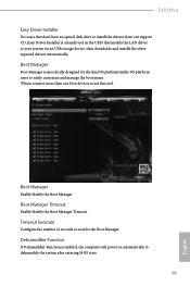
... tool in the UEFI that installs the LAN driver to your system via an USB storage device, then downloads and installs the other required drivers automatically. Boot Manager Timeout Enable/disable the Boot Manager Timeout. Z170 Pro4 Easy Driver Installer For users that don't have an optical disk drive to install the drivers from our support CD, Easy Driver Installer is specifically designed for the Boot Manager. Dehumidifier Function If Dehumidifier Function is enabled, the computer will power on automatically...
... tool in the UEFI that installs the LAN driver to your system via an USB storage device, then downloads and installs the other required drivers automatically. Boot Manager Timeout Enable/disable the Boot Manager Timeout. Z170 Pro4 Easy Driver Installer For users that don't have an optical disk drive to install the drivers from our support CD, Easy Driver Installer is specifically designed for the Boot Manager. Dehumidifier Function If Dehumidifier Function is enabled, the computer will power on automatically...
User Manual
Page 75
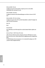
... your USB storage device and run Instant Flash to S4/S5 state. Dehumidifier Duration Configure the duration of the dehumidifying process before using Internet Flash. *For BIOS backup and recovery purpose, it returns to update your USB pen drive before it is enabled. Dehumidifier CPU Fan Setting Configure the speed of time until the computer powers on and enables Dehumidifier after entering S4/S5 state. Max: 255 Min: 1 Instant Flash Save UEFI files in your UEFI...
... your USB storage device and run Instant Flash to S4/S5 state. Dehumidifier Duration Configure the duration of the dehumidifying process before using Internet Flash. *For BIOS backup and recovery purpose, it returns to update your USB pen drive before it is enabled. Dehumidifier CPU Fan Setting Configure the speed of time until the computer powers on and enables Dehumidifier after entering S4/S5 state. Max: 255 Min: 1 Instant Flash Save UEFI files in your UEFI...
User Manual
Page 76
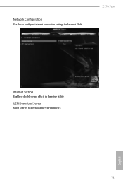
UEFI Download Server Select a server to configure internet connection settings for Internet Flash. English 71 Network Configuration Use this to download the UEFI firmware. Z170 Pro4 Internet Setting Enable or disable sound effects in the setup utility.
UEFI Download Server Select a server to configure internet connection settings for Internet Flash. English 71 Network Configuration Use this to download the UEFI firmware. Z170 Pro4 Internet Setting Enable or disable sound effects in the setup utility.
User Manual
Page 79
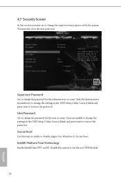
... remove the password. User Password Set or change the password for the administrator account. Intel(R) Platform Trust Technology Enable/disable Intel PTT in the UEFI Setup Utility. Leave it blank and press enter to use discrete TPM Module. 74 English Supervisor Password Set or change the password for the user account. 4.7 Security Screen In this section you may also clear the user password. Users are unable to enable or disable support for the system. Secure Boot Use this option to remove the password. Disable...
... remove the password. User Password Set or change the password for the administrator account. Intel(R) Platform Trust Technology Enable/disable Intel PTT in the UEFI Setup Utility. Leave it blank and press enter to use discrete TPM Module. 74 English Supervisor Password Set or change the password for the user account. 4.7 Security Screen In this section you may also clear the user password. Users are unable to enable or disable support for the system. Secure Boot Use this option to remove the password. Disable...


