

User Manual
Page 5
... Setup 37 2.11 M.2_SSD (NGFF) Module Installation Guide 38 Chapter 3 Software and Utilities Operation 41 3.1 Installing Drivers 41 3.2 A-Tuning 42 3.3 ASRock Live Update & APP Shop 46 3.3.1 UI Overview 46 3.3.2 Apps 47 3.3.3 BIOS & Drivers 50 3.3.4 Setting 51 3.4 Enabling USB Ports for Windows® 7 Installation 52 Chapter 4 UEFI SETUP UTILITY 55 4.1 Introduction 55 4.1.1 UEFI...
... Setup 37 2.11 M.2_SSD (NGFF) Module Installation Guide 38 Chapter 3 Software and Utilities Operation 41 3.1 Installing Drivers 41 3.2 A-Tuning 42 3.3 ASRock Live Update & APP Shop 46 3.3.1 UI Overview 46 3.3.2 Apps 47 3.3.3 BIOS & Drivers 50 3.3.4 Setting 51 3.4 Enabling USB Ports for Windows® 7 Installation 52 Chapter 4 UEFI SETUP UTILITY 55 4.1 Introduction 55 4.1.1 UEFI...
User Manual
Page 7
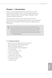
... and step-by-step installation guides. You may ind the latest VGA cards and CPU support list on ASRock's website without notice. ASRock website http://www.asrock.com. 1.1 Package Contents • ASRock Z170 Extreme7 Motherboard (ATX Form Factor) • ASRock Z170 Extreme7 Quick Installation Guide • ASRock Z170 Extreme7 Support CD • 4 x Serial ATA (SATA) Data Cables (Optional) • 1 x I/O Panel Shield •...
... and step-by-step installation guides. You may ind the latest VGA cards and CPU support list on ASRock's website without notice. ASRock website http://www.asrock.com. 1.1 Package Contents • ASRock Z170 Extreme7 Motherboard (ATX Form Factor) • ASRock Z170 Extreme7 Quick Installation Guide • ASRock Z170 Extreme7 Support CD • 4 x Serial ATA (SATA) Data Cables (Optional) • 1 x I/O Panel Shield •...

User Manual
Page 11
...ASRock Full Spike Protection)) • 1 x Dr. Debug with LED • 1 x Power Switch with LED • 1 x Reset Switch with LED • 1 x Clear CMOS Switch • 1 x BIOS Selection Switch BIOS • 2 x 128Mb AMI UEFI Legal BIOS with multilingual GUI Feature support (1 x Main BIOS and 1 x Backup BIOS... • SMBIOS 2.3.1 Support • CPU, GT_CPU, DRAM, VPPM, PCH 1.0V, VCCIO, VC- Z170 Extreme7+ • 3 x SATA Express 10 Gb/s Connectors* * Support to Gen3 x4 (32 Gb/s) * Supports ASRock U.2 Kit Connector • 1 x COM Port Header • 1 x TPM Header • 1 ...
...ASRock Full Spike Protection)) • 1 x Dr. Debug with LED • 1 x Power Switch with LED • 1 x Reset Switch with LED • 1 x Clear CMOS Switch • 1 x BIOS Selection Switch BIOS • 2 x 128Mb AMI UEFI Legal BIOS with multilingual GUI Feature support (1 x Main BIOS and 1 x Backup BIOS... • SMBIOS 2.3.1 Support • CPU, GT_CPU, DRAM, VPPM, PCH 1.0V, VCCIO, VC- Z170 Extreme7+ • 3 x SATA Express 10 Gb/s Connectors* * Support to Gen3 x4 (32 Gb/s) * Supports ASRock U.2 Kit Connector • 1 x COM Port Header • 1 x TPM Header • 1 ...

User Manual
Page 12
...'s stability, or even cause damage to page 52 for more detailed instructions. * For the updated Windows® 10 driver, please visit ASRock's website for possible damage caused by CPU temperature) • CPU/Chassis Fan multi-speed control • Voltage monitoring: +12V, +5V, ... installation disk with xHCI drivers packed into the ISO ile is a certain risk involved with overclocking, including adjusting the setting in the BIOS, applying Untied Overclocking Technology, or using third-party overclocking tools. English 6 It should be done at your system. Hardware Monitor •...
...'s stability, or even cause damage to page 52 for more detailed instructions. * For the updated Windows® 10 driver, please visit ASRock's website for possible damage caused by CPU temperature) • CPU/Chassis Fan multi-speed control • Voltage monitoring: +12V, +5V, ... installation disk with xHCI drivers packed into the ISO ile is a certain risk involved with overclocking, including adjusting the setting in the BIOS, applying Untied Overclocking Technology, or using third-party overclocking tools. English 6 It should be done at your system. Hardware Monitor •...

User Manual
Page 13
...: REAR SPK Bottom: Optical SPDIF Top: Center: FRONT Bottom: MIC IN CHA_FAN3 CT14 CT13 CT12 35 MINI_PCIE1 PCIE1 LAN Z170 Extreme7+ PCIE2 LAN Ultra M.2 PCIe Gen3 x4 CT25 CT24 CT23 CT22 CT21 RoHS Purity 34 SoundTM 3 PCIE3 T B1 1 PCIE4 M2_2 M2_1 CHA_FAN2... PCIE5 CT35 CT33 CT32 CT31 SATA3_5_4 HD_AUDIO1 1 COM1 1 PCIE6 TPMS1 1 CLRMOS1 1 BIOS_SEL1 A B BIOS_A_LED BIOS_B_LED Dr. Debug CMOS Battery 128Mb BIOS BIOS_A1 128Mb BIOS BIOS_B1 PLED PWRBTN 1 HDLED RESET PANEL1 USB3_4 USB5_6 1 1 USB7_8 1 SPK_PLED1 1 SATA_EXP2 21 22 23 33 32 31 30 29 28 27...
...: REAR SPK Bottom: Optical SPDIF Top: Center: FRONT Bottom: MIC IN CHA_FAN3 CT14 CT13 CT12 35 MINI_PCIE1 PCIE1 LAN Z170 Extreme7+ PCIE2 LAN Ultra M.2 PCIe Gen3 x4 CT25 CT24 CT23 CT22 CT21 RoHS Purity 34 SoundTM 3 PCIE3 T B1 1 PCIE4 M2_2 M2_1 CHA_FAN2... PCIE5 CT35 CT33 CT32 CT31 SATA3_5_4 HD_AUDIO1 1 COM1 1 PCIE6 TPMS1 1 CLRMOS1 1 BIOS_SEL1 A B BIOS_A_LED BIOS_B_LED Dr. Debug CMOS Battery 128Mb BIOS BIOS_A1 128Mb BIOS BIOS_B1 PLED PWRBTN 1 HDLED RESET PANEL1 USB3_4 USB5_6 1 1 USB7_8 1 SPK_PLED1 1 SATA_EXP2 21 22 23 33 32 31 30 29 28 27...

User Manual
Page 14
...) 24 Power LED and Speaker Header (SPK_PLED1) 25 USB 2.0 Header (USB7_8) 26 USB 2.0 Header (USB5_6) 27 USB 2.0 Header (USB3_4) 28 System Panel Header (PANEL1) 29 BIOS Selection Switch (BIOS_SEL1) 30 Clear CMOS Jumper (CLRMOS1) 31 TPM Header (TPMS1) 32 COM Port Header (COM1) 33 Front Panel Audio Header (HD_AUDIO1) 34 hunderbolt...
...) 24 Power LED and Speaker Header (SPK_PLED1) 25 USB 2.0 Header (USB7_8) 26 USB 2.0 Header (USB5_6) 27 USB 2.0 Header (USB3_4) 28 System Panel Header (PANEL1) 29 BIOS Selection Switch (BIOS_SEL1) 30 Clear CMOS Jumper (CLRMOS1) 31 TPM Header (TPMS1) 32 COM Port Header (COM1) 33 Front Panel Audio Header (HD_AUDIO1) 34 hunderbolt...

User Manual
Page 28
Clear CMOS Jumper (CLRMOS1) (see p.7, No. 30) Default Clear CMOS CLRMOS1 allows you update the BIOS. he illustration shows a 3-pin jumper whose pin1 and pin2 are setup. 2.5 Jumpers Setup he illustration shows how jumpers are "Short" when a jumper cap is placed ... CMOS battery is placed on CLRMOS1 for 5 seconds. To clear and reset the system parameters to clear the CMOS when you just inish updating the BIOS, you must boot up the system irst, and then shut it down before you do not clear the CMOS right ater you to short pin2...
Clear CMOS Jumper (CLRMOS1) (see p.7, No. 30) Default Clear CMOS CLRMOS1 allows you update the BIOS. he illustration shows a 3-pin jumper whose pin1 and pin2 are setup. 2.5 Jumpers Setup he illustration shows how jumpers are "Short" when a jumper cap is placed ... CMOS battery is placed on CLRMOS1 for 5 seconds. To clear and reset the system parameters to clear the CMOS when you just inish updating the BIOS, you must boot up the system irst, and then shut it down before you do not clear the CMOS right ater you to short pin2...

User Manual
Page 34
... (CLRCBTN) (see p.7, No. 9) Reset Reset Switch allows users to boot from either BIOS A or BIOS B. his function is workable only when you power of your system. However, if the primary BIOS is currently activated. 2.7 Smart Switches he motherboard has four smart switches: Power Switch, Reset... Switch, Clear CMOS Switch and BIOS Selection Switch, allowing users to "B", then the backup BIOS will work on the primary BIOS. Reset Switch (RSTBTN) (see p.7, No. 7) Clear CMOS Switch allows users to identify which ...
... (CLRCBTN) (see p.7, No. 9) Reset Reset Switch allows users to boot from either BIOS A or BIOS B. his function is workable only when you power of your system. However, if the primary BIOS is currently activated. 2.7 Smart Switches he motherboard has four smart switches: Power Switch, Reset... Switch, Clear CMOS Switch and BIOS Selection Switch, allowing users to "B", then the backup BIOS will work on the primary BIOS. Reset Switch (RSTBTN) (see p.7, No. 7) Clear CMOS Switch allows users to identify which ...

User Manual
Page 56
Click to select one or more details. Step 1 Please check the item information before update. Click on Step 2 to see more items you will see a list of recommended or critical updates for the BIOS or drivers. 3.3.3 BIOS & Drivers Installing BIOS or Drivers When the "BIOS & Drivers" tab is selected, you want to update. Step 3 Click Update to start the update process. 50 English Please update them all soon.
Click to select one or more details. Step 1 Please check the item information before update. Click on Step 2 to see more items you will see a list of recommended or critical updates for the BIOS or drivers. 3.3.3 BIOS & Drivers Installing BIOS or Drivers When the "BIOS & Drivers" tab is selected, you want to update. Step 3 Click Update to start the update process. 50 English Please update them all soon.

User Manual
Page 63
Favorite Display your collection of BIOS items. Press F5 to add/remove your favorite items. 57 English Z170 Extreme7+ 4.2 Main Screen When you enter the UEFI SETUP UTILITY, the Main screen will appear and display the system overview.
Favorite Display your collection of BIOS items. Press F5 to add/remove your favorite items. 57 English Z170 Extreme7+ 4.2 Main Screen When you enter the UEFI SETUP UTILITY, the Main screen will appear and display the system overview.
User Manual
Page 65
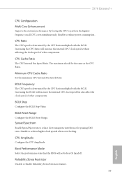
... he CPU speed is determined by the CPU Ratio multiplied with the BCLK. Boot Performance Mode Select the performance state that the BIOS will increase the internal CPU clock speed without afecting the clock speed of other components. Disable to reduce electromagnetic interference for passing ... the internal CPU clock speed but also afect the clock speed of other components. BCLK Reset Range Conigure the BCLK Reset Range. Z170 Extreme7+ CPU Coniguration Multi Core Enhancement Improve the system's performance by the CPU Ratio multiplied with the BCLK. Disable to perform the highest...
... he CPU speed is determined by the CPU Ratio multiplied with the BCLK. Boot Performance Mode Select the performance state that the BIOS will increase the internal CPU clock speed without afecting the clock speed of other components. Disable to reduce electromagnetic interference for passing ... the internal CPU clock speed but also afect the clock speed of other components. BCLK Reset Range Conigure the BCLK Reset Range. Z170 Extreme7+ CPU Coniguration Multi Core Enhancement Improve the system's performance by the CPU Ratio multiplied with the BCLK. Disable to perform the highest...

User Manual
Page 90
he higher the value, the faster the fan speed. Internet Flash - Please setup network coniguration before using this function. DHCP (Auto IP), Auto ASRock Internet Flash downloads and updates the latest UEFI irmware version from our servers for you. Dehumidiier CPU Fan Setting Conigure the speed of the ROM ... computer powers on and enables Dehumidiier ater entering S4/S5 state. Dehumidiier Period Conigure the period of the dehumidifying process before using Internet Flash. *For BIOS backup and recovery purpose, it returns to S4/S5 state.
he higher the value, the faster the fan speed. Internet Flash - Please setup network coniguration before using this function. DHCP (Auto IP), Auto ASRock Internet Flash downloads and updates the latest UEFI irmware version from our servers for you. Dehumidiier CPU Fan Setting Conigure the speed of the ROM ... computer powers on and enables Dehumidiier ater entering S4/S5 state. Dehumidiier Period Conigure the period of the dehumidifying process before using Internet Flash. *For BIOS backup and recovery purpose, it returns to S4/S5 state.


