

User Manual
Page 2
..., or translated in any language, in this documentation may apply, see www.dtsc.ca.gov/hazardouswaste/ perchlorate" ASRock Website: http://www.asrock.com All rights reserved. Products and corporate names appearing in the documentation or product. Copyright Notice: No part ... informational use only and subject to change without intent to the contents of this motherboard contains Perchlorate, a toxic substance controlled in advance. With respect to infringe. ASRock assumes no event shall ASRock, its directors, oicers, employees, or agents be constructed as a commitment by ...
..., or translated in any language, in this documentation may apply, see www.dtsc.ca.gov/hazardouswaste/ perchlorate" ASRock Website: http://www.asrock.com All rights reserved. Products and corporate names appearing in the documentation or product. Copyright Notice: No part ... informational use only and subject to change without intent to the contents of this motherboard contains Perchlorate, a toxic substance controlled in advance. With respect to infringe. ASRock assumes no event shall ASRock, its directors, oicers, employees, or agents be constructed as a commitment by ...
User Manual
Page 4
Contents Chapter 1 Introduction 1 1.1 Package Contents 1 1.2 Speciications 2 1.3 Motherboard Layout 7 1.4 I/O Panel 9 1.5 ASRock Front USB 3.1 Panel (for Z170 Extreme4+ only) 11 Chapter 2 Installation 14 2.1 Installing the CPU 15 2.2 Installing the CPU Fan and Heatsink 18 2.3 Installing Memory Modules (DIMM) 19 2.4 Expansion Slots (PCI Express ...
Contents Chapter 1 Introduction 1 1.1 Package Contents 1 1.2 Speciications 2 1.3 Motherboard Layout 7 1.4 I/O Panel 9 1.5 ASRock Front USB 3.1 Panel (for Z170 Extreme4+ only) 11 Chapter 2 Installation 14 2.1 Installing the CPU 15 2.2 Installing the CPU Fan and Heatsink 18 2.3 Installing Memory Modules (DIMM) 19 2.4 Expansion Slots (PCI Express ...

User Manual
Page 7
... about the model you for Z170 Extreme4+ only) 1 English ASRock website http://www.asrock.com. 1.1 Package Contents • ASRock Z170 Extreme4+ / Z170 Extreme4 Motherboard (ATX Form Factor) • ASRock Z170 Extreme4+ / Z170 Extreme4 Quick Installation Guide • ASRock Z170 Extreme4+ / Z170 Extreme4 Support CD • 4 x Serial ATA (SATA) Data Cables (Optional) • 1 x I/O Panel Shield • 1 x ASRock SLI_Bridge_2S Card • 1 x Screw for M.2 Socket • 1 x ASRock Front USB 3.1 Panel (for Z170 Extreme4+ only) • 4 x Screws for...
... about the model you for Z170 Extreme4+ only) 1 English ASRock website http://www.asrock.com. 1.1 Package Contents • ASRock Z170 Extreme4+ / Z170 Extreme4 Motherboard (ATX Form Factor) • ASRock Z170 Extreme4+ / Z170 Extreme4 Quick Installation Guide • ASRock Z170 Extreme4+ / Z170 Extreme4 Support CD • 4 x Serial ATA (SATA) Data Cables (Optional) • 1 x I/O Panel Shield • 1 x ASRock SLI_Bridge_2S Card • 1 x Screw for M.2 Socket • 1 x ASRock Front USB 3.1 Panel (for Z170 Extreme4+ only) • 4 x Screws for...

User Manual
Page 13
1.3 Motherboard Layout Z170 Extreme4+ / Z170 Extreme4 PS2 Keyboard /Mouse USB 3.0 T: USB1 B: USB2 ATX12V1 CLRC BTN1 CPU_FAN1 CPU_FAN2 DVI1 HDMI1 DISPLAY1 DDR4_A1 (64 bit, 288-pin module) DDR4_A2 (64 bit, 288-pin... M2_1 CT5 CT4 Purity SoundTM 3 PCIE3 CT3 CT2 CT1 Ultra M.2 PCIe Gen3 x4 PCIE4 HD_AUDIO1 1 PCIE5 RoHS COM1 1 PCIE6 TPMS1 1 T B1 1 USB_1_2 1 USB_3_4 1 Intel Z170 CLRMOS1 1 Power Reset BIOS_B1 128Mb BIOS BIOS_B_LED BIOS_A1 128Mb BIOS BIOS_A_LED 1 BIOS_SEL1 CHA_FAN2 SPK_PLED1 Dr. Debug 1 PLED PWRBTN 1 HDLED RESET SATA3_5_4 PANEL1 SATA3_4 SATA3_5 SATA_EXP2...
1.3 Motherboard Layout Z170 Extreme4+ / Z170 Extreme4 PS2 Keyboard /Mouse USB 3.0 T: USB1 B: USB2 ATX12V1 CLRC BTN1 CPU_FAN1 CPU_FAN2 DVI1 HDMI1 DISPLAY1 DDR4_A1 (64 bit, 288-pin module) DDR4_A2 (64 bit, 288-pin... M2_1 CT5 CT4 Purity SoundTM 3 PCIE3 CT3 CT2 CT1 Ultra M.2 PCIe Gen3 x4 PCIE4 HD_AUDIO1 1 PCIE5 RoHS COM1 1 PCIE6 TPMS1 1 T B1 1 USB_1_2 1 USB_3_4 1 Intel Z170 CLRMOS1 1 Power Reset BIOS_B1 128Mb BIOS BIOS_B_LED BIOS_A1 128Mb BIOS BIOS_A_LED 1 BIOS_SEL1 CHA_FAN2 SPK_PLED1 Dr. Debug 1 PLED PWRBTN 1 HDLED RESET SATA3_5_4 PANEL1 SATA3_4 SATA3_5 SATA_EXP2...
User Manual
Page 17
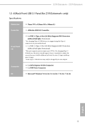
... to 5V/3A. Z170 Extreme4+ / Z170 Extreme4 1.5 ASRock Front USB 3.1 Panel (for Z170 Extreme4+ only) Speciications Dimension • 75mm (W) x 42.8mm (H) x 148mm (L) Controller • ASMedia ASM1142 Controller Front Panel I/O • 1 x USB 3.1 Type-A Port (10 Gb/s) (Supports ESD Protection (ASRock Full Spike Protection)) * For charging Type-A USB devices, we suggest using the Type-A connectors on your motherboard. • 1 x USB 3.1 Type...
... to 5V/3A. Z170 Extreme4+ / Z170 Extreme4 1.5 ASRock Front USB 3.1 Panel (for Z170 Extreme4+ only) Speciications Dimension • 75mm (W) x 42.8mm (H) x 148mm (L) Controller • ASMedia ASM1142 Controller Front Panel I/O • 1 x USB 3.1 Type-A Port (10 Gb/s) (Supports ESD Protection (ASRock Full Spike Protection)) * For charging Type-A USB devices, we suggest using the Type-A connectors on your motherboard. • 1 x USB 3.1 Type...
User Manual
Page 19
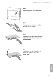
SATA3_4_5 SATA3_A1_A2 SATA3_A3_A4 SATA_EXP0 SATA3_1_3 SATA3_0_2 Step 6 Connect the PSU's SATA Power Cable to the drive bay with screws. USB3_4 USB3_4 13 USB 3.0 USB 3.0 English Z170 Extreme4+ / Z170 Extreme4 Step 5 Screw ASRock Front USB 3.1 Panel to the SATA Power Connector. SATA3_4_5 SATA3_A1_A2 SATA3_A3_A4 SATA_EXP0 SATA3_1_3 SATA3_0_2 Step 8 Connect the other end of the USB Power Cable to the SATA Express Connector on the motherboard. Step 7 Connect the other end of the SATA Express Cable to the USB 2.0 Header on the motherboard.
SATA3_4_5 SATA3_A1_A2 SATA3_A3_A4 SATA_EXP0 SATA3_1_3 SATA3_0_2 Step 6 Connect the PSU's SATA Power Cable to the drive bay with screws. USB3_4 USB3_4 13 USB 3.0 USB 3.0 English Z170 Extreme4+ / Z170 Extreme4 Step 5 Screw ASRock Front USB 3.1 Panel to the SATA Power Connector. SATA3_4_5 SATA3_A1_A2 SATA3_A3_A4 SATA_EXP0 SATA3_1_3 SATA3_0_2 Step 8 Connect the other end of the USB Power Cable to the SATA Express Connector on the motherboard. Step 7 Connect the other end of the SATA Express Cable to the USB 2.0 Header on the motherboard.

User Manual
Page 20
... into it. Also remember to use a grounded wrist strap or touch a safety grounded object before you uninstall any motherboard settings. • Make sure to the chassis, please do not touch the ICs. • Whenever you handle the components. • Hold ... overtighten the screws! Doing so may cause physical injuries and damages to motherboard components. • In order to avoid damage from static electricity to the motherboard's components, NEVER place your chassis to do so may damage the motherboard. 14 English Failure to ensure that comes with the components. •...
... into it. Also remember to use a grounded wrist strap or touch a safety grounded object before you uninstall any motherboard settings. • Make sure to the chassis, please do not touch the ICs. • Whenever you handle the components. • Hold ... overtighten the screws! Doing so may cause physical injuries and damages to motherboard components. • In order to avoid damage from static electricity to the motherboard's components, NEVER place your chassis to do so may damage the motherboard. 14 English Failure to ensure that comes with the components. •...

User Manual
Page 23
Z170 Extreme4+ / Z170 Extreme4 Please save and replace the cover if the processor is removed. he cover must be placed if you wish to return the motherboard for ater service. 17 English
Z170 Extreme4+ / Z170 Extreme4 Please save and replace the cover if the processor is removed. he cover must be placed if you wish to return the motherboard for ater service. 17 English
User Manual
Page 25
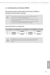
Z170 Extreme4+ / Z170 Extreme4 2.3 Installing Memory Modules (DIMM) his motherboard provides four 288-pin DDR4 (Double Data Rate 4) DIMM slots, and supports Dual Channel Memory Technology. 1. English 19 It is not allowed to install a DDR, ... one or three memory module installed. 3. It is unable to install identical (the same brand, speed, size and chip-type) DDR4 DIMM pairs. 2. otherwise, this motherboard and DIMM may be damaged. For dual channel coniguration, you force the DIMM into a DDR4 slot; It will cause permanent damage to the...
Z170 Extreme4+ / Z170 Extreme4 2.3 Installing Memory Modules (DIMM) his motherboard provides four 288-pin DDR4 (Double Data Rate 4) DIMM slots, and supports Dual Channel Memory Technology. 1. English 19 It is not allowed to install a DDR, ... one or three memory module installed. 3. It is unable to install identical (the same brand, speed, size and chip-type) DDR4 DIMM pairs. 2. otherwise, this motherboard and DIMM may be damaged. For dual channel coniguration, you force the DIMM into a DDR4 slot; It will cause permanent damage to the...

User Manual
Page 27
...used for PCI Express x1 lane width cards. PCIE4 (PCIe 3.0 x16 slot) is unplugged. Z170 Extreme4+ / Z170 Extreme4 2.4 Expansion Slots (PCI Express Slots) here are 6 PCI Express slots on the motherboard. Please read the documentation of the expansion card and make sure that the power supply is ... hree Graphics Cards in 3-Way CrossFireXTM Mode x8 x8 x4 English For a better thermal environment, please connect a chassis fan to the motherboard's chassis fan connector (CHA_FAN1, CHA_FAN2 or CHA_FAN3) when using multiple graphics cards. 21 PCIe slots: PCIE1 (PCIe 3.0 x1 slot) ...
...used for PCI Express x1 lane width cards. PCIE4 (PCIe 3.0 x16 slot) is unplugged. Z170 Extreme4+ / Z170 Extreme4 2.4 Expansion Slots (PCI Express Slots) here are 6 PCI Express slots on the motherboard. Please read the documentation of the expansion card and make sure that the power supply is ... hree Graphics Cards in 3-Way CrossFireXTM Mode x8 x8 x4 English For a better thermal environment, please connect a chassis fan to the motherboard's chassis fan connector (CHA_FAN1, CHA_FAN2 or CHA_FAN3) when using multiple graphics cards. 21 PCIe slots: PCIE1 (PCIe 3.0 x1 slot) ...
User Manual
Page 29
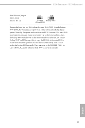
However, if the main BIOS is activated currently. Z170 Extreme4+ / Z170 Extreme4 BIOS Selection Jumper (BIOS_SEL1) (see p.7, No. 12) Default Backup BIOS (Main BIOS) his motherboard has two BIOS onboard, a main BIOS (BIOS_A) and a backup BIOS (BIOS_B), which BIOS is corrupted or damaged, please use "Secure Backup UEFI" in BIOS setup ...
However, if the main BIOS is activated currently. Z170 Extreme4+ / Z170 Extreme4 BIOS Selection Jumper (BIOS_SEL1) (see p.7, No. 12) Default Backup BIOS (Main BIOS) his motherboard has two BIOS onboard, a main BIOS (BIOS_A) and a backup BIOS (BIOS_B), which BIOS is corrupted or damaged, please use "Secure Backup UEFI" in BIOS setup ...

User Manual
Page 30
..., power LED, hard drive activity LED, speaker and etc. Note the positive and negative pins before connecting the cables. RESET (Reset Switch): Connect to the motherboard. he LED is on when the system is in S1/S3 sleep state. A front panel module mainly consists of your chassis front panel module to...
..., power LED, hard drive activity LED, speaker and etc. Note the positive and negative pins before connecting the cables. RESET (Reset Switch): Connect to the motherboard. he LED is on when the system is in S1/S3 sleep state. A front panel module mainly consists of your chassis front panel module to...

User Manual
Page 31
... 6.0 Gb/s data transfer rate. Each USB 2.0 header can support two ports. 25 English Please connect the chassis power LED and the chassis speaker to this motherboard. Z170 Extreme4+ / Z170 Extreme4 Power LED and Speaker Header (7-pin SPK_PLED1) (see p.7, No. 11) Please connect either SATA or PCIe storage devices to these connectors.
... 6.0 Gb/s data transfer rate. Each USB 2.0 header can support two ports. 25 English Please connect the chassis power LED and the chassis speaker to this motherboard. Z170 Extreme4+ / Z170 Extreme4 Power LED and Speaker Header (7-pin SPK_PLED1) (see p.7, No. 11) Please connect either SATA or PCIe storage devices to these connectors.

User Manual
Page 32
... is one header on the chassis must support HDA to the ground pin. High Deinition Audio supports Jack Sensing, but the panel wire on this motherboard. C. Chassis Fan Connectors (4-pin CHA_FAN1) (see p.7, No. 26) (4-pin CHA_FAN2) (see p.7, No. 13) (4-pin CHA_FAN3) (see p.7, No. 8) GND FAN_VOLTAGE CHA_FAN_SPEED FAN_SPEED_CONTROL Please connect fan cables...
... is one header on the chassis must support HDA to the ground pin. High Deinition Audio supports Jack Sensing, but the panel wire on this motherboard. C. Chassis Fan Connectors (4-pin CHA_FAN1) (see p.7, No. 26) (4-pin CHA_FAN2) (see p.7, No. 13) (4-pin CHA_FAN3) (see p.7, No. 8) GND FAN_VOLTAGE CHA_FAN_SPEED FAN_SPEED_CONTROL Please connect fan cables...

User Manual
Page 33
... (Quiet Fan) connector. hunderbolt AIC Connector (5-pin TB1) (see p.7, No. 1) 8 5 his COM1 header supports a serial port module. Z170 Extreme4+ / Z170 Extreme4 CPU Fan Connectors (4-pin CPU_FAN1) (see p.7, No. 3) (4-pin CPU_FAN2) (see p.7, No. 2) FAN_SPEED FAN_VOLTAGE_CONTROL GND FAN_SPEED_CONTROL his motherboard provides a 24-pin ATX power connector. To use a 20-pin ATX power supply, please plug it along...
... (Quiet Fan) connector. hunderbolt AIC Connector (5-pin TB1) (see p.7, No. 1) 8 5 his COM1 header supports a serial port module. Z170 Extreme4+ / Z170 Extreme4 CPU Fan Connectors (4-pin CPU_FAN1) (see p.7, No. 3) (4-pin CPU_FAN2) (see p.7, No. 2) FAN_SPEED FAN_VOLTAGE_CONTROL GND FAN_SPEED_CONTROL his motherboard provides a 24-pin ATX power connector. To use a 20-pin ATX power supply, please plug it along...

User Manual
Page 35
... to quickly turn on /of the system. Power Switch (PWRBTN) (see p.9, No. 16) Clear CMOS Switch allows users to quickly reset the system. Z170 Extreme4+ / Z170 Extreme4 2.7 Smart Switches he motherboard has three smart switches: Power Switch, Reset Switch and Clear CMOS Switch, allowing users to quickly turn on /of the system, reset the system...
... to quickly turn on /of the system. Power Switch (PWRBTN) (see p.9, No. 16) Clear CMOS Switch allows users to quickly reset the system. Z170 Extreme4+ / Z170 Extreme4 2.7 Smart Switches he motherboard has three smart switches: Power Switch, Reset Switch and Clear CMOS Switch, allowing users to quickly turn on /of the system, reset the system...

User Manual
Page 38
... graphics card into PCIE2 slot and the other graphics card to the PCI Express graphics cards. 32 English 2.9 SLITM and Quad SLITM Operation Guide his motherboard supports NVIDIA® SLITM and Quad SLITM (Scalable Link Interface) technology that your power supply unit (PSU) can provide at least the minimum power your...
... graphics card into PCIE2 slot and the other graphics card to the PCI Express graphics cards. 32 English 2.9 SLITM and Quad SLITM Operation Guide his motherboard supports NVIDIA® SLITM and Quad SLITM (Scalable Link Interface) technology that your power supply unit (PSU) can provide at least the minimum power your...

User Manual
Page 41
... CrossFireXTM-Ready Graphics Cards Step 1 Insert one graphics card into PCIE2 slot and the other graphics card to PCIE4 slot. Z170 Extreme4+ / Z170 Extreme4 2.10 CrossFireXTM , 3-Way CrossFireXTM and Quad CrossFireXTM Operation Guide his motherboard supports CrossFireXTM, 3-way CrossFireXTM and Quad CrossFireXTM that are properly seated on the top of the graphics cards. (he CrossFire... graphics cards. 1. You should only use a AMD certiied PSU. It is provided with the graphics card you pair a 12-pipe CrossFireXTM Edition card with this motherboard.
... CrossFireXTM-Ready Graphics Cards Step 1 Insert one graphics card into PCIE2 slot and the other graphics card to PCIE4 slot. Z170 Extreme4+ / Z170 Extreme4 2.10 CrossFireXTM , 3-Way CrossFireXTM and Quad CrossFireXTM Operation Guide his motherboard supports CrossFireXTM, 3-way CrossFireXTM and Quad CrossFireXTM that are properly seated on the top of the graphics cards. (he CrossFire... graphics cards. 1. You should only use a AMD certiied PSU. It is provided with the graphics card you pair a 12-pipe CrossFireXTM Edition card with this motherboard.

User Manual
Page 43
Z170 Extreme4+ / Z170 Extreme4 2.10.2 Installing Three CrossFireXTM-Ready Graphics Cards Step 1 Insert one CrossFire Bridge to connect the graphics cards on PCIE2 and PCIE4 slots, and use the other graphics card to PCIE6 slot. Make sure that is provided with the graphics card you purchase, not bundled with this motherboard. English 37 CrossFire Bridge Step...
Z170 Extreme4+ / Z170 Extreme4 2.10.2 Installing Three CrossFireXTM-Ready Graphics Cards Step 1 Insert one CrossFire Bridge to connect the graphics cards on PCIE2 and PCIE4 slots, and use the other graphics card to PCIE6 slot. Make sure that is provided with the graphics card you purchase, not bundled with this motherboard. English 37 CrossFire Bridge Step...

User Manual
Page 46
... you are going to be aware that the M.2 (NGFF) SSD module only its in one orientation. Step 4 Peel of the yellow protective ilm on the motherboard. Hand tighten the standof into the M.2 slot. Please be used. E D C B A E D C B A C B A E D C B A Step 3 Move the standof based on the module type and length. Step 5 Align and gently...
... you are going to be aware that the M.2 (NGFF) SSD module only its in one orientation. Step 4 Peel of the yellow protective ilm on the motherboard. Hand tighten the standof into the M.2 slot. Please be used. E D C B A E D C B A C B A E D C B A Step 3 Move the standof based on the module type and length. Step 5 Align and gently...

