

User Manual
Page 5
... 3 Software and Utilities Operation 51 3.1 Installing Drivers 51 3.2 Formula Drive 52 3.3 ASRock APP Shop 58 3.3.1 UI Overview 58 3.3.2 Apps 59 3.3.3 BIOS & Drivers 62 3.3.4 Setting 63 3.4 Start8 64 Chapter 4 UEFI SETUP UTILITY 70 4.1 Introduction 70 4.1.1 UEFI Menu Bar 70 4.1.2 Navigation Keys 71 4.2 Main Screen 72 4.3 OC Tweaker Screen 73 4.4 Advanced Screen 83 4.4.1 CPU Coniguration 84
... 3 Software and Utilities Operation 51 3.1 Installing Drivers 51 3.2 Formula Drive 52 3.3 ASRock APP Shop 58 3.3.1 UI Overview 58 3.3.2 Apps 59 3.3.3 BIOS & Drivers 62 3.3.4 Setting 63 3.4 Start8 64 Chapter 4 UEFI SETUP UTILITY 70 4.1 Introduction 70 4.1.1 UEFI Menu Bar 70 4.1.2 Navigation Keys 71 4.2 Main Screen 72 4.3 OC Tweaker Screen 73 4.4 Advanced Screen 83 4.4.1 CPU Coniguration 84
User Manual
Page 7
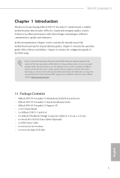
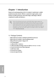
... motherboard speciications and the BIOS sotware might be available on ASRock's website as well. If you require technical support related to quality and endurance. ASRock website http://www.asrock.com. 1.1 Package Contents • ASRock X99 OC Formula/3.1 Motherboard (EATX Form Factor) • ASRock X99 OC Formula/3.1 Quick Installation Guide • ASRock X99 OC Formula/3.1 Support CD • 1 x I/O Panel Shield • 1 x ASRock USB 3.1 Card/A+A • 3 x ASRock Flexible SLI Bridge...
... motherboard speciications and the BIOS sotware might be available on ASRock's website as well. If you require technical support related to quality and endurance. ASRock website http://www.asrock.com. 1.1 Package Contents • ASRock X99 OC Formula/3.1 Motherboard (EATX Form Factor) • ASRock X99 OC Formula/3.1 Quick Installation Guide • ASRock X99 OC Formula/3.1 Support CD • 1 x I/O Panel Shield • 1 x ASRock USB 3.1 Card/A+A • 3 x ASRock Flexible SLI Bridge...
User Manual
Page 11
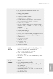
... Legal BIOS with LED • V-ProbeTM: 7-set of onboard voltage measurement points laid • Rapid OC Buttons: +/- X99 OC Formula/3.1 • 1 x 4 pin 12V Power Connector (Hi-Density Power Connector) • 1 x HDD Saver Connector • 1 x PCIe Power Connector • 1 x Front Panel Audio Connector • 1 x hunderbolt AIC Connector • 2 x USB 2.0 Headers (support 4 USB 2.0 ports) (Supports ESD Protection (ASRock...
... Legal BIOS with LED • V-ProbeTM: 7-set of onboard voltage measurement points laid • Rapid OC Buttons: +/- X99 OC Formula/3.1 • 1 x 4 pin 12V Power Connector (Hi-Density Power Connector) • 1 x HDD Saver Connector • 1 x PCIe Power Connector • 1 x Front Panel Audio Connector • 1 x hunderbolt AIC Connector • 2 x USB 2.0 Headers (support 4 USB 2.0 ports) (Supports ESD Protection (ASRock...

User Manual
Page 12
... overclocking. English 6 Due to utilize the memory that there is a certain risk involved with overclocking, including adjusting the setting in the BIOS, applying Untied Overclocking Technology, or using third-party overclocking tools. You can use . Overclocking may be done at your system. We ...(ErP/EuP ready power supply is required) * For detailed product information, please visit our website: http://www.asrock.com Please realize that Windows® cannot use ASRock XFast RAM to limitation, the actual memory size may afect your system's stability, or even cause damage to ...
... overclocking. English 6 Due to utilize the memory that there is a certain risk involved with overclocking, including adjusting the setting in the BIOS, applying Untied Overclocking Technology, or using third-party overclocking tools. You can use . Overclocking may be done at your system. We ...(ErP/EuP ready power supply is required) * For detailed product information, please visit our website: http://www.asrock.com Please realize that Windows® cannot use ASRock XFast RAM to limitation, the actual memory size may afect your system's stability, or even cause damage to ...

User Manual
Page 13
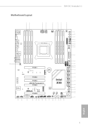
X99 OC Formula/3.1 1.3 Motherboard Layout 12 3 4 5 67 8 USB 2.0 T: USB1 B: USB2 PS2 Keyboard /Mouse DDR4_D2 (64 bit, 288-pin module) DDR4_D1 (64 bit, 288-pin module) ...RoHS SATA3_0_3 MINI_PCIE1 PCIE2 24 SATA3_1_4 PCIE3 Intel 25 X99 OC Formula/3.1 X99 PCIE4 26 SATA3_2_5 SATAE_1 Ultra M.2 PCIe Gen3 x4 ULTRA_M2 Purity SoundTM 2 CT5 HD_AUDIO1 1 T BT1 1 CT4 PCIE_PWR1 CT3 CT2 Super I/O PCIE5 COM1 1 CHA_FAN1 USB5_6 USB3_4 CLRMOS1 1 1 1 1 Super I/O TPMS1 BIOS_A 128Mb BIOS BIOS_A 128Mb BIOS BIOS_A_LED BIOS_A_LED CHA_FAN2 Reset Power 1 PLED1 1 SPEAKER1...
X99 OC Formula/3.1 1.3 Motherboard Layout 12 3 4 5 67 8 USB 2.0 T: USB1 B: USB2 PS2 Keyboard /Mouse DDR4_D2 (64 bit, 288-pin module) DDR4_D1 (64 bit, 288-pin module) ...RoHS SATA3_0_3 MINI_PCIE1 PCIE2 24 SATA3_1_4 PCIE3 Intel 25 X99 OC Formula/3.1 X99 PCIE4 26 SATA3_2_5 SATAE_1 Ultra M.2 PCIe Gen3 x4 ULTRA_M2 Purity SoundTM 2 CT5 HD_AUDIO1 1 T BT1 1 CT4 PCIE_PWR1 CT3 CT2 Super I/O PCIE5 COM1 1 CHA_FAN1 USB5_6 USB3_4 CLRMOS1 1 1 1 1 Super I/O TPMS1 BIOS_A 128Mb BIOS BIOS_A 128Mb BIOS BIOS_A_LED BIOS_A_LED CHA_FAN2 Reset Power 1 PLED1 1 SPEAKER1...

User Manual
Page 14
...288-pin DDR4 DIMM Slots (DDR4_D2, DDR4_C2) 7 2 x 288-pin DDR4 DIMM Slots (DDR4_D1, DDR4_C1) 8 CPU Fan Connector (CPU_FAN2) 9 Rapid OC Button (+) (PLUS) 10 Rapid OC Button (-) (MINUS) 11 Menu Button (MENU) 12 PCIe ON/OFF Switch (SWITCH1) 13 LN2 Mode Switch (LN2MODE) 14 Slow Mode Switch (SLOWMODE...SATA3_0_3) 25 SATA3 Connectors (SATA3_1_4) 26 SATA3 Connectors (SATA3_2_5) 27 SATA Express Connector (SATAE_1) 28 HDD Saver Connector (SATA_PWR_1) 29 BIOS Selection Switch (BIOS_SEL1) 30 Power LED Header (PLED1) 31 Direct Key Button (DIRKEY1) 32 Chassis Speaker Header (SPEAKER1) 33 System Panel Header...
...288-pin DDR4 DIMM Slots (DDR4_D2, DDR4_C2) 7 2 x 288-pin DDR4 DIMM Slots (DDR4_D1, DDR4_C1) 8 CPU Fan Connector (CPU_FAN2) 9 Rapid OC Button (+) (PLUS) 10 Rapid OC Button (-) (MINUS) 11 Menu Button (MENU) 12 PCIe ON/OFF Switch (SWITCH1) 13 LN2 Mode Switch (LN2MODE) 14 Slow Mode Switch (SLOWMODE...SATA3_0_3) 25 SATA3 Connectors (SATA3_1_4) 26 SATA3 Connectors (SATA3_2_5) 27 SATA Express Connector (SATAE_1) 28 HDD Saver Connector (SATA_PWR_1) 29 BIOS Selection Switch (BIOS_SEL1) 30 Power LED Header (PLED1) 31 Direct Key Button (DIRKEY1) 32 Chassis Speaker Header (SPEAKER1) 33 System Panel Header...

User Manual
Page 27
... clear the CMOS when you just inish updating the BIOS, you must boot up the system irst, and then shut it down before you do not clear the CMOS right ater you to clear the data in CMOS. Ater waiting for 5 seconds. X99 OC Formula/3.1 2.5 Jumpers Setup he illustration shows how jumpers are "Short...
... clear the CMOS when you just inish updating the BIOS, you must boot up the system irst, and then shut it down before you do not clear the CMOS right ater you to clear the data in CMOS. Ater waiting for 5 seconds. X99 OC Formula/3.1 2.5 Jumpers Setup he illustration shows how jumpers are "Short...

User Manual
Page 34
... 28 MENU MENU Button allow users to the components and devices. Overclocking may afect your computer and unplug the power supply. + / - Rapid OC But- Menu Button (MENU: see p.7, No. 34) Power Power Switch allows users to quickly toogle among Date/ Time, Temperature, and Voltage ...cause damage to quickly and easily adjust OC frequency in Rapid OC. 2.7 Smart Switches he motherboard has eleven smart switches: Power Switch, Reset Switch, Clear CMOS Switch, Rapid OC Buttons, Menu Button, PCIe ON/OFF Switch, Slow Mode Switch, BIOS Selection Switch, LN2 Mode Switch and...
... 28 MENU MENU Button allow users to the components and devices. Overclocking may afect your computer and unplug the power supply. + / - Rapid OC But- Menu Button (MENU: see p.7, No. 34) Power Power Switch allows users to quickly toogle among Date/ Time, Temperature, and Voltage ...cause damage to quickly and easily adjust OC frequency in Rapid OC. 2.7 Smart Switches he motherboard has eleven smart switches: Power Switch, Reset Switch, Clear CMOS Switch, Rapid OC Buttons, Menu Button, PCIe ON/OFF Switch, Slow Mode Switch, BIOS Selection Switch, LN2 Mode Switch and...

User Manual
Page 35
Make sure that , use "Secure Backup UEFI" in the UEFI Setup Utility to duplicate a working copy of the BIOS iles to the primary BIOS to boot from the motherboard. X99 OC Formula/3.1 1234 OFF PCIe ON/OFF Switch (PCIE_SWITCH) (see p.7, No. 12) 1: PCIE1 2: PCIE2 3: PCIE4 4: PCIE5 ON PCIe ON/OFF Switch allows you to ind out...
Make sure that , use "Secure Backup UEFI" in the UEFI Setup Utility to duplicate a working copy of the BIOS iles to the primary BIOS to boot from the motherboard. X99 OC Formula/3.1 1234 OFF PCIe ON/OFF Switch (PCIE_SWITCH) (see p.7, No. 12) 1: PCIE1 2: PCIE2 3: PCIE4 4: PCIE5 ON PCIe ON/OFF Switch allows you to ind out...

User Manual
Page 62
Multi Thermal Sensor It provides users the temperature of various parts of the motherboard graphically, so that users may precisely keep track and control of the temperature of each parts of BIOS or drivers. 56 English Hardware Monitor Shows the major readings of your system. Live Update Check for newer versions of their motherboard when overclocking. System Browser System Browser shows the overview of your current PC and the devices connected.
Multi Thermal Sensor It provides users the temperature of various parts of the motherboard graphically, so that users may precisely keep track and control of the temperature of each parts of BIOS or drivers. 56 English Hardware Monitor Shows the major readings of your system. Live Update Check for newer versions of their motherboard when overclocking. System Browser System Browser shows the overview of your current PC and the devices connected.

User Manual
Page 68
Step 3 Click Update to update. Step 1 Please check the item information before update. 3.3.3 BIOS & Drivers Installing BIOS or Drivers When the "BIOS & Drivers" tab is selected, you want to start the update process. 62 English Click to select one or more details. Please update them all soon. Click on Step 2 to see more items you will see a list of recommended or critical updates for the BIOS or drivers.
Step 3 Click Update to update. Step 1 Please check the item information before update. 3.3.3 BIOS & Drivers Installing BIOS or Drivers When the "BIOS & Drivers" tab is selected, you want to start the update process. 62 English Click to select one or more details. Please update them all soon. Click on Step 2 to see more items you will see a list of recommended or critical updates for the BIOS or drivers.

User Manual
Page 78
4.2 Main Screen When you enter the UEFI SETUP UTILITY, the Main screen will appear and display the system overview. My Favorite Display your collection of BIOS items. Press F5 to add/remove your favorite items. 72 English
4.2 Main Screen When you enter the UEFI SETUP UTILITY, the Main screen will appear and display the system overview. My Favorite Display your collection of BIOS items. Press F5 to add/remove your favorite items. 72 English

User Manual
Page 98
... or disable all the USB ports. Select UEFI Setup Only to disable legacy USB support. If you encounter USB compatibility issues it is disabled in BIOS). Set [Auto] to automatically enable the USB 3.0 driver ater entering the OS (USB 3.0 is recommended to support USB devices under the UEFI ...Support for USB 2.0 devices. Intel USB 3.0 Mode Select Intel® USB 3.0 controller mode. If you encounter USB compatibility issues it is enabled in BIOS). Set [Enabled] to keep the USB 3.0 driver enabled ater rebooting (USB 3.0 is recommended to disable the USB 3.0 ports.
... or disable all the USB ports. Select UEFI Setup Only to disable legacy USB support. If you encounter USB compatibility issues it is disabled in BIOS). Set [Auto] to automatically enable the USB 3.0 driver ater entering the OS (USB 3.0 is recommended to support USB devices under the UEFI ...Support for USB 2.0 devices. Intel USB 3.0 Mode Select Intel® USB 3.0 controller mode. If you encounter USB compatibility issues it is enabled in BIOS). Set [Enabled] to keep the USB 3.0 driver enabled ater rebooting (USB 3.0 is recommended to disable the USB 3.0 ports.
User Manual
Page 103
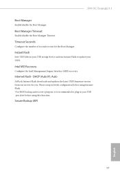
X99 OC Formula/3.1 Boot Manager Enable/disable the Boot Manager. Please setup network coniguration before using Internet Flash. *For BIOS backup and recovery purpose, it is recommended to plug in your USB storage device and run Instant Flash to wait for you. DHCP (Auto IP), Auto ASRock Internet Flash downloads and updates the latest UEFI irmware...
X99 OC Formula/3.1 Boot Manager Enable/disable the Boot Manager. Please setup network coniguration before using Internet Flash. *For BIOS backup and recovery purpose, it is recommended to plug in your USB storage device and run Instant Flash to wait for you. DHCP (Auto IP), Auto ASRock Internet Flash downloads and updates the latest UEFI irmware...
Quick Installation Guide
Page 3
Motherboard Layout 12 X99 OC Formula/3.1 3 4 5 67 8 USB 2.0 T: USB1 B: USB2 PS2 Keyboard /Mouse DDR4_D2 (64 bit, 288-pin module) DDR4_D1 (64 bit, 288-pin module) DDR4_C2 (64 bit,...23 SATA3_0_3 MINI_PCIE1 PCIE2 24 SATA3_1_4 PCIE3 Intel 25 X99 OC Formula/3.1 X99 PCIE4 26 SATA3_2_5 SATAE_1 Ultra M.2 PCIe Gen3 x4 ULTRA_M2 Purity SoundTM 2 CT5 HD_AUDIO1 1 T BT1 1 CT4 PCIE_PWR1 CT3 CT2 Super I/O PCIE5 COM1 1 CHA_FAN1 USB5_6 USB3_4 CLRMOS1 1 1 1 1 Super I/O TPMS1 BIOS_A 128Mb BIOS BIOS_A 128Mb BIOS BIOS_A_LED BIOS_A_LED CHA_FAN2 Reset Power 1 PLED1 1 ...
Motherboard Layout 12 X99 OC Formula/3.1 3 4 5 67 8 USB 2.0 T: USB1 B: USB2 PS2 Keyboard /Mouse DDR4_D2 (64 bit, 288-pin module) DDR4_D1 (64 bit, 288-pin module) DDR4_C2 (64 bit,...23 SATA3_0_3 MINI_PCIE1 PCIE2 24 SATA3_1_4 PCIE3 Intel 25 X99 OC Formula/3.1 X99 PCIE4 26 SATA3_2_5 SATAE_1 Ultra M.2 PCIe Gen3 x4 ULTRA_M2 Purity SoundTM 2 CT5 HD_AUDIO1 1 T BT1 1 CT4 PCIE_PWR1 CT3 CT2 Super I/O PCIE5 COM1 1 CHA_FAN1 USB5_6 USB3_4 CLRMOS1 1 1 1 1 Super I/O TPMS1 BIOS_A 128Mb BIOS BIOS_A 128Mb BIOS BIOS_A_LED BIOS_A_LED CHA_FAN2 Reset Power 1 PLED1 1 ...

Quick Installation Guide
Page 4
...288-pin DDR4 DIMM Slots (DDR4_D2, DDR4_C2) 7 2 x 288-pin DDR4 DIMM Slots (DDR4_D1, DDR4_C1) 8 CPU Fan Connector (CPU_FAN2) 9 Rapid OC Button (+) (PLUS) 10 Rapid OC Button (-) (MINUS) 11 Menu Button (MENU) 12 PCIe ON/OFF Switch (SWITCH1) 13 LN2 Mode Switch (LN2MODE) 14 Slow Mode Switch (SLOWMODE... (SATA3_0_3) 25 SATA3 Connectors (SATA3_1_4) 26 SATA3 Connectors (SATA3_2_5) 27 SATA Express Connector (SATAE_1) 28 HDD Saver Connector (SATA_PWR_1) 29 BIOS Selection Switch (BIOS_SEL1) 30 Power LED Header (PLED1) 31 Direct Key Button (DIRKEY1) 32 Chassis Speaker Header (SPEAKER1) 33 System Panel ...
...288-pin DDR4 DIMM Slots (DDR4_D2, DDR4_C2) 7 2 x 288-pin DDR4 DIMM Slots (DDR4_D1, DDR4_C1) 8 CPU Fan Connector (CPU_FAN2) 9 Rapid OC Button (+) (PLUS) 10 Rapid OC Button (-) (MINUS) 11 Menu Button (MENU) 12 PCIe ON/OFF Switch (SWITCH1) 13 LN2 Mode Switch (LN2MODE) 14 Slow Mode Switch (SLOWMODE... (SATA3_0_3) 25 SATA3 Connectors (SATA3_1_4) 26 SATA3 Connectors (SATA3_2_5) 27 SATA Express Connector (SATAE_1) 28 HDD Saver Connector (SATA_PWR_1) 29 BIOS Selection Switch (BIOS_SEL1) 30 Power LED Header (PLED1) 31 Direct Key Button (DIRKEY1) 32 Chassis Speaker Header (SPEAKER1) 33 System Panel ...
Quick Installation Guide
Page 8
... motherboard speciications and the BIOS sotware might be updated, the content of this documentation will be subject to change without further notice. ASRock website http://www.asrock.com. 1.1 Package Contents • ASRock X99 OC Formula/3.1 Motherboard (EATX Form Factor) • ASRock X99 OC Formula/3.1 Quick Installation Guide • ASRock X99 OC Formula/3.1 Support CD • 1 x I/O Panel Shield • 1 x ASRock USB 3.1 Card/A+A • 3 x ASRock Flexible SLI Bridge Connector...
... motherboard speciications and the BIOS sotware might be updated, the content of this documentation will be subject to change without further notice. ASRock website http://www.asrock.com. 1.1 Package Contents • ASRock X99 OC Formula/3.1 Motherboard (EATX Form Factor) • ASRock X99 OC Formula/3.1 Quick Installation Guide • ASRock X99 OC Formula/3.1 Support CD • 1 x I/O Panel Shield • 1 x ASRock USB 3.1 Card/A+A • 3 x ASRock Flexible SLI Bridge Connector...

Quick Installation Guide
Page 12
... USB 3.0 ports) (ASMedia ASM1074 hub) (Supports ESD Protection (ASRock Full Spike Protection)) • 1 x Dr. Debug with LED • 1 x Power Switch with LED • 1 x Reset Switch with multilingual GUI support (1 x Main BIOS and 1 x Backup BIOS) • Supports Secure Backup UEFI Technology • ACPI 1.1 ... buttons to adjust OC frequency • 1 x Menu Button • 1 x PCIe ON/OFF Switch • 1 x Slow Mode Switch • 1 x LN2 Mode Switch • 1 x BIOS Selection Switch • 1 x Direct Key Button BIOS Feature • 2 x 128Mb AMI UEFI Legal BIOS with LED •...
... USB 3.0 ports) (ASMedia ASM1074 hub) (Supports ESD Protection (ASRock Full Spike Protection)) • 1 x Dr. Debug with LED • 1 x Power Switch with LED • 1 x Reset Switch with multilingual GUI support (1 x Main BIOS and 1 x Backup BIOS) • Supports Secure Backup UEFI Technology • ACPI 1.1 ... buttons to adjust OC frequency • 1 x Menu Button • 1 x PCIe ON/OFF Switch • 1 x Slow Mode Switch • 1 x LN2 Mode Switch • 1 x BIOS Selection Switch • 1 x Direct Key Button BIOS Feature • 2 x 128Mb AMI UEFI Legal BIOS with LED •...

Quick Installation Guide
Page 13
...that there is a certain risk involved with overclocking, including adjusting the setting in the BIOS, applying Untied Overclocking Technology, or using third-party overclocking tools. We are not ... for possible damage caused by overclocking. Due to limitation, the actual memory size may afect your own risk and expense. X99 OC Formula/3.1 OS Certiications • Microsot® Windows® 8.1 32-bit / 8.1 64-bit / 8 32-bit /... visit our website: http://www.asrock.com Please realize that Windows® cannot use ASRock XFast RAM to the components and devices of your system.
...that there is a certain risk involved with overclocking, including adjusting the setting in the BIOS, applying Untied Overclocking Technology, or using third-party overclocking tools. We are not ... for possible damage caused by overclocking. Due to limitation, the actual memory size may afect your own risk and expense. X99 OC Formula/3.1 OS Certiications • Microsot® Windows® 8.1 32-bit / 8.1 64-bit / 8 32-bit /... visit our website: http://www.asrock.com Please realize that Windows® cannot use ASRock XFast RAM to the components and devices of your system.

Quick Installation Guide
Page 23
... clear-CMOS action. Please be noted that the password, date, time, and user default proile will be cleared only if the CMOS battery is "Short". X99 OC Formula/3.1 2.5 Jumpers Setup he illustration shows how jumpers are "Short" when a jumper cap is placed on the pins, the jumper is "Open". To clear and ...reset the system parameters to clear the data in CMOS. If you update the BIOS. English 21 If no jumper cap is placed on these 2 pins. Ater waiting for 5 seconds. When the jumper cap is placed on CLRCMOS1 for ...
... clear-CMOS action. Please be noted that the password, date, time, and user default proile will be cleared only if the CMOS battery is "Short". X99 OC Formula/3.1 2.5 Jumpers Setup he illustration shows how jumpers are "Short" when a jumper cap is placed on the pins, the jumper is "Open". To clear and ...reset the system parameters to clear the data in CMOS. If you update the BIOS. English 21 If no jumper cap is placed on these 2 pins. Ater waiting for 5 seconds. When the jumper cap is placed on CLRCMOS1 for ...


