

User Manual
Page 4
... Motherboard Layout 7 1.4 I/O Panel 10 Chapter 2 Installation 12 2.1 Installing the CPU 13 2.2 Installing the CPU Fan and Heatsink 16 2.3 Installation of Memory Modules (DIMM) 17 2.4 Expansion Slots (PCI Express Slots) 19 2.5 Jumpers Setup 21 2.6 Onboard Headers and Connectors 22 2.7 Smart Switches 28 2.8 Dr. Debug 31 2.9 Post Status Checker 33 2.10 SLITM , 3-Way SLITM , 4-Way SLITM and Quad SLITM Operation Guide 34 2.10.1 Installing Two SLITM-Ready Graphics Cards 34 2.10.2 Installing Three SLITM-Ready Graphics Cards 36 2.10.3 Installing Four SLITM-Ready Graphics...
... Motherboard Layout 7 1.4 I/O Panel 10 Chapter 2 Installation 12 2.1 Installing the CPU 13 2.2 Installing the CPU Fan and Heatsink 16 2.3 Installation of Memory Modules (DIMM) 17 2.4 Expansion Slots (PCI Express Slots) 19 2.5 Jumpers Setup 21 2.6 Onboard Headers and Connectors 22 2.7 Smart Switches 28 2.8 Dr. Debug 31 2.9 Post Status Checker 33 2.10 SLITM , 3-Way SLITM , 4-Way SLITM and Quad SLITM Operation Guide 34 2.10.1 Installing Two SLITM-Ready Graphics Cards 34 2.10.2 Installing Three SLITM-Ready Graphics Cards 36 2.10.3 Installing Four SLITM-Ready Graphics...
User Manual
Page 7
... utilities. In case any modiications of this documentation, Chapter 1 and 2 contains the introduction of the BIOS setup. Because the motherboard speciications and the BIOS sotware might be subject to change without further notice. X99 OC Formula/3.1 Chapter 1 Introduction hank you for mini-PCIe Slot 1 English Chapter 4 contains the coniguration guide of the motherboard and step-by-step installation guides. You may ind the latest VGA cards and CPU support list on ASRock...
... utilities. In case any modiications of this documentation, Chapter 1 and 2 contains the introduction of the BIOS setup. Because the motherboard speciications and the BIOS sotware might be subject to change without further notice. X99 OC Formula/3.1 Chapter 1 Introduction hank you for mini-PCIe Slot 1 English Chapter 4 contains the coniguration guide of the motherboard and step-by-step installation guides. You may ind the latest VGA cards and CPU support list on ASRock...

User Manual
Page 10
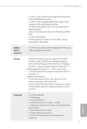
... LAN Ports with LED (ACT/LINK LED and SPEED LED) • 1 x Clear CMOS Switch • HD Audio Jacks: Rear Speaker / Central / Bass / Line in / Front Speaker / Microphone ASRock USB 3.1 Card/A+A • 2 x USB 3.1 Type-A Ports (10 Gb/s) (Supports ESD Protection (ASRock Full Spike Protection)) Storage • 10 x SATA3 6.0 Gb/s Connectors, support RAID (RAID 0, RAID 1, RAID 5, RAID 10 and Intel Rapid Storage 13), NCQ, AHCI, Hot Plug and ASRock HDD Saver Technology (S_SATA3_3 connector is shared with M.2 Socket (M2_1)) * RAID is supported on SATA3_0 ~ SATA3_5 ports only. • 1 x SATA...
... LAN Ports with LED (ACT/LINK LED and SPEED LED) • 1 x Clear CMOS Switch • HD Audio Jacks: Rear Speaker / Central / Bass / Line in / Front Speaker / Microphone ASRock USB 3.1 Card/A+A • 2 x USB 3.1 Type-A Ports (10 Gb/s) (Supports ESD Protection (ASRock Full Spike Protection)) Storage • 10 x SATA3 6.0 Gb/s Connectors, support RAID (RAID 0, RAID 1, RAID 5, RAID 10 and Intel Rapid Storage 13), NCQ, AHCI, Hot Plug and ASRock HDD Saver Technology (S_SATA3_3 connector is shared with M.2 Socket (M2_1)) * RAID is supported on SATA3_0 ~ SATA3_5 ports only. • 1 x SATA...
User Manual
Page 11
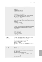
... OC frequency • 1 x Menu Button • 1 x PCIe ON/OFF Switch • 1 x Slow Mode Switch • 1 x LN2 Mode Switch • 1 x BIOS Selection Switch • 1 x Direct Key Button BIOS Feature • 2 x 128Mb AMI UEFI Legal BIOS with LED • V-ProbeTM: 7-set of onboard voltage measurement points laid • Rapid OC Buttons: +/- X99 OC Formula/3.1 • 1 x 4 pin 12V Power Connector (Hi-Density Power Connector) • 1 x HDD Saver Connector • 1 x PCIe Power Connector • 1 x Front Panel Audio Connector • 1 x hunderbolt AIC Connector • 2 x USB...
... OC frequency • 1 x Menu Button • 1 x PCIe ON/OFF Switch • 1 x Slow Mode Switch • 1 x LN2 Mode Switch • 1 x BIOS Selection Switch • 1 x Direct Key Button BIOS Feature • 2 x 128Mb AMI UEFI Legal BIOS with LED • V-ProbeTM: 7-set of onboard voltage measurement points laid • Rapid OC Buttons: +/- X99 OC Formula/3.1 • 1 x 4 pin 12V Power Connector (Hi-Density Power Connector) • 1 x HDD Saver Connector • 1 x PCIe Power Connector • 1 x Front Panel Audio Connector • 1 x hunderbolt AIC Connector • 2 x USB...

User Manual
Page 14
...) 16 Post Status Checker (PSC) 17 ATX Power Connector (ATXPWR1) 18 USB 3.0 Header (USB3_7_8) 19 Vertical Type A USB 3.0 (USB3_11) 20 Chassis Fan Connector (CHA_FAN3) 21 USB 3.0 Header (USB3_9_10) 22 SATA3 Connectors (S_SATA3_0_1) 23 SATA3 Connectors (S_SATA3_2_3) 24 SATA3 Connectors (SATA3_0_3) 25 SATA3 Connectors (SATA3_1_4) 26 SATA3 Connectors (SATA3_2_5) 27 SATA Express Connector (SATAE_1) 28 HDD Saver Connector (SATA_PWR_1) 29 BIOS Selection Switch (BIOS_SEL1) 30 Power LED Header (PLED1) 31 Direct Key Button (DIRKEY1) 32 Chassis Speaker Header (SPEAKER1) 33 System Panel Header (PANEL1...
...) 16 Post Status Checker (PSC) 17 ATX Power Connector (ATXPWR1) 18 USB 3.0 Header (USB3_7_8) 19 Vertical Type A USB 3.0 (USB3_11) 20 Chassis Fan Connector (CHA_FAN3) 21 USB 3.0 Header (USB3_9_10) 22 SATA3 Connectors (S_SATA3_0_1) 23 SATA3 Connectors (S_SATA3_2_3) 24 SATA3 Connectors (SATA3_0_3) 25 SATA3 Connectors (SATA3_1_4) 26 SATA3 Connectors (SATA3_2_5) 27 SATA Express Connector (SATAE_1) 28 HDD Saver Connector (SATA_PWR_1) 29 BIOS Selection Switch (BIOS_SEL1) 30 Power LED Header (PLED1) 31 Direct Key Button (DIRKEY1) 32 Chassis Speaker Header (SPEAKER1) 33 System Panel Header (PANEL1...

User Manual
Page 32
... header supports a serial port module. GND +12V DETECT 1 Please connect a 4 pin molex power cable to this connector via the GPIO cable. *Please install the hunderbolt™ AIC card to this connector when more than three PCI Express cards are installed. English 26 Please connect a hunderbolt™ add-in card (AIC) to PCIE3 (default slot). RRXD1 DDTR#1 DDSR#1 CCTS#1 1 RRI#1 RRTS#1 GND TTXD1 DDCD#1 his motherboard provides an 8-pin ATX 12V power connector and 4 1 a 4-pin ATX 12V power connector. Please connect the HDD...
... header supports a serial port module. GND +12V DETECT 1 Please connect a 4 pin molex power cable to this connector via the GPIO cable. *Please install the hunderbolt™ AIC card to this connector when more than three PCI Express cards are installed. English 26 Please connect a hunderbolt™ add-in card (AIC) to PCIE3 (default slot). RRXD1 DDTR#1 DDSR#1 CCTS#1 1 RRI#1 RRTS#1 GND TTXD1 DDCD#1 his motherboard provides an 8-pin ATX 12V power connector and 4 1 a 4-pin ATX 12V power connector. Please connect the HDD...
User Manual
Page 37
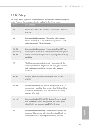
... slots. Please re-install PCI-E devices or try using another VGA card. Please re-install IDE and SATA devices. If the problem still exists, please install only one memory module or try installing them in other memory modules. X99 OC Formula/3.1 2.8 Dr. Debug Dr. Debug is installed correctly and then clear CMOS. 0d Problem related to memory. Code Description 00 Please check if the CPU is used to IDE or SATA devices. If the problem still exists, please remove all SATA devices. If the problem...
... slots. Please re-install PCI-E devices or try using another VGA card. Please re-install IDE and SATA devices. If the problem still exists, please install only one memory module or try installing them in other memory modules. X99 OC Formula/3.1 2.8 Dr. Debug Dr. Debug is installed correctly and then clear CMOS. 0d Problem related to memory. Code Description 00 Please check if the CPU is used to IDE or SATA devices. If the problem still exists, please remove all SATA devices. If the problem...

User Manual
Page 47
... to enable CrossFireXTM. Please refer to four identical PCI Express x16 graphics cards. X99 OC Formula/3.1 2.11 CrossFireXTM, 3-Way CrossFireXTM , 4-Way CrossFireXTM and Quad CrossFireXTM Operation Guide his motherboard supports CrossFireXTM, 3-way CrossFireXTM, 4-way CrossFireXTM and Quad CrossFireXTM that allows you to install up to the AMD's website for details. 4. Download the drivers from the AMD's website: www.amd.com 3. If you install CPU with a 16-pipe card, both cards will...
... to enable CrossFireXTM. Please refer to four identical PCI Express x16 graphics cards. X99 OC Formula/3.1 2.11 CrossFireXTM, 3-Way CrossFireXTM , 4-Way CrossFireXTM and Quad CrossFireXTM Operation Guide his motherboard supports CrossFireXTM, 3-way CrossFireXTM, 4-way CrossFireXTM and Quad CrossFireXTM that allows you to install up to the AMD's website for details. 4. Download the drivers from the AMD's website: www.amd.com 3. If you install CPU with a 16-pipe card, both cards will...

User Manual
Page 50
... boot into OS. Step 3 Install the required drivers and CATALYST Control Center then restart your system. Please check AMD's website for AMD driver updates. We recommend using this utility to uninstall any VGA drivers installed in the Windows® system tray. Step 5 In the let pane, click Performance and then AMD CrossFireXTM. English 44 Select the GPU number according to installation. 2.11.4 Driver Installation and Setup Step 1 Power on your graphics card...
... boot into OS. Step 3 Install the required drivers and CATALYST Control Center then restart your system. Please check AMD's website for AMD driver updates. We recommend using this utility to uninstall any VGA drivers installed in the Windows® system tray. Step 5 In the let pane, click Performance and then AMD CrossFireXTM. English 44 Select the GPU number according to installation. 2.11.4 Driver Installation and Setup Step 1 Power on your graphics card...

User Manual
Page 57
.... X99 OC Formula/3.1 Chapter 3 Software and Utilities Operation 3.1 Installing Drivers he Utilities Menu shows the application sotware that enhance the motherboard's features. Running The Support CD To begin using the support CD, insert the CD into your system will be auto-detected and listed on the ile "ASRSETUP.EXE" in your computer. Please click Install All or follow the installation wizard to install those required drivers. To improve Windows 7 compatibility, please download...
.... X99 OC Formula/3.1 Chapter 3 Software and Utilities Operation 3.1 Installing Drivers he Utilities Menu shows the application sotware that enhance the motherboard's features. Running The Support CD To begin using the support CD, insert the CD into your system will be auto-detected and listed on the ile "ASRSETUP.EXE" in your computer. Please click Install All or follow the installation wizard to install those required drivers. To improve Windows 7 compatibility, please download...
User Manual
Page 63
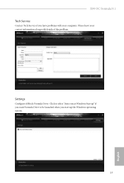
X99 OC Formula/3.1 Tech Service Contact Tech Service if you start up the Windows operating system. 57 English Please leave your contact information along with your computer. Click to select "Auto run at Windows Startup" if you want Formula Drive to be launched when you have problems with details of the problem. Settings Conigure ASRock Formula Drive.
X99 OC Formula/3.1 Tech Service Contact Tech Service if you start up the Windows operating system. 57 English Please leave your contact information along with your computer. Click to select "Auto run at Windows Startup" if you want Formula Drive to be launched when you have problems with details of the problem. Settings Conigure ASRock Formula Drive.

User Manual
Page 98
... (USB 3.0 is recommended to support USB devices under the UEFI setup and Windows/Linux operating systems only. 92 English Set [Disabled] to use USB devices under Windows® 7). Legacy USB 3.0 Support Enable or disable Legacy OS Support for USB 2.0 devices. Legacy USB Support Enable or disable Legacy OS Support for USB 3.0 devices. 4.4.6 USB Coniguration USB Controller Enable or disable all the USB ports. If you encounter USB compatibility issues it is enabled in BIOS). Set [Smart Auto] to keep the USB 3.0 driver enabled (Must install driver to disable the USB 3.0 ports.
... (USB 3.0 is recommended to support USB devices under the UEFI setup and Windows/Linux operating systems only. 92 English Set [Disabled] to use USB devices under Windows® 7). Legacy USB 3.0 Support Enable or disable Legacy OS Support for USB 2.0 devices. Legacy USB Support Enable or disable Legacy OS Support for USB 3.0 devices. 4.4.6 USB Coniguration USB Controller Enable or disable all the USB ports. If you encounter USB compatibility issues it is enabled in BIOS). Set [Smart Auto] to keep the USB 3.0 driver enabled (Must install driver to disable the USB 3.0 ports.

User Manual
Page 102
.... You can start installing the operating system in the UEFI that don't have an optical disk drive to install the drivers from the support CD to your USB storage device. UEFI Tech Service Contact ASRock Tech Service if you are having trouble with your SATA Power connection. Easy Driver Installer For users that installs the LAN driver to use this tool. 96 English Boot Manager Boot Manager is recommended to proceed the re-detection for the dual OS platform...
.... You can start installing the operating system in the UEFI that don't have an optical disk drive to install the drivers from the support CD to your USB storage device. UEFI Tech Service Contact ASRock Tech Service if you are having trouble with your SATA Power connection. Easy Driver Installer For users that installs the LAN driver to use this tool. 96 English Boot Manager Boot Manager is recommended to proceed the re-detection for the dual OS platform...

User Manual
Page 104
Network Coniguration Use this to save your settings as user default. Load User Default Load previously saved user defaults. 98 English Save User Default Type a proile name and press enter to conigure internet connection settings for Internet Flash. Internet Setting Enable or disable sound efects in the setup utility. UEFI Download Server Select a server to the secondary lash ROM. Whenever one of the ROM images are outdated or corrupted, switch to the other lash ROM and execute Secure Backup UEFI to duplicate the current working ROM image to download the UEFI irmware.
Network Coniguration Use this to save your settings as user default. Load User Default Load previously saved user defaults. 98 English Save User Default Type a proile name and press enter to conigure internet connection settings for Internet Flash. Internet Setting Enable or disable sound efects in the setup utility. UEFI Download Server Select a server to the secondary lash ROM. Whenever one of the ROM images are outdated or corrupted, switch to the other lash ROM and execute Secure Backup UEFI to duplicate the current working ROM image to download the UEFI irmware.

Quick Installation Guide
Page 4
...) 16 Post Status Checker (PSC) 17 ATX Power Connector (ATXPWR1) 18 USB 3.0 Header (USB3_7_8) 19 Vertical Type A USB 3.0 (USB3_11) 20 Chassis Fan Connector (CHA_FAN3) 21 USB 3.0 Header (USB3_9_10) 22 SATA3 Connectors (S_SATA3_0_1) 23 SATA3 Connectors (S_SATA3_2_3) 24 SATA3 Connectors (SATA3_0_3) 25 SATA3 Connectors (SATA3_1_4) 26 SATA3 Connectors (SATA3_2_5) 27 SATA Express Connector (SATAE_1) 28 HDD Saver Connector (SATA_PWR_1) 29 BIOS Selection Switch (BIOS_SEL1) 30 Power LED Header (PLED1) 31 Direct Key Button (DIRKEY1) 32 Chassis Speaker Header (SPEAKER1) 33 System Panel Header (PANEL1...
...) 16 Post Status Checker (PSC) 17 ATX Power Connector (ATXPWR1) 18 USB 3.0 Header (USB3_7_8) 19 Vertical Type A USB 3.0 (USB3_11) 20 Chassis Fan Connector (CHA_FAN3) 21 USB 3.0 Header (USB3_9_10) 22 SATA3 Connectors (S_SATA3_0_1) 23 SATA3 Connectors (S_SATA3_2_3) 24 SATA3 Connectors (SATA3_0_3) 25 SATA3 Connectors (SATA3_1_4) 26 SATA3 Connectors (SATA3_2_5) 27 SATA Express Connector (SATAE_1) 28 HDD Saver Connector (SATA_PWR_1) 29 BIOS Selection Switch (BIOS_SEL1) 30 Power LED Header (PLED1) 31 Direct Key Button (DIRKEY1) 32 Chassis Speaker Header (SPEAKER1) 33 System Panel Header (PANEL1...
Quick Installation Guide
Page 11
... LAN Ports with LED (ACT/LINK LED and SPEED LED) • 1 x Clear CMOS Switch • HD Audio Jacks: Rear Speaker / Central / Bass / Line in / Front Speaker / Microphone ASRock USB 3.1 Card/A+A • 2 x USB 3.1 Type-A Ports (10 Gb/s) (Supports ESD Protection (ASRock Full Spike Protection)) Storage • 10 x SATA3 6.0 Gb/s Connectors, support RAID (RAID 0, RAID 1, RAID 5, RAID 10 and Intel Rapid Storage 13), NCQ, AHCI, Hot Plug and ASRock HDD Saver Technology (S_SATA3_3 connector is shared with M.2 Socket (M2_1)) * RAID is supported on SATA3_0 ~ SATA3_5 ports only. • 1 x SATA...
... LAN Ports with LED (ACT/LINK LED and SPEED LED) • 1 x Clear CMOS Switch • HD Audio Jacks: Rear Speaker / Central / Bass / Line in / Front Speaker / Microphone ASRock USB 3.1 Card/A+A • 2 x USB 3.1 Type-A Ports (10 Gb/s) (Supports ESD Protection (ASRock Full Spike Protection)) Storage • 10 x SATA3 6.0 Gb/s Connectors, support RAID (RAID 0, RAID 1, RAID 5, RAID 10 and Intel Rapid Storage 13), NCQ, AHCI, Hot Plug and ASRock HDD Saver Technology (S_SATA3_3 connector is shared with M.2 Socket (M2_1)) * RAID is supported on SATA3_0 ~ SATA3_5 ports only. • 1 x SATA...

Quick Installation Guide
Page 12
...x USB 3.0 Headers (Support 4 USB 3.0 ports) (ASMedia ASM1074 hub) (Supports ESD Protection (ASRock Full Spike Protection)) • 1 x Dr. Debug with LED • 1 x Power Switch with LED • 1 x Reset Switch with multilingual GUI support (1 x Main BIOS and 1 x Backup BIOS) • Supports Secure Backup UEFI Technology • ACPI 1.1 Compliant wake up events • SMBIOS 2.3.1 Support • CPU, DRAM, PCH 1.05V, PCH 1.5V, VPPM Voltage Multi- buttons to adjust OC frequency • 1 x Menu Button • 1 x PCIe ON/OFF Switch • 1 x Slow Mode Switch • 1 x LN2 Mode Switch...
...x USB 3.0 Headers (Support 4 USB 3.0 ports) (ASMedia ASM1074 hub) (Supports ESD Protection (ASRock Full Spike Protection)) • 1 x Dr. Debug with LED • 1 x Power Switch with LED • 1 x Reset Switch with multilingual GUI support (1 x Main BIOS and 1 x Backup BIOS) • Supports Secure Backup UEFI Technology • ACPI 1.1 Compliant wake up events • SMBIOS 2.3.1 Support • CPU, DRAM, PCH 1.05V, PCH 1.5V, VPPM Voltage Multi- buttons to adjust OC frequency • 1 x Menu Button • 1 x PCIe ON/OFF Switch • 1 x Slow Mode Switch • 1 x LN2 Mode Switch...

Quick Installation Guide
Page 28
... supply, please plug it along Pin 1 and Pin 5. *he 4-pin ATX 12V power connector is used to supply additional power to PCIE3 (default slot). RRXD1 DDTR#1 DDSR#1 CCTS#1 1 RRI#1 RRTS#1 GND TTXD1 DDCD#1 his motherboard provides an 8-pin ATX 12V power connector and 4 1 a 4-pin ATX 12V power connector. ATX 12V Power Connectors (8-pin ATX12V1) (see p.1, No. 3) (4-pin ATX12V2) (see p.1, No. 4) PCIe Power Connector (4-pin PCIE_PWR1) (see p.1, No. 43) HDD Saver Connector (4-pin SATA_PWR_1) (see p.1, No. 28) hunderbolt AIC Connector (5-pin TBT1) (see p.1, No. 44) Serial Port Header (9-pin...
... supply, please plug it along Pin 1 and Pin 5. *he 4-pin ATX 12V power connector is used to supply additional power to PCIE3 (default slot). RRXD1 DDTR#1 DDSR#1 CCTS#1 1 RRI#1 RRTS#1 GND TTXD1 DDCD#1 his motherboard provides an 8-pin ATX 12V power connector and 4 1 a 4-pin ATX 12V power connector. ATX 12V Power Connectors (8-pin ATX12V1) (see p.1, No. 3) (4-pin ATX12V2) (see p.1, No. 4) PCIe Power Connector (4-pin PCIE_PWR1) (see p.1, No. 43) HDD Saver Connector (4-pin SATA_PWR_1) (see p.1, No. 28) hunderbolt AIC Connector (5-pin TBT1) (see p.1, No. 44) Serial Port Header (9-pin...

Quick Installation Guide
Page 33
...-install PCI-E devices or try using another VGA card. Code Description 00 Please check if the CPU is used to PCI-E devices. b0 Problem related to IDE or SATA devices. Please see the diagrams below for reading the Dr. Debug codes. Please re-install the memory and CPU. If the problem still exists, please clear CMOS and try using other slots. A7 Problem related to memory. Please clear CMOS, re-install the memory and VGA card, and remove other devices. Please press reset or clear CMOS. 92 - 99 Problem...
...-install PCI-E devices or try using another VGA card. Code Description 00 Please check if the CPU is used to PCI-E devices. b0 Problem related to IDE or SATA devices. Please see the diagrams below for reading the Dr. Debug codes. Please re-install the memory and CPU. If the problem still exists, please clear CMOS and try using other slots. A7 Problem related to memory. Please clear CMOS, re-install the memory and VGA card, and remove other devices. Please press reset or clear CMOS. 92 - 99 Problem...

RAID Installation Guide
Page 7
.... STEP 2: Use ASRock Easy RAID Installer Easy RAID Installer can copy the RAID driver from a support CD to your USB storage device with RAID functions, please follow the procedures below. Plug in your system, and press key to enter BIOS setup utility. Boot your USB lash drive into a USB port. B. 2.3 Installing Windows® 10 / 10 64-bit / 8.1 / 8.1 64bit / 8 / 8 64-bit / 7 / 7 64-bit With RAID Functions If you exit BIOS setup. Go to Advanced Storage Coniguration and set the necessary RAID items in the BIOS before you...
.... STEP 2: Use ASRock Easy RAID Installer Easy RAID Installer can copy the RAID driver from a support CD to your USB storage device with RAID functions, please follow the procedures below. Plug in your system, and press key to enter BIOS setup utility. Boot your USB lash drive into a USB port. B. 2.3 Installing Windows® 10 / 10 64-bit / 8.1 / 8.1 64bit / 8 / 8 64-bit / 7 / 7 64-bit With RAID Functions If you exit BIOS setup. Go to Advanced Storage Coniguration and set the necessary RAID items in the BIOS before you...


