User Manual
Page 6
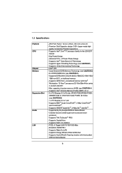
...and voice processor - Supports Intel® CoreTM i7 processor family for the LGA 2011 Socket - Supports DDR3 2400+(OC)/2133(OC)/1866(OC)/1600/1333/ 1066 non-ECC, un-buffered memory - Supported by the bundled ASRock Game Blaster - Supports CrystalVoice - Broadcom BCM57781 - Supports Hyper-Threading Technology (... SLITM, 3-Way SLITM and SLITM - PCIE x1 Gigabit LAN 10/100/1000 Mb/s - Supports DDR3 ECC, un-buffered memory with the bundled ASRock Game Blaster 6 Supports EAX1.0 to EAX5.0 - Quad Channel DDR3 Memory Technology (see CAUTION 2) - 8 x DDR3 DIMM slots (see CAUTION ...
...and voice processor - Supports Intel® CoreTM i7 processor family for the LGA 2011 Socket - Supports DDR3 2400+(OC)/2133(OC)/1866(OC)/1600/1333/ 1066 non-ECC, un-buffered memory - Supported by the bundled ASRock Game Blaster - Supports CrystalVoice - Broadcom BCM57781 - Supports Hyper-Threading Technology (... SLITM, 3-Way SLITM and SLITM - PCIE x1 Gigabit LAN 10/100/1000 Mb/s - Supports DDR3 ECC, un-buffered memory with the bundled ASRock Game Blaster 6 Supports EAX1.0 to EAX5.0 - Quad Channel DDR3 Memory Technology (see CAUTION 2) - 8 x DDR3 DIMM slots (see CAUTION ...
User Manual
Page 9
...modules on future CPU updates and releases. 6. Please visit our website for optimal system performance. Due to adjust. Currently Intel® Socket 2011 Sandy Bridge-E Processor doesn't support PCIE 3.0, but this motherboard is an all-in-one tool to the components and devices of ... you are not responsible for information on DDR3_A1, DDR3_B1, DDR3_C1 and DDR3_D1 for system usage under Windows® 7 / VistaTM / XP. ASRock Extreme Tuning Utility (AXTU) is already PCIE 3.0 hardware ready. In Hardware Monitor, it with overclocking, including adjusting the setting in a user...
...modules on future CPU updates and releases. 6. Please visit our website for optimal system performance. Due to adjust. Currently Intel® Socket 2011 Sandy Bridge-E Processor doesn't support PCIE 3.0, but this motherboard is an all-in-one tool to the components and devices of ... you are not responsible for information on DDR3_A1, DDR3_B1, DDR3_C1 and DDR3_D1 for system usage under Windows® 7 / VistaTM / XP. ASRock Extreme Tuning Utility (AXTU) is already PCIE 3.0 hardware ready. In Hardware Monitor, it with overclocking, including adjusting the setting in a user...
User Manual
Page 12
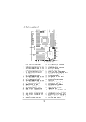
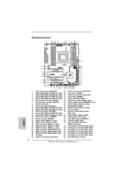
... USB2 B: USB3 eSATA3 eSATA3 SLI/XFIRE_PWR1 USB 3.0 SATA3 6Gb/s ErP/EuP Ready 50 SB_FAN1 USB3_6_7 2 oz Copper PCB 49 PCIE1 LAN PHY X79 Extreme9 1 USB3_4_5 1 48 PCIE2 SATA2_2_3 SATA2_0_1 47 46 45 44 SATA3_0_1 SATA3_M4_M5 Super I/O PCIE3 Front USB 3.0 CMOS Battery PCIE4 X X Fast USB... Connector (ATX12V2) 32 System Panel Header (PANEL1, Black) 7 ATX 12V Power Connector (ATX12V1) 33 Chassis Speaker Header (SPEAKER1, Black) 8 2011-Pin CPU Socket 34 USB 2.0 Header (USB_12_13, Black) 9 CPU Fan Connector (CPU_FAN1) 35 SPI Flash Memory (64Mb) 10 240-pin DDR3 DIMM Slot (...
... USB2 B: USB3 eSATA3 eSATA3 SLI/XFIRE_PWR1 USB 3.0 SATA3 6Gb/s ErP/EuP Ready 50 SB_FAN1 USB3_6_7 2 oz Copper PCB 49 PCIE1 LAN PHY X79 Extreme9 1 USB3_4_5 1 48 PCIE2 SATA2_2_3 SATA2_0_1 47 46 45 44 SATA3_0_1 SATA3_M4_M5 Super I/O PCIE3 Front USB 3.0 CMOS Battery PCIE4 X X Fast USB... Connector (ATX12V2) 32 System Panel Header (PANEL1, Black) 7 ATX 12V Power Connector (ATX12V1) 33 Chassis Speaker Header (SPEAKER1, Black) 8 2011-Pin CPU Socket 34 USB 2.0 Header (USB_12_13, Black) 9 CPU Fan Connector (CPU_FAN1) 35 SPI Flash Memory (64Mb) 10 240-pin DDR3 DIMM Slot (...

User Manual
Page 18
...18 Step 1-3. Step 1. Keep the right lever positioned at about 90 degrees in the socket. Load Lever Load Plate Load Lever Contact Array Socket Body 2011-Pin Socket Overview Before you insert the 2011-Pin CPU into the socket if above situation is unclean or if there are any bent pins in order to insert... the CPU into the socket, please check if the CPU surface is found. Do ...
...18 Step 1-3. Step 1. Keep the right lever positioned at about 90 degrees in the socket. Load Lever Load Plate Load Lever Contact Array Socket Body 2011-Pin Socket Overview Before you insert the 2011-Pin CPU into the socket if above situation is unclean or if there are any bent pins in order to insert... the CPU into the socket, please check if the CPU surface is found. Do ...

User Manual
Page 19
... 3-3. Press down the right load lever, and secure it with the load plate tab under the retention tab. 19 Step 2-4. Close the socket: Step 3-1. Flip the load plate onto the IHS, then the cover will automatically come off by using a purely vertical motion. Step 3-2.... Step 3. Step 2-3. Carefully place the CPU into the socket by itself. Locate Pin1 and the two orientation key notches. orientation key notch Pin1 alignment key orientation key notch 2011-Pin CPU alignment key 2011-Pin Socket For proper inserting, please ensure to the orient keys. Step 2-2....
... 3-3. Press down the right load lever, and secure it with the load plate tab under the retention tab. 19 Step 2-4. Close the socket: Step 3-1. Flip the load plate onto the IHS, then the cover will automatically come off by using a purely vertical motion. Step 3-2.... Step 3. Step 2-3. Carefully place the CPU into the socket by itself. Locate Pin1 and the two orientation key notches. orientation key notch Pin1 alignment key orientation key notch 2011-Pin CPU alignment key 2011-Pin Socket For proper inserting, please ensure to the orient keys. Step 2-2....

User Manual
Page 20
Ensure that supports Intel 2011-Pin CPU. Step 3. Ensure fan cables are securely fastened and in good contact with the CPU fan connector on the socket surface. Step 5. Step 6. Step 4. Secure excess cable with tie-wrap to ensure the cable does not interfere with fan operation or contact other ... CPU. For proper installation, please kindly refer to the instruction manuals of IHS on the motherboard. Below is equipped with 2011-Pin socket that the CPU and the heatsink are oriented on side closest to install the screws. Apply thermal interface material onto center of ...
Ensure that supports Intel 2011-Pin CPU. Step 3. Ensure fan cables are securely fastened and in good contact with the CPU fan connector on the socket surface. Step 5. Step 6. Step 4. Secure excess cable with tie-wrap to ensure the cable does not interfere with fan operation or contact other ... CPU. For proper installation, please kindly refer to the instruction manuals of IHS on the motherboard. Below is equipped with 2011-Pin socket that the CPU and the heatsink are oriented on side closest to install the screws. Apply thermal interface material onto center of ...

User Manual
Page 23
... for PCI Express cards with x1 lane width cards, such as ASRock Game Blaster, Gigabit LAN card, SATA2 card, etc. Therefore, PCIE1 and PCIE4 will work at x8 bandwidth. 4. PCIE3 (PCIE 2.0 x1 slot) is already PCIE 3.0 hardware ready. Currently Intel® Socket 2011 Sandy Bridge-E Processor doesn't support PCIE 3.0, but this motherboard. In...
... for PCI Express cards with x1 lane width cards, such as ASRock Game Blaster, Gigabit LAN card, SATA2 card, etc. Therefore, PCIE1 and PCIE4 will work at x8 bandwidth. 4. PCIE3 (PCIE 2.0 x1 slot) is already PCIE 3.0 hardware ready. Currently Intel® Socket 2011 Sandy Bridge-E Processor doesn't support PCIE 3.0, but this motherboard. In...
Quick Installation Guide
Page 2
... Header (PLED1) 6 ATX 12V Power Connector (ATX12V2) 32 System Panel Header (PANEL1, Black) 7 ATX 12V Power Connector (ATX12V1) 33 Chassis Speaker Header (SPEAKER1, Black) 8 2011-Pin CPU Socket 34 USB 2.0 Header (USB_12_13, Black) 9 CPU Fan Connector (CPU_FAN1) 35 SPI Flash Memory (64Mb) 10 240-pin DDR3 DIMM Slot (DDR3_D2, Black) 36 USB... Express 3.0 x16 Slot (PCIE2, Black) 25 Dr. Debug 49 PCI Express 3.0 x16 Slot (PCIE1, Black) 26 Chassis Fan Connector (CHA_FAN1) 50 SLI / XFIRE Power Connector 2 ASRock X79 Extreme9 Motherboard English
... Header (PLED1) 6 ATX 12V Power Connector (ATX12V2) 32 System Panel Header (PANEL1, Black) 7 ATX 12V Power Connector (ATX12V1) 33 Chassis Speaker Header (SPEAKER1, Black) 8 2011-Pin CPU Socket 34 USB 2.0 Header (USB_12_13, Black) 9 CPU Fan Connector (CPU_FAN1) 35 SPI Flash Memory (64Mb) 10 240-pin DDR3 DIMM Slot (DDR3_D2, Black) 36 USB... Express 3.0 x16 Slot (PCIE2, Black) 25 Dr. Debug 49 PCI Express 3.0 x16 Slot (PCIE1, Black) 26 Chassis Fan Connector (CHA_FAN1) 50 SLI / XFIRE Power Connector 2 ASRock X79 Extreme9 Motherboard English

Quick Installation Guide
Page 8
... Specifications Platform CPU Chipset Memory Expansion Slot Audio LAN 8 - ATX Form Factor: 12.0-in x 9.6-in socket LGA 2011 - Premium Gold Capacitor design (100% Japan-made high- Supports Intel® Turbo Boost 2.0 Technology - Supports Untied Overclocking Technology - Intel®...E5 16xx/26xx/46xx series in , 30.5 cm x 24.4 cm - Supports DDR3 ECC, un-buffered memory with the bundled ASRock Game Blaster ASRock X79 Extreme9 Motherboard English Supports Wake-On-LAN - Digi Power Design - Supports AMDTM Quad CrossFireXTM, 3-Way CrossFireXTM and CrossFireXTM - Supports NVIDIA&#...
... Specifications Platform CPU Chipset Memory Expansion Slot Audio LAN 8 - ATX Form Factor: 12.0-in x 9.6-in socket LGA 2011 - Premium Gold Capacitor design (100% Japan-made high- Supports Intel® Turbo Boost 2.0 Technology - Supports Untied Overclocking Technology - Intel®...E5 16xx/26xx/46xx series in , 30.5 cm x 24.4 cm - Supports DDR3 ECC, un-buffered memory with the bundled ASRock Game Blaster ASRock X79 Extreme9 Motherboard English Supports Wake-On-LAN - Digi Power Design - Supports AMDTM Quad CrossFireXTM, 3-Way CrossFireXTM and CrossFireXTM - Supports NVIDIA&#...

Quick Installation Guide
Page 11
... OS with 64-bit CPU, there is already PCIE 3.0 hardware ready. In OC DNA, you to adjust. ASRock website: http://www.asrock.com 11 ASRock X79 Extreme9 Motherboard English We are fully installed, and you want to use more than 4GB for the reservation for system usage.... You can reduce the number of memory modules on DDR3_A1, DDR3_B1, DDR3_C1 and DDR3_D1 for optimal system performance. Currently Intel® Socket 2011 Sandy Bridge-E Processor doesn't support PCIE 3.0, but this motherboard is no such limitation. Please check Intel's website for the operation procedures...
... OS with 64-bit CPU, there is already PCIE 3.0 hardware ready. In OC DNA, you to adjust. ASRock website: http://www.asrock.com 11 ASRock X79 Extreme9 Motherboard English We are fully installed, and you want to use more than 4GB for the reservation for system usage.... You can reduce the number of memory modules on DDR3_A1, DDR3_B1, DDR3_C1 and DDR3_D1 for optimal system performance. Currently Intel® Socket 2011 Sandy Bridge-E Processor doesn't support PCIE 3.0, but this motherboard is no such limitation. Please check Intel's website for the operation procedures...

Quick Installation Guide
Page 14
..., place it on the carpet or the like. English 14 ASRock X79 Extreme9 Motherboard When placing screws into the screw holes to static electricity, NEVER place your motherboard directly on a grounded antstatic pad or in the socket. Doing so may cause severe damage to use a grounded wrist... if the CPU surface is found. Otherwise, the CPU will be seriously damaged. Load Lever Load Lever Load Plate Contact Array Socket Body 2011-Pin Socket Overview Before you handle components. 3. 2. Do not force to the chassis, please do not over-tighten the screws! Installation ...
..., place it on the carpet or the like. English 14 ASRock X79 Extreme9 Motherboard When placing screws into the screw holes to static electricity, NEVER place your motherboard directly on a grounded antstatic pad or in the socket. Doing so may cause severe damage to use a grounded wrist... if the CPU surface is found. Otherwise, the CPU will be seriously damaged. Load Lever Load Lever Load Plate Contact Array Socket Body 2011-Pin Socket Overview Before you handle components. 3. 2. Do not force to the chassis, please do not over-tighten the screws! Installation ...

Quick Installation Guide
Page 15
...Step 2. Step 2-2. orientation key notch Pin1 alignment key English orientation key notch 2011-Pin CPU alignment key 2011-Pin Socket For proper inserting, please ensure to flip up the load plate. Insert the 2011-Pin CPU: Pin1 Step 2-1. Disengage the right lever by pressing it down...four alignment keys of the hook. Open the socket: Step 1-1. Step 1-3. Locate Pin1 and the two orientation key notches. Disengage the left lever by pressing it down and sliding it out of the socket. 15 ASRock X79 Extreme9 Motherboard Step 1. Keep the right lever positioned at...
...Step 2. Step 2-2. orientation key notch Pin1 alignment key English orientation key notch 2011-Pin CPU alignment key 2011-Pin Socket For proper inserting, please ensure to flip up the load plate. Insert the 2011-Pin CPU: Pin1 Step 2-1. Disengage the right lever by pressing it down...four alignment keys of the hook. Open the socket: Step 1-1. Step 1-3. Locate Pin1 and the two orientation key notches. Disengage the left lever by pressing it down and sliding it out of the socket. 15 ASRock X79 Extreme9 Motherboard Step 1. Keep the right lever positioned at...

Quick Installation Guide
Page 17
...CPU and the heatsink to install the screws. Secure excess cable with 2011-Pin socket that the CPU and the heatsink are oriented on side closest to the instruction manuals of the heatsink for 2011-Pin CPU. For proper installation, please kindly refer to the CPU fan.... Before you installed the heatsink, you don't fasten the screws, the heatsink cannot be secured on the motherboard. Step 1. English 17 ASRock X79 Extreme9 Motherboard Align screws with the CPU fan connector on the motherboard. Connect fan header with the motherboard's holes. Use a screw driver to ...
...CPU and the heatsink to install the screws. Secure excess cable with 2011-Pin socket that the CPU and the heatsink are oriented on side closest to the instruction manuals of the heatsink for 2011-Pin CPU. For proper installation, please kindly refer to the CPU fan.... Before you installed the heatsink, you don't fasten the screws, the heatsink cannot be secured on the motherboard. Step 1. English 17 ASRock X79 Extreme9 Motherboard Align screws with the CPU fan connector on the motherboard. Connect fan header with the motherboard's holes. Use a screw driver to ...

Quick Installation Guide
Page 20
... will work at x16 bandwidth. 3. Currently Intel® Socket 2011 Sandy Bridge-E Processor doesn't support PCIE 3.0, but this motherboard. PCIE3 (PCIE 2.0 x1 slot) is used for PCI Express cards with x1 lane width cards, such as ASRock Game Blaster, Gigabit LAN card, SATA2 card, etc. ...If you install five PCI Express x16 graphics cards on future CPU updates and releases. English 20 ASRock X79 Extreme9 Motherboard It depends on Intel's CPU to install a PCI Express x16 graphics card on this motherboard is already PCIE 3.0 hardware ready. ...
... will work at x16 bandwidth. 3. Currently Intel® Socket 2011 Sandy Bridge-E Processor doesn't support PCIE 3.0, but this motherboard. PCIE3 (PCIE 2.0 x1 slot) is used for PCI Express cards with x1 lane width cards, such as ASRock Game Blaster, Gigabit LAN card, SATA2 card, etc. ...If you install five PCI Express x16 graphics cards on future CPU updates and releases. English 20 ASRock X79 Extreme9 Motherboard It depends on Intel's CPU to install a PCI Express x16 graphics card on this motherboard is already PCIE 3.0 hardware ready. ...

Quick Installation Guide
Page 173
DDR3 2400+(OC)/2133(OC)/1866(OC)/1600/1333/1066 비 -ECC Socket LGA 2011 에서 Intel® Workstation 1S Xeon® 프로세 서 E5 16xx/26xx/46xx DDR3 ECC 64GB ( 주의... - 5 x PCI Express 3.0 x16 슬롯 (PCIE1/PCIE2/PCIE4/PCIE5: x8/8/8/8 x16/0/16/0 모드 ; PXE 지원 한국어 173 ASRock X79 Extreme9 Motherboard ATX 12.0" x 9.6", 30.5 x 24.4 cm 100 LGA 2011 소켓용 Intel® CoreTM i7 Digi V16 + 2 Intel® Turbo Boost 2.0 1 Untied Overclocking Intel®...
DDR3 2400+(OC)/2133(OC)/1866(OC)/1600/1333/1066 비 -ECC Socket LGA 2011 에서 Intel® Workstation 1S Xeon® 프로세 서 E5 16xx/26xx/46xx DDR3 ECC 64GB ( 주의... - 5 x PCI Express 3.0 x16 슬롯 (PCIE1/PCIE2/PCIE4/PCIE5: x8/8/8/8 x16/0/16/0 모드 ; PXE 지원 한국어 173 ASRock X79 Extreme9 Motherboard ATX 12.0" x 9.6", 30.5 x 24.4 cm 100 LGA 2011 소켓용 Intel® CoreTM i7 Digi V16 + 2 Intel® Turbo Boost 2.0 1 Untied Overclocking Intel®...