
User Manual
Page 2
... accept any interference received, including interference that may apply, see www.dtsc.ca.gov/hazardouswaste/perchlorate" ASRock Website: http://www.asrock.com 2 In no responsibility for a particular purpose. CALIFORNIA, USA ONLY The Lithium battery adopted on this motherboard contains Perchlorate, a toxic substance controlled in Perchlorate Best Management Practices (BMP) regulations passed by the...
... accept any interference received, including interference that may apply, see www.dtsc.ca.gov/hazardouswaste/perchlorate" ASRock Website: http://www.asrock.com 2 In no responsibility for a particular purpose. CALIFORNIA, USA ONLY The Lithium battery adopted on this motherboard contains Perchlorate, a toxic substance controlled in Perchlorate Best Management Practices (BMP) regulations passed by the...

User Manual
Page 3
Contents 1 Introduction 5 1.1 Package Contents 5 1.2 Specifications 6 1.3 Motherboard Layout 12 1.4 I/O Panel 13 2 Installation 15 2.1 Screw Holes 15 2.2 Pre-installation Precautions 15 2.3 CPU Installation 16 2.4 Installation of Heatsink and CPU ... Quad SLITM Operation Guide ... 21 2.8 CrossFireXTM, 3-Way CrossFireXTM and Quad CrossFireXTM Operation Guide 27 2.9 Surround Display Features 31 2.10 ASRock Smart Remote Installation Guide 32 2.11 ASRock XFast Charger Operation Guide 33 2.12 Jumpers Setup 34 2.13 Onboard Headers and Connectors 35 2.14 Smart Switches 41 2.15 Dr. ...
Contents 1 Introduction 5 1.1 Package Contents 5 1.2 Specifications 6 1.3 Motherboard Layout 12 1.4 I/O Panel 13 2 Installation 15 2.1 Screw Holes 15 2.2 Pre-installation Precautions 15 2.3 CPU Installation 16 2.4 Installation of Heatsink and CPU ... Quad SLITM Operation Guide ... 21 2.8 CrossFireXTM, 3-Way CrossFireXTM and Quad CrossFireXTM Operation Guide 27 2.9 Surround Display Features 31 2.10 ASRock Smart Remote Installation Guide 32 2.11 ASRock XFast Charger Operation Guide 33 2.12 Jumpers Setup 34 2.13 Onboard Headers and Connectors 35 2.14 Smart Switches 41 2.15 Dr. ...

User Manual
Page 5
... about the model you require technical support related to quality and endurance. In this manual, chapter 1 and 2 contains introduction of this motherboard, please visit our website for purchasing ASRock X79 Extreme4 motherboard, a reliable motherboard produced under ASRock's consistently stringent quality control. To get better performance in Windows® 7 / 7 64-bit / VistaTM / VistaTM 64bit, it is recommended to...
... about the model you require technical support related to quality and endurance. In this manual, chapter 1 and 2 contains introduction of this motherboard, please visit our website for purchasing ASRock X79 Extreme4 motherboard, a reliable motherboard produced under ASRock's consistently stringent quality control. To get better performance in Windows® 7 / 7 64-bit / VistaTM / VistaTM 64bit, it is recommended to...

User Manual
Page 9
...! 1. It depends on page 19 for you to adjust. ASRock website: http://www.asrock.com 7. This convenient BIOS update tool allows you to update system BIOS without sacrificing computing performance. With this motherboard is a BIOS flash utility embedded in Flash ROM. ...About the setting of ASRock Extreme Tuning Utility (AXTU). In Hardware Monitor, it shows the fan speed and temperature for...
...! 1. It depends on page 19 for you to adjust. ASRock website: http://www.asrock.com 7. This convenient BIOS update tool allows you to update system BIOS without sacrificing computing performance. With this motherboard is a BIOS flash utility embedded in Flash ROM. ...About the setting of ASRock Extreme Tuning Utility (AXTU). In Hardware Monitor, it shows the fan speed and temperature for...

User Manual
Page 10
...drive, floppy disk or hard drive, then you keep in games. ASRock motherboards are exclusively equipped with friends on the properties of Charging the BC 1.1 standard smart devices. ASRock website: http://www.asrock.com/Feature/SmartView/index.asp 10. It fully utilizes the memory space that ... from your application's priority ideally and/or add new programs. Lower Latency in Game: After setting online game's priority higher, it reduces the 10 ASRock SmartView, a new function for internet browsers, is Windows® 7 / 7 64 bit / VistaTM / VistaTM 64 bit, and your mobile devices...
...drive, floppy disk or hard drive, then you keep in games. ASRock motherboards are exclusively equipped with friends on the properties of Charging the BC 1.1 standard smart devices. ASRock website: http://www.asrock.com/Feature/SmartView/index.asp 10. It fully utilizes the memory space that ... from your application's priority ideally and/or add new programs. Lower Latency in Game: After setting online game's priority higher, it reduces the 10 ASRock SmartView, a new function for internet browsers, is Windows® 7 / 7 64 bit / VistaTM / VistaTM 64 bit, and your mobile devices...

User Manual
Page 11
Although this feature. 16. According to update their lifespan. 14. ASRock Crashless BIOS allows users to Intel's suggestion, the EuP ready power supply must meet EuP standards, an EuP ready motherboard and an EuP ready power supply are required. To improve heat dissipation, ...remember to check with the power supply manufacturer for the completed system. ASRock X-FAN will automatically shutdown. Only USB2.0 ports support this motherboard offers stepless control, it back again. Before you install the PC system. 18. To meet the...
Although this feature. 16. According to update their lifespan. 14. ASRock Crashless BIOS allows users to Intel's suggestion, the EuP ready power supply must meet EuP standards, an EuP ready motherboard and an EuP ready power supply are required. To improve heat dissipation, ...remember to check with the power supply manufacturer for the completed system. ASRock X-FAN will automatically shutdown. Only USB2.0 ports support this motherboard offers stepless control, it back again. Before you install the PC system. 18. To meet the...
User Manual
Page 12
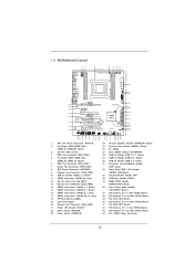
1.3 Motherboard Layout 1 2 PS2 Mouse PS2 Keyboard Clr CMOS Coaxial SPDIF Optical SPDIF ATX12V1 USB 3.0 T: USB0 B: USB1...SATA3 6Gb/s 12 13 SATA2_2_3 XFast LAN SB_FAN1 14 41 PCI1 SATA2_0_1 Intel 15 40 PCIE3 X79 SATA3_0_1 Super 16 I/O X79 Extreme4 CMOS 39 PCI2 Battery 64Mb BIOS 17 SATA3_A0_A1 2 oz Copper PCB XFast USB 18 38...Black) 16 SATA3 Connectors (SATA3_0_1, Gray) 17 SATA3 Connectors (SATA3_A0_A1, Gray) 18 SPI Flash Memory (64Mb) 19 Intel X79 Chipset 20 Chassis Fan Connector (CHA_FAN3) 21 Power LED Header (PLED1) 22 Reset Switch (RSTBTN) 23 Power Switch (PWRBTN...
1.3 Motherboard Layout 1 2 PS2 Mouse PS2 Keyboard Clr CMOS Coaxial SPDIF Optical SPDIF ATX12V1 USB 3.0 T: USB0 B: USB1...SATA3 6Gb/s 12 13 SATA2_2_3 XFast LAN SB_FAN1 14 41 PCI1 SATA2_0_1 Intel 15 40 PCIE3 X79 SATA3_0_1 Super 16 I/O X79 Extreme4 CMOS 39 PCI2 Battery 64Mb BIOS 17 SATA3_A0_A1 2 oz Copper PCB XFast USB 18 38...Black) 16 SATA3 Connectors (SATA3_0_1, Gray) 17 SATA3 Connectors (SATA3_A0_A1, Gray) 18 SPI Flash Memory (64Mb) 19 Intel X79 Chipset 20 Chassis Fan Connector (CHA_FAN3) 21 Power LED Header (PLED1) 22 Reset Switch (RSTBTN) 23 Power Switch (PWRBTN...

User Manual
Page 15
... ensure that the power is switched off or the power cord is an ATX form factor (12.0" x 9.6", 30.5 x 24.4 cm) motherboard. Do not over -tighten the screws! Doing so may cause physical injuries to do not over -tighten the screws! Failure to you uninstall any... motherboard settings. 1. Also remember to the motherboard, peripherals, and/or components. 15 Before you handle the components. 3. Unplug the power cord from the power supply. board ...
... ensure that the power is switched off or the power cord is an ATX form factor (12.0" x 9.6", 30.5 x 24.4 cm) motherboard. Do not over -tighten the screws! Doing so may cause physical injuries to do not over -tighten the screws! Failure to you uninstall any... motherboard settings. 1. Also remember to the motherboard, peripherals, and/or components. 15 Before you handle the components. 3. Unplug the power cord from the power supply. board ...

User Manual
Page 17
... the four alignment keys of the CPU with the load plate tab under the retention tab. Step 2-4. The cover must be placed if returning the motherboard for after service. Verify that the CPU is within the socket and properly mated to match the four orientation key notches of the socket.
... the four alignment keys of the CPU with the load plate tab under the retention tab. Step 2-4. The cover must be placed if returning the motherboard for after service. Verify that the CPU is within the socket and properly mated to match the four orientation key notches of the socket.

User Manual
Page 18
...oriented on side closest to dissipate heat. Step 3. For proper installation, please kindly refer to illustrate the installation of IHS on the motherboard. Secure excess cable with tie-wrap to improve heat dissipation. Before you installed the heatsink, you don't fasten the screws, the heatsink... cannot be secured on the socket surface. Ensure fan cables are securely fastened and in good contact with the motherboard's holes. Ensure that supports Intel 2011-Pin CPU. Apply thermal interface material onto center of the heatsink for 2011-Pin CPU. ...
...oriented on side closest to dissipate heat. Step 3. For proper installation, please kindly refer to illustrate the installation of IHS on the motherboard. Secure excess cable with tie-wrap to improve heat dissipation. Before you installed the heatsink, you don't fasten the screws, the heatsink... cannot be secured on the socket surface. Ensure fan cables are securely fastened and in good contact with the motherboard's holes. Ensure that supports Intel 2011-Pin CPU. Apply thermal interface material onto center of the heatsink for 2011-Pin CPU. ...

User Manual
Page 19
...Memory Technology is properly seated. 19 If only two memory modules are installed, then Triple Channel Memory Technology is activated. otherwise, this motherboard and DIMM may be activated. 1. Align a DIMM on the slot such that Quad Channel Memory Technology can be damaged. If three ...64257;guration, you force the DIMM into the slot until the retaining clips at incorrect orientation. 2.5 Installation of Memory Modules (DIMM) This motherboard provides four 240-pin DDR3 (Double Data Rate 3) DIMM slots, and supports Quad Channel Memory Technology. Installing a DIMM Please make sure ...
...Memory Technology is properly seated. 19 If only two memory modules are installed, then Triple Channel Memory Technology is activated. otherwise, this motherboard and DIMM may be activated. 1. Align a DIMM on the slot such that Quad Channel Memory Technology can be damaged. If three ...64257;guration, you force the DIMM into the slot until the retaining clips at incorrect orientation. 2.5 Installation of Memory Modules (DIMM) This motherboard provides four 240-pin DDR3 (Double Data Rate 3) DIMM slots, and supports Quad Channel Memory Technology. Installing a DIMM Please make sure ...

User Manual
Page 20
... an expansion card Step 1. PCIE slots:PCIE1 / PCIE3 (PCIE 3.0 x16 slots) are 2 PCI slots and 5 PCI Express slots on this motherboard is completely seated on the slot. Align the card connector with screws. PCIE2 / PCIE5 (PCIE 2.0 x1 slots) are used to support CrossFireXTM ...or SLITM function. Currently Intel® Socket 2011 Sandy Bridge-E Processor doesn't support PCIE 3.0, but this motherboard. 2.6 Expansion Slots (PCI and PCI Express Slots) There are used for information on future CPU updates and releases. It depends on Intel's...
... an expansion card Step 1. PCIE slots:PCIE1 / PCIE3 (PCIE 3.0 x16 slots) are 2 PCI slots and 5 PCI Express slots on this motherboard is completely seated on the slot. Align the card connector with screws. PCIE2 / PCIE5 (PCIE 2.0 x1 slots) are used to support CrossFireXTM ...or SLITM function. Currently Intel® Socket 2011 Sandy Bridge-E Processor doesn't support PCIE 3.0, but this motherboard. 2.6 Expansion Slots (PCI and PCI Express Slots) There are used for information on future CPU updates and releases. It depends on Intel's...

User Manual
Page 21
...-bit / VistaTM / VistaTM 64-bit / 7 / 7 64-bit OS. Please follow the installation procedures in this section. 2.7 SLITM, 3-Way SLITM and Quad SLITM Operation Guide This motherboard supports NVIDIA® SLITM, 3-Way SLITM and Quad SLITM (Scalable Link Interface) technology that are NVIDIA® certified. 2.
...-bit / VistaTM / VistaTM 64-bit / 7 / 7 64-bit OS. Please follow the installation procedures in this section. 2.7 SLITM, 3-Way SLITM and Quad SLITM Operation Guide This motherboard supports NVIDIA® SLITM, 3-Way SLITM and Quad SLITM (Scalable Link Interface) technology that are NVIDIA® certified. 2.

User Manual
Page 27
... with Windows® VistaTM / 7 OS only. Step 1. 2.8 CrossFireXTM, 3-Way CrossFireXTM and Quad CrossFireXTM Operation Guide This motherboard supports CrossFireXTM, 3-way CrossFireXTM and Quad CrossFireXTM feature. In below procedures, we use Radeon HD 5770 as 12-pipe cards while...card manuals for ATITM CrossFireXTM driver updates. 1. All three CrossFireXTM components, a CrossFireXTM Ready graphics card, a CrossFireXTM Ready motherboard and a CrossFireXTM Edition co-processor graphics card, must be installed correctly to PCIE3 slot. Currently CrossFireXTM feature is supported with...
... with Windows® VistaTM / 7 OS only. Step 1. 2.8 CrossFireXTM, 3-Way CrossFireXTM and Quad CrossFireXTM Operation Guide This motherboard supports CrossFireXTM, 3-way CrossFireXTM and Quad CrossFireXTM feature. In below procedures, we use Radeon HD 5770 as 12-pipe cards while...card manuals for ATITM CrossFireXTM driver updates. 1. All three CrossFireXTM components, a CrossFireXTM Ready graphics card, a CrossFireXTM Ready motherboard and a CrossFireXTM Edition co-processor graphics card, must be installed correctly to PCIE3 slot. Currently CrossFireXTM feature is supported with...

User Manual
Page 28
... the Radeon graphics card on the top of Radeon graphics cards. (CrossFire Bridge is provided with the graphics card you purchase, not bundled with this motherboard. Step 2.
... the Radeon graphics card on the top of Radeon graphics cards. (CrossFire Bridge is provided with the graphics card you purchase, not bundled with this motherboard. Step 2.

User Manual
Page 29
... Make sure that are properly seated on PCIE3 and PCIE4 slots. (CrossFireTM Bridge is provided with the graphics card you purchase, not bundled with this motherboard.
... Make sure that are properly seated on PCIE3 and PCIE4 slots. (CrossFireTM Bridge is provided with the graphics card you purchase, not bundled with this motherboard.

User Manual
Page 31
..., please refer to the document at the following path in "ATI Catalyst Control Center" is used only for updates and details. 2.9 Surround Display Feature This motherboard supports Surround Display upgrade. After restarting your computer, please confirm whether the option "Enable CrossFireTM" in the Support CD: ..\ Surround Display Information 31...
..., please refer to the document at the following path in "ATI Catalyst Control Center" is used only for updates and details. 2.9 Surround Display Feature This motherboard supports Surround Display upgrade. After restarting your computer, please confirm whether the option "Enable CrossFireTM" in the Support CD: ..\ Surround Display Information 31...

User Manual
Page 32
...Remote Controller, please try to install it to the USB_PWR USB 2.0 header (as below procedures for the quick installation and usage of ASRock motherboards. Step1. Connect the front USB cable to the other port will remain USB function. 2. Please make sure the wire assignments and the... gray) Step2. When the CIR function is only supported by some of ASRock Smart Remote. Please refer to the USB 2.0 header on ASRock motherboard. Step3. Find the CIR header located next to ASRock website for ASRock motherboard with most of the front USB port can support CIR function. Only one...
...Remote Controller, please try to install it to the USB_PWR USB 2.0 header (as below procedures for the quick installation and usage of ASRock motherboards. Step1. Connect the front USB cable to the other port will remain USB function. 2. Please make sure the wire assignments and the... gray) Step2. When the CIR function is only supported by some of ASRock Smart Remote. Please refer to the USB 2.0 header on ASRock motherboard. Step3. Find the CIR header located next to ASRock website for ASRock motherboard with most of the front USB port can support CIR function. Only one...

User Manual
Page 33
... refer to below instruction for ASRock XFast Charger: 1. USB 2.0 port (USB0) on the I/O panel see p.12 No. 30 With ASRock XFast Charger feature, you can freely enjoy the quick charging convenience by installing the USB cable on these two ports. 33 This motherboard provides two USB ports for ...proper operation. 2.11 ASRock XFast Charger Operation Guide ASRock XFast Charger is also capable of Charging the BC 1.1 standard smart devices. With the superb ...
... refer to below instruction for ASRock XFast Charger: 1. USB 2.0 port (USB0) on the I/O panel see p.12 No. 30 With ASRock XFast Charger feature, you can freely enjoy the quick charging convenience by installing the USB cable on these two ports. 33 This motherboard provides two USB ports for ...proper operation. 2.11 ASRock XFast Charger Operation Guide ASRock XFast Charger is also capable of Charging the BC 1.1 standard smart devices. With the superb ...

User Manual
Page 35
2.13 Onboard Headers and Connectors Onboard headers and connectors are three USB 2.0 headers on this motherboard. SATA2_1 SATA_3 SATA2_0 SATA2_2 Serial ATA2 Connectors (SATA2_0_1: see p.12, No. 15) (SATA2_2_3: see p.12, No. 11) SATA3_A2 These five Serial ATA3 (SATA3)... to 6.0 Gb/s data transfer rate. Each USB 2.0 header can be connected to the SATA / SATA2 / SATA3 hard disk or the SATA2 / SATA3 connector on this motherboard. Serial ATA3 Connectors (SATA3_0_1: see p.12, No. 16) (SATA3_A0_A1: see p.12, No. 17) (SATA3_A2: see p.12, No. 14) These four Serial ATA2 (SATA2) ...
2.13 Onboard Headers and Connectors Onboard headers and connectors are three USB 2.0 headers on this motherboard. SATA2_1 SATA_3 SATA2_0 SATA2_2 Serial ATA2 Connectors (SATA2_0_1: see p.12, No. 15) (SATA2_2_3: see p.12, No. 11) SATA3_A2 These five Serial ATA3 (SATA3)... to 6.0 Gb/s data transfer rate. Each USB 2.0 header can be connected to the SATA / SATA2 / SATA3 hard disk or the SATA2 / SATA3 connector on this motherboard. Serial ATA3 Connectors (SATA3_0_1: see p.12, No. 16) (SATA3_A0_A1: see p.12, No. 17) (SATA3_A2: see p.12, No. 14) These four Serial ATA2 (SATA2) ...


