
User Manual
Page 6
Supports Intel® CoreTM i7 processor family for the LGA 2011 Socket - Advanced 5 + 1 Power Phase Design - Supports DDR3 2400+(OC)/1600/1333/1066/800 non-ECC, un-buffered memory - Supports AMDTM Quad CrossFireXTM, 3-...ficient Ethernet 802.3az - quality Conductive Polymer Capacitors) - Supports Intel® Turbo Boost 2.0 Technology - Max. Supports THX TruStudioTM - Supports Wake-On-LAN - Intel® X79 - Quad Channel DDR3 Memory Technology (see CAUTION 4) - 1 x PCI Express 2.0 x 1 slot - 2 x PCI slots - Supports NVIDIA® Quad SLITM, 3-Way SLITM and SLITM -...
Supports Intel® CoreTM i7 processor family for the LGA 2011 Socket - Advanced 5 + 1 Power Phase Design - Supports DDR3 2400+(OC)/1600/1333/1066/800 non-ECC, un-buffered memory - Supports AMDTM Quad CrossFireXTM, 3-...ficient Ethernet 802.3az - quality Conductive Polymer Capacitors) - Supports Intel® Turbo Boost 2.0 Technology - Max. Supports THX TruStudioTM - Supports Wake-On-LAN - Intel® X79 - Quad Channel DDR3 Memory Technology (see CAUTION 4) - 1 x PCI Express 2.0 x 1 slot - 2 x PCI slots - Supports NVIDIA® Quad SLITM, 3-Way SLITM and SLITM -...

User Manual
Page 9
... allowed to adjust. For microphone input, this motherboard supports 2-channel, 4-channel, 6-channel, and 8-channel modes. ASRock Extreme Tuning Utility (AXTU) is already PCIE 3.0 hardware ready. In Fan Control, it shows the fan speed ...ASRock Extreme Tuning Utility (AXTU). For audio output, this motherboard supports both stereo and mono modes. With this motherboard is an all-in a user-friendly interface, which includes Hardware Monitor, Fan Control, Overclocking, OC DNA and IES. WARNING Please realize that Windows® cannot use. 4. CAUTION! 1. Currently Intel® Socket 2011...
... allowed to adjust. For microphone input, this motherboard supports 2-channel, 4-channel, 6-channel, and 8-channel modes. ASRock Extreme Tuning Utility (AXTU) is already PCIE 3.0 hardware ready. In Fan Control, it shows the fan speed ...ASRock Extreme Tuning Utility (AXTU). For audio output, this motherboard supports both stereo and mono modes. With this motherboard is an all-in a user-friendly interface, which includes Hardware Monitor, Fan Control, Overclocking, OC DNA and IES. WARNING Please realize that Windows® cannot use. 4. CAUTION! 1. Currently Intel® Socket 2011...
User Manual
Page 12
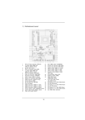
...Clear CMOS Jumper (CLRCMOS1) 2 2 x 240-pin DDR3 DIMM Slots 22 Chassis Fan Connector (CHA_FAN3) (DDR3_A1, DDR3_B1, Black) 23 Chassis Fan Connector (CHA_FAN1) 3 2011-Pin CPU Socket 24 USB 2.0 Header (USB_10_11, Black) 4 CPU Fan Connector (CPU_FAN2) 25 USB 2.0 Header (USB_8_9, Black) 5 2 x 240-pin DDR3 DIMM Slots 26 ...12 SPI Flash Memory (64Mb) (HD_AUDIO1, Black) 13 SB Fan Connector (SB_FAN1) 32 PCI Express 3.0 x16 Slot (PCIE4, Black) 14 Intel X79 Chipset 33 PCI Slot (PCI2, Black) 15 SATA3 Connectors (SATA3_0_1, Gray) 34 PCI Express 3.0 x16 Slot (PCIE3, Black) 16 SATA2 Connectors ...
...Clear CMOS Jumper (CLRCMOS1) 2 2 x 240-pin DDR3 DIMM Slots 22 Chassis Fan Connector (CHA_FAN3) (DDR3_A1, DDR3_B1, Black) 23 Chassis Fan Connector (CHA_FAN1) 3 2011-Pin CPU Socket 24 USB 2.0 Header (USB_10_11, Black) 4 CPU Fan Connector (CPU_FAN2) 25 USB 2.0 Header (USB_8_9, Black) 5 2 x 240-pin DDR3 DIMM Slots 26 ...12 SPI Flash Memory (64Mb) (HD_AUDIO1, Black) 13 SB Fan Connector (SB_FAN1) 32 PCI Express 3.0 x16 Slot (PCIE4, Black) 14 Intel X79 Chipset 33 PCI Slot (PCI2, Black) 15 SATA3 Connectors (SATA3_0_1, Gray) 34 PCI Express 3.0 x16 Slot (PCIE3, Black) 16 SATA2 Connectors ...

User Manual
Page 16
Step 1-3. Step 2. Insert the 2011-Pin CPU: Pin1 Step 2-1. Open the socket: Step 1-1. 2.3 CPU Installation For the installation of Intel 2011-Pin CPU, please follow the steps below. 2011-Pin Socket Overview Before you insert the 2011-Pin CPU into the socket if above situation is unclean or if there are any bent... pins in order to insert the CPU into the socket, please check if the...
Step 1-3. Step 2. Insert the 2011-Pin CPU: Pin1 Step 2-1. Open the socket: Step 1-1. 2.3 CPU Installation For the installation of Intel 2011-Pin CPU, please follow the steps below. 2011-Pin Socket Overview Before you insert the 2011-Pin CPU into the socket if above situation is unclean or if there are any bent... pins in order to insert the CPU into the socket, please check if the...

User Manual
Page 17
... itself. Press down the right load lever, and secure it with the four alignment keys of the socket. Step 3. Close the socket: Step 3-1. Press down the left load lever, and secure it with the load plate tab under the retention tab. 17 Step 3-3. Locate Pin1 and the ...two orientation key notches. Step 2-3. Step 2-4. The cover must be placed if returning the motherboard for after service. Verify that the CPU is within the socket and properly mated to match the four orientation key notches of the CPU with the load plate tab under the retention tab. orientation key notch...
... itself. Press down the right load lever, and secure it with the four alignment keys of the socket. Step 3. Close the socket: Step 3-1. Press down the left load lever, and secure it with the load plate tab under the retention tab. 17 Step 3-3. Locate Pin1 and the ...two orientation key notches. Step 2-3. Step 2-4. The cover must be placed if returning the motherboard for after service. Verify that the CPU is within the socket and properly mated to match the four orientation key notches of the CPU with the load plate tab under the retention tab. orientation key notch...

User Manual
Page 18
...heat. Please adopt the type of CPU Fan and Heatsink This motherboard is an example to illustrate the installation of IHS on the socket surface. Ensure that supports Intel 2011-Pin CPU. Step 2. Use a screw driver to the instruction manuals of your CPU fan and heatsink. Step 5. Below is... fan operation or contact other . Apply thermal interface material onto center of the heatsink for 2011-Pin CPU. Then connect the CPU fan to ensure the cable does not interfere with 2011-Pin socket that the CPU and the heatsink are oriented on the motherboard (CPU_ FAN1, see page 12...
...heat. Please adopt the type of CPU Fan and Heatsink This motherboard is an example to illustrate the installation of IHS on the socket surface. Ensure that supports Intel 2011-Pin CPU. Step 2. Use a screw driver to the instruction manuals of your CPU fan and heatsink. Step 5. Below is... fan operation or contact other . Apply thermal interface material onto center of the heatsink for 2011-Pin CPU. Then connect the CPU fan to ensure the cable does not interfere with 2011-Pin socket that the CPU and the heatsink are oriented on the motherboard (CPU_ FAN1, see page 12...

User Manual
Page 20
...card Step 1. Fasten the card to the chassis with the slot and press firmly until the card is used to install an ASRock Game Blaster card. 1. In CrossFireXTM mode or SLITM mode, please install PCI Express x16 graphics cards on PCIE1, PCIE3 and PCIE4 slots... Intel's CPU to motherboard chassis fan connector (CHA_FAN1, CHA_FAN2 or CHA_FAN3) when using multiple graphics cards for later use . Currently Intel® Socket 2011 Sandy Bridge-E Processor doesn't support PCIE 3.0, but this motherboard. Therefore, both these two slots will work at x8 bandwidth. 4. It depends on...
...card Step 1. Fasten the card to the chassis with the slot and press firmly until the card is used to install an ASRock Game Blaster card. 1. In CrossFireXTM mode or SLITM mode, please install PCI Express x16 graphics cards on PCIE1, PCIE3 and PCIE4 slots... Intel's CPU to motherboard chassis fan connector (CHA_FAN1, CHA_FAN2 or CHA_FAN3) when using multiple graphics cards for later use . Currently Intel® Socket 2011 Sandy Bridge-E Processor doesn't support PCIE 3.0, but this motherboard. Therefore, both these two slots will work at x8 bandwidth. 4. It depends on...
Quick Installation Guide
Page 2
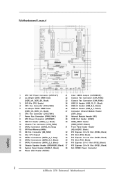
... 2 x 240-pin DDR3 DIMM Slots 22 Chassis Fan Connector (CHA_FAN3) (DDR3_A1, DDR3_B1, Black) 23 Chassis Fan Connector (CHA_FAN1) 3 2011-Pin CPU Socket 24 USB 2.0 Header (USB_10_11, Black) 4 CPU Fan Connector (CPU_FAN2) 25 USB 2.0 Header (USB_8_9, Black) 5 2 x 240...) (HD_AUDIO1, Black) 13 SB Fan Connector (SB_FAN1) 32 PCI Express 3.0 x16 Slot (PCIE4, Black) 14 Intel X79 Chipset 33 PCI Slot (PCI2, Black) 15 SATA3 Connectors (SATA3_0_1, Gray) 34 PCI Express 3.0 x16 Slot (PCIE3...) 38 SLI / XFIRE Power Connector 20 Power LED Header (PLED1) 2 ASRock X79 Extreme3 Motherboard English
... 2 x 240-pin DDR3 DIMM Slots 22 Chassis Fan Connector (CHA_FAN3) (DDR3_A1, DDR3_B1, Black) 23 Chassis Fan Connector (CHA_FAN1) 3 2011-Pin CPU Socket 24 USB 2.0 Header (USB_10_11, Black) 4 CPU Fan Connector (CPU_FAN2) 25 USB 2.0 Header (USB_8_9, Black) 5 2 x 240...) (HD_AUDIO1, Black) 13 SB Fan Connector (SB_FAN1) 32 PCI Express 3.0 x16 Slot (PCIE4, Black) 14 Intel X79 Chipset 33 PCI Slot (PCI2, Black) 15 SATA3 Connectors (SATA3_0_1, Gray) 34 PCI Express 3.0 x16 Slot (PCIE3...) 38 SLI / XFIRE Power Connector 20 Power LED Header (PLED1) 2 ASRock X79 Extreme3 Motherboard English

Quick Installation Guide
Page 6
...Premium Blu-ray audio support - PCIE4: x8 mode) (see CAUTION 3) - ATX Form Factor: 12.0-in x 8.8-in socket LGA 2011 - Supports Hyper-Threading Technology (see CAUTION 2) - 4 x DDR3 DIMM slots - Quad Channel DDR3 Memory Technology (see...2011 Socket - Supports DDR3 ECC, un-buffered memory with Content Protection (Realtek ALC898 Audio Codec) - Premium Gold Capacitor design (100% Japan-made high- Digi Power Design - 1.2 Specifications Platform CPU Chipset Memory Expansion Slot Audio LAN Rear Panel I /O Panel - 1 x PS/2 Mouse Port - 1 x PS/2 Keyboard Port ASRock X79 Extreme3...
...Premium Blu-ray audio support - PCIE4: x8 mode) (see CAUTION 3) - ATX Form Factor: 12.0-in x 8.8-in socket LGA 2011 - Supports Hyper-Threading Technology (see CAUTION 2) - 4 x DDR3 DIMM slots - Quad Channel DDR3 Memory Technology (see...2011 Socket - Supports DDR3 ECC, un-buffered memory with Content Protection (Realtek ALC898 Audio Codec) - Premium Gold Capacitor design (100% Japan-made high- Digi Power Design - 1.2 Specifications Platform CPU Chipset Memory Expansion Slot Audio LAN Rear Panel I /O Panel - 1 x PS/2 Mouse Port - 1 x PS/2 Keyboard Port ASRock X79 Extreme3...

Quick Installation Guide
Page 9
Currently Intel® Socket 2011 Sandy Bridge-E Processor doesn't support PCIE 3.0, but this motherboard is no such limitation. It depends on page 16 for proper installation. 3. In Fan Control, ...system functions in a user-friendly interface, which includes Hardware Monitor, Fan Control, Overclocking, OC DNA and IES. This motherboard supports Quad Channel Memory Technology. With 9 ASRock X79 Extreme3 Motherboard English Before you are not responsible for system usage under Windows® 7 / VistaTM / XP. For Windows® OS with overclocking, including adjusting the ...
Currently Intel® Socket 2011 Sandy Bridge-E Processor doesn't support PCIE 3.0, but this motherboard is no such limitation. It depends on page 16 for proper installation. 3. In Fan Control, ...system functions in a user-friendly interface, which includes Hardware Monitor, Fan Control, Overclocking, OC DNA and IES. This motherboard supports Quad Channel Memory Technology. With 9 ASRock X79 Extreme3 Motherboard English Before you are not responsible for system usage under Windows® 7 / VistaTM / XP. For Windows® OS with overclocking, including adjusting the ...

Quick Installation Guide
Page 12
...2011-Pin CPU into the socket, please check if the CPU surface is found. To avoid damaging the motherboard components due to use a grounded wrist strap or touch a safety grounded object before you uninstall any motherboard settings. 1. Whenever you handle components. 3. Otherwise, the CPU will be seriously damaged. 12 ASRock X79 Extreme3... Motherboard English When placing screws into the socket if above situation is unclean or if there are any component. Do not force to ...
...2011-Pin CPU into the socket, please check if the CPU surface is found. To avoid damaging the motherboard components due to use a grounded wrist strap or touch a safety grounded object before you uninstall any motherboard settings. 1. Whenever you handle components. 3. Otherwise, the CPU will be seriously damaged. 12 ASRock X79 Extreme3... Motherboard English When placing screws into the socket if above situation is unclean or if there are any component. Do not force to ...

Quick Installation Guide
Page 13
... notches. Hold the CPU by pressing it down and sliding it out of the hook. orientation key notch Pin1 alignment key English orientation key notch 2011-Pin CPU alignment key 2011-Pin Socket 13 ASRock X79 Extreme3 Motherboard Step 1-3. Insert the 2011-Pin CPU: Pin1 Step 2-1. Open the...
... notches. Hold the CPU by pressing it down and sliding it out of the hook. orientation key notch Pin1 alignment key English orientation key notch 2011-Pin CPU alignment key 2011-Pin Socket 13 ASRock X79 Extreme3 Motherboard Step 1-3. Insert the 2011-Pin CPU: Pin1 Step 2-1. Open the...

Quick Installation Guide
Page 15
... with the CPU fan connector on the socket surface. English 15 ASRock X79 Extreme3 Motherboard Use a screw driver to the CPU_FAN connector (CPU_FAN1, see page 2, No. 6). Step 5. Secure excess cable with tie-wrap to ensure the cable does not interfere with 2011-Pin socket that the CPU and the heatsink are... oriented on side closest to the CPU fan connector on the motherboard. Below is equipped with fan operation or contact other . Place the heatsink onto the socket. Please adopt the type of ...
... with the CPU fan connector on the socket surface. English 15 ASRock X79 Extreme3 Motherboard Use a screw driver to the CPU_FAN connector (CPU_FAN1, see page 2, No. 6). Step 5. Secure excess cable with tie-wrap to ensure the cable does not interfere with 2011-Pin socket that the CPU and the heatsink are... oriented on side closest to the CPU fan connector on the motherboard. Below is equipped with fan operation or contact other . Place the heatsink onto the socket. Please adopt the type of ...

Quick Installation Guide
Page 17
... 3. Therefore, both these two slots will work at x8 bandwidth. 4. Currently Intel® Socket 2011 Sandy Bridge-E Processor doesn't support PCIE 3.0, but this motherboard. Step 5. Step 6. Replace the system cover. 17 ASRock X79 Extreme3 Motherboard English PCIE slots:PCIE1 / PCIE3 (PCIE 3.0 x16 slots) are used to install a... information on PCIE1 slot. 2. In single VGA card mode, it is used to install PCI Express graphics cards to install an ASRock Game Blaster card. 1. Step 2. Step 3. Remove the bracket facing the slot that the power supply is switched off or the...
... 3. Therefore, both these two slots will work at x8 bandwidth. 4. Currently Intel® Socket 2011 Sandy Bridge-E Processor doesn't support PCIE 3.0, but this motherboard. Step 5. Step 6. Replace the system cover. 17 ASRock X79 Extreme3 Motherboard English PCIE slots:PCIE1 / PCIE3 (PCIE 3.0 x16 slots) are used to install a... information on PCIE1 slot. 2. In single VGA card mode, it is used to install PCI Express graphics cards to install an ASRock Game Blaster card. 1. Step 2. Step 3. Remove the bracket facing the slot that the power supply is switched off or the...