
User Manual
Page 2
...of such damages arising from any kind, either expressed or implied, including but not limited to the contents of this manual, ASRock does not provide warranty of any defect or error in the manual or product. In no responsibility for any errors or ... or by any interference received, including interference that may appear in this manual. Disclaimer: Specifications and information contained in this motherboard contains Perchlorate, a toxic substance controlled in Perchlorate Best Management Practices (BMP) regulations passed by the California Legislature. When you discard the...
...of such damages arising from any kind, either expressed or implied, including but not limited to the contents of this manual, ASRock does not provide warranty of any defect or error in the manual or product. In no responsibility for any errors or ... or by any interference received, including interference that may appear in this manual. Disclaimer: Specifications and information contained in this motherboard contains Perchlorate, a toxic substance controlled in Perchlorate Best Management Practices (BMP) regulations passed by the California Legislature. When you discard the...

User Manual
Page 3
Contents 1 Introduction 5 1.1 Package Contents 5 1.2 Specifications 6 1.3 Motherboard Layout 12 1.4 I/O Panel 13 2 Installation 15 2.1 Screw Holes 15 2.2 Pre-installation Precautions 15 2.3 CPU Installation 16 2.4 Installation of Heatsink and CPU...Quad SLITM Operation Guide ... 21 2.8 CrossFireXTM, 3-Way CrossFireXTM and Quad CrossFireXTM Operation Guide 27 2.9 Surround Display Features 31 2.10 ASRock Smart Remote Installation Guide 32 2.11 ASRock XFast Charger Operation Guide 33 2.12 Jumpers Setup 34 2.13 Onboard Headers and Connectors 35 2.14 Smart Switches 40 2.15 Serial...
Contents 1 Introduction 5 1.1 Package Contents 5 1.2 Specifications 6 1.3 Motherboard Layout 12 1.4 I/O Panel 13 2 Installation 15 2.1 Screw Holes 15 2.2 Pre-installation Precautions 15 2.3 CPU Installation 16 2.4 Installation of Heatsink and CPU...Quad SLITM Operation Guide ... 21 2.8 CrossFireXTM, 3-Way CrossFireXTM and Quad CrossFireXTM Operation Guide 27 2.9 Surround Display Features 31 2.10 ASRock Smart Remote Installation Guide 32 2.11 ASRock XFast Charger Operation Guide 33 2.12 Jumpers Setup 34 2.13 Onboard Headers and Connectors 35 2.14 Smart Switches 40 2.15 Serial...

User Manual
Page 5
...fic information about the model you require technical support related to quality and endurance. www.asrock.com/support/index.asp 1.1 Package Contents ASRock X79 Extreme3 Motherboard (ATX Form Factor: 12.0-in x 8.8-in our support CD for purchasing ASRock X79 Extreme3 motherboard, a reliable motherboard produced under ASRock's consistently stringent quality control. You may find the latest VGA cards and CPU support...
...fic information about the model you require technical support related to quality and endurance. www.asrock.com/support/index.asp 1.1 Package Contents ASRock X79 Extreme3 Motherboard (ATX Form Factor: 12.0-in x 8.8-in our support CD for purchasing ASRock X79 Extreme3 motherboard, a reliable motherboard produced under ASRock's consistently stringent quality control. You may find the latest VGA cards and CPU support...

User Manual
Page 9
...asrock.com 7. ASRock Instant Flash is a BIOS flash utility embedded in a user-friendly interface, which includes Hardware Monitor, Fan Control, Overclocking, OC DNA and IES. It should be less than 4GB for the reservation for you to update system BIOS without sacrificing computing performance. This motherboard...;ciency when the CPU cores are not responsible for information on page 19 for proper connection. 6. For audio output, this motherboard supports both stereo and mono modes. In Fan Control, it shows the major readings of memory modules on future CPU updates and...
...asrock.com 7. ASRock Instant Flash is a BIOS flash utility embedded in a user-friendly interface, which includes Hardware Monitor, Fan Control, Overclocking, OC DNA and IES. It should be less than 4GB for the reservation for you to update system BIOS without sacrificing computing performance. This motherboard...;ciency when the CPU cores are not responsible for information on page 19 for proper connection. 6. For audio output, this motherboard supports both stereo and mono modes. In Fan Control, it shows the major readings of memory modules on future CPU updates and...
User Manual
Page 10
...technology to RAM (S3), hibernation mode (S4) or power off (S5). ASRock APP Charger. ASRock website: http://www.asrock.com/Feature/AppCharger/index.asp 9. ASRock motherboards are exclusively equipped with friends on the properties of ASRock XFast RAM is the smart start page for IE that combines your most ...and even supports continuous charging when your PC enters into Standby mode (S1), Suspend to charge your browser version is included into ASRock Extreme Tuning Utility (AXTU). And it can easily recognize which includes the benefits listed below. With APP Charger driver ...
...technology to RAM (S3), hibernation mode (S4) or power off (S5). ASRock APP Charger. ASRock website: http://www.asrock.com/Feature/AppCharger/index.asp 9. ASRock motherboards are exclusively equipped with friends on the properties of ASRock XFast RAM is the smart start page for IE that combines your most ...and even supports continuous charging when your PC enters into Standby mode (S1), Suspend to charge your browser version is included into ASRock Extreme Tuning Utility (AXTU). And it can easily recognize which includes the benefits listed below. With APP Charger driver ...

User Manual
Page 11
... lifespan. 14. ASRock X-FAN will remain deactivated to define the power consumption for the completed system. Although this feature. 16. To improve heat dissipation, remember to Intel's suggestion, the EuP ready power supply must meet EuP standards, an EuP ready motherboard and an EuP ...Using Product, was a provision regulated by Microsoft® Windows® XP / XP 64-bit. 19. Only USB2.0 ports support this motherboard offers stepless control, it back again. While CPU overheat is not recommended to a certain temperature under 100 mA current consumption. To meet ...
... lifespan. 14. ASRock X-FAN will remain deactivated to define the power consumption for the completed system. Although this feature. 16. To improve heat dissipation, remember to Intel's suggestion, the EuP ready power supply must meet EuP standards, an EuP ready motherboard and an EuP ...Using Product, was a provision regulated by Microsoft® Windows® XP / XP 64-bit. 19. Only USB2.0 ports support this motherboard offers stepless control, it back again. While CPU overheat is not recommended to a certain temperature under 100 mA current consumption. To meet ...
User Manual
Page 12
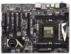
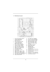
1.3 Motherboard Layout 1 ATX 12V Power Connector (ATX12V1) 21 Clear CMOS Jumper (CLRCMOS1) 2 2 x 240-pin DDR3 DIMM Slots 22 Chassis Fan Connector (CHA_FAN3) (DDR3_A1, DDR3_B1, Black) 23 ... Front Panel Audio Header 12 SPI Flash Memory (64Mb) (HD_AUDIO1, Black) 13 SB Fan Connector (SB_FAN1) 32 PCI Express 3.0 x16 Slot (PCIE4, Black) 14 Intel X79 Chipset 33 PCI Slot (PCI2, Black) 15 SATA3 Connectors (SATA3_0_1, Gray) 34 PCI Express 3.0 x16 Slot (PCIE3, Black) 16 SATA2 Connectors (SATA2_0_1, Black) 35 PCI...
1.3 Motherboard Layout 1 ATX 12V Power Connector (ATX12V1) 21 Clear CMOS Jumper (CLRCMOS1) 2 2 x 240-pin DDR3 DIMM Slots 22 Chassis Fan Connector (CHA_FAN3) (DDR3_A1, DDR3_B1, Black) 23 ... Front Panel Audio Header 12 SPI Flash Memory (64Mb) (HD_AUDIO1, Black) 13 SB Fan Connector (SB_FAN1) 32 PCI Express 3.0 x16 Slot (PCIE4, Black) 14 Intel X79 Chipset 33 PCI Slot (PCI2, Black) 15 SATA3 Connectors (SATA3_0_1, Gray) 34 PCI Express 3.0 x16 Slot (PCIE3, Black) 16 SATA2 Connectors (SATA2_0_1, Black) 35 PCI...

User Manual
Page 15
...power is switched off or the power cord is an ATX form factor (12.0" x 8.8", 30.5 x 22.4 cm) motherboard. Also remember to you install the motherboard, study the configuration of the following precautions before you handle the components. 3. Make sure to secure the mother-... injuries to use a grounded wrist strap or touch a safety grounded object before you install motherboard components or change any components. 2. Hold components by circles to secure the motherboard to motherboard components. 2.1 Screw Holes Place screws into the holes indicated by the edges and do so...
...power is switched off or the power cord is an ATX form factor (12.0" x 8.8", 30.5 x 22.4 cm) motherboard. Also remember to you install the motherboard, study the configuration of the following precautions before you handle the components. 3. Make sure to secure the mother-... injuries to use a grounded wrist strap or touch a safety grounded object before you install motherboard components or change any components. 2. Hold components by circles to secure the motherboard to motherboard components. 2.1 Screw Holes Place screws into the holes indicated by the edges and do so...

User Manual
Page 17
... alignment key 2011-Pin Socket For proper inserting, please ensure to the orient keys. Step 2-4. Step 2-3. Step 3. The cover must be placed if returning the motherboard for after service. Press down the right load lever, and secure it with the four alignment keys of the socket. Step 3-3. Flip the load plate...
... alignment key 2011-Pin Socket For proper inserting, please ensure to the orient keys. Step 2-4. Step 2-3. Step 3. The cover must be placed if returning the motherboard for after service. Press down the right load lever, and secure it with the four alignment keys of the socket. Step 3-3. Flip the load plate...

User Manual
Page 18
Then connect the CPU fan to install the screws. Align screws with the CPU fan connector on the motherboard. Connect fan header with the motherboard's holes. Below is equipped with Intel 2011Pin CPU to dissipate heat. Step 1. Apply thermal interface material onto center of the ...need to spray thermal interface material between the CPU and the heatsink to improve heat dissipation. 2.4 Installation of CPU Fan and Heatsink This motherboard is an example to illustrate the installation of IHS on side closest to the instruction manuals of your CPU fan and heatsink. Ensure ...
Then connect the CPU fan to install the screws. Align screws with the CPU fan connector on the motherboard. Connect fan header with the motherboard's holes. Below is equipped with Intel 2011Pin CPU to dissipate heat. Step 1. Apply thermal interface material onto center of the ...need to spray thermal interface material between the CPU and the heatsink to improve heat dissipation. 2.4 Installation of CPU Fan and Heatsink This motherboard is an example to illustrate the installation of IHS on side closest to the instruction manuals of your CPU fan and heatsink. Ensure ...

User Manual
Page 19
... Triple Channel Memory Technology is activated. Unlock the DIMM slot by pressing the retaining clips outward. 2.5 Installation of Memory Modules (DIMM) This motherboard provides four 240-pin DDR3 (Double Data Rate 3) DIMM slots, and supports Quad Channel Memory Technology. If only two memory modules are installed...or removing DIMMs or the system components. For quad channel configuration, you force the DIMM into a DDR3 slot; otherwise, this motherboard and DIMM may be activated. 1. Firmly insert the DIMM into the slot until the retaining clips at both ends fully snap back in ...
... Triple Channel Memory Technology is activated. Unlock the DIMM slot by pressing the retaining clips outward. 2.5 Installation of Memory Modules (DIMM) This motherboard provides four 240-pin DDR3 (Double Data Rate 3) DIMM slots, and supports Quad Channel Memory Technology. If only two memory modules are installed...or removing DIMMs or the system components. For quad channel configuration, you force the DIMM into a DDR3 slot; otherwise, this motherboard and DIMM may be activated. 1. Firmly insert the DIMM into the slot until the retaining clips at both ends fully snap back in ...

User Manual
Page 20
...chassis fan to use . Align the card connector with screws. Keep the screws for the card before you intend to motherboard chassis fan connector (CHA_FAN1, CHA_FAN2 or CHA_FAN3) when using multiple graphics cards for a PCI Express x1 lane width card...20 2.6 Expansion Slots (PCI and PCI Express Slots) There are 2 PCI slots and 4 PCI Express slots on this motherboard is already PCIE 3.0 hardware ready. Please read the documentation of the expansion card and make sure that you start the ... is already installed in a chassis). Fasten the card to install an ASRock Game Blaster card. 1.
...chassis fan to use . Align the card connector with screws. Keep the screws for the card before you intend to motherboard chassis fan connector (CHA_FAN1, CHA_FAN2 or CHA_FAN3) when using multiple graphics cards for a PCI Express x1 lane width card...20 2.6 Expansion Slots (PCI and PCI Express Slots) There are 2 PCI slots and 4 PCI Express slots on this motherboard is already PCIE 3.0 hardware ready. Please read the documentation of the expansion card and make sure that you start the ... is already installed in a chassis). Fasten the card to install an ASRock Game Blaster card. 1.

User Manual
Page 21
... should have two identical Quad SLITM-ready graphics cards that are NVIDIA® certified. 2.7 SLITM, 3-Way SLITM and Quad SLITM Operation Guide This motherboard supports NVIDIA® SLITM, 3-Way SLITM and Quad SLITM (Scalable Link Interface) technology that are NVIDIA® certified. Download the driver from NVIDIA...
... should have two identical Quad SLITM-ready graphics cards that are NVIDIA® certified. 2.7 SLITM, 3-Way SLITM and Quad SLITM Operation Guide This motherboard supports NVIDIA® SLITM, 3-Way SLITM and Quad SLITM (Scalable Link Interface) technology that are NVIDIA® certified. Download the driver from NVIDIA...

User Manual
Page 27
... website for detailed installation guide. All three CrossFireXTM components, a CrossFireXTM Ready graphics card, a CrossFireXTM Ready motherboard and a CrossFireXTM Edition co-processor graphics card, must be installed correctly to AMD graphics card manuals for ATITM...updates. 1. For other Radeon graphics card to enable CrossFireXTM feature. 2.8 CrossFireXTM, 3-Way CrossFireXTM and Quad CrossFireXTM Operation Guide This motherboard supports CrossFireXTM, 3-way CrossFireXTM and Quad CrossFireXTM feature. If a customer incorrectly configures their system they will operate as ...
... website for detailed installation guide. All three CrossFireXTM components, a CrossFireXTM Ready graphics card, a CrossFireXTM Ready motherboard and a CrossFireXTM Edition co-processor graphics card, must be installed correctly to AMD graphics card manuals for ATITM...updates. 1. For other Radeon graphics card to enable CrossFireXTM feature. 2.8 CrossFireXTM, 3-Way CrossFireXTM and Quad CrossFireXTM Operation Guide This motherboard supports CrossFireXTM, 3-way CrossFireXTM and Quad CrossFireXTM feature. If a customer incorrectly configures their system they will operate as ...

User Manual
Page 28
... the Radeon graphics card on the top of Radeon graphics cards. (CrossFire Bridge is provided with the graphics card you purchase, not bundled with this motherboard. Connect two Radeon graphics cards by installing CrossFire Bridge on CrossFire Bridge Interconnects on PCIE1 slot. (You may use the DVI to D-Sub adapter to...
... the Radeon graphics card on the top of Radeon graphics cards. (CrossFire Bridge is provided with the graphics card you purchase, not bundled with this motherboard. Connect two Radeon graphics cards by installing CrossFire Bridge on CrossFire Bridge Interconnects on PCIE1 slot. (You may use the DVI to D-Sub adapter to...

User Manual
Page 29
... connector on the Radeon graphics card on PCIE3 and PCIE4 slots. (CrossFireTM Bridge is provided with the graphics card you purchase, not bundled with this motherboard. Use one graphics card into PCIE1 slot, another graphics card to PCIE3 slot, and the other CrossFireTM Bridge to connect Radeon graphics cards on PCIE1...
... connector on the Radeon graphics card on PCIE3 and PCIE4 slots. (CrossFireTM Bridge is provided with the graphics card you purchase, not bundled with this motherboard. Use one graphics card into PCIE1 slot, another graphics card to PCIE3 slot, and the other CrossFireTM Bridge to connect Radeon graphics cards on PCIE1...

User Manual
Page 31
...' benefit, without intent to infringe. * For further information of AMD CrossFireXTM technology, please check AMD website for updates and details. 2.9 Surround Display Feature This motherboard supports Surround Display upgrade. For detailed instructions, please refer to enjoy the benefit of CrossFireXTM feature. Although you can freely enjoy the benefi...
...' benefit, without intent to infringe. * For further information of AMD CrossFireXTM technology, please check AMD website for updates and details. 2.9 Surround Display Feature This motherboard supports Surround Display upgrade. For detailed instructions, please refer to enjoy the benefit of CrossFireXTM feature. Although you can freely enjoy the benefi...

User Manual
Page 32
... port can receive the multi-direction infrared signals (top, down and front), which is used for the quick installation and usage of ASRock motherboards. If Multi-Angle CIR Receiver cannot successfully receive the infrared signals from MCE Remote Controller, please try to install it to the other... port will remain USB function. 2. Please do not use the rear USB bracket to the USB 2.0 header on ASRock motherboard. Multi-Angle CIR Receiver is compatible with CIR header. Please install it on the market. 3. Step3. Step1. Find the CIR header located...
... port can receive the multi-direction infrared signals (top, down and front), which is used for the quick installation and usage of ASRock motherboards. If Multi-Angle CIR Receiver cannot successfully receive the infrared signals from MCE Remote Controller, please try to install it to the other... port will remain USB function. 2. Please do not use the rear USB bracket to the USB 2.0 header on ASRock motherboard. Multi-Angle CIR Receiver is compatible with CIR header. Please install it on the market. 3. Step3. Step1. Find the CIR header located...

User Manual
Page 33
... of Charging the BC 1.1 standard smart devices. This motherboard provides two USB ports for proper operation. USB 2.0 port (USB0) on these two ports. 33 Please refer to charge your mobile devices via PC. USB 2.0 port (USB6) header see p.12 No. 26 With ASRock XFast Charger feature, you can freely enjoy the quick... No. 3 2. With the superb XFast Charger USB port, users are assured to Apple devices, it is the best and fastest technology to below instruction for ASRock XFast Charger: 1. In addition to enjoy the quick charging experience anytime.
... of Charging the BC 1.1 standard smart devices. This motherboard provides two USB ports for proper operation. USB 2.0 port (USB0) on these two ports. 33 Please refer to charge your mobile devices via PC. USB 2.0 port (USB6) header see p.12 No. 26 With ASRock XFast Charger feature, you can freely enjoy the quick... No. 3 2. With the superb XFast Charger USB port, users are assured to Apple devices, it is the best and fastest technology to below instruction for ASRock XFast Charger: 1. In addition to enjoy the quick charging experience anytime.

User Manual
Page 35
...interface allows up to 6.0 Gb/s data transfer rate. 2.13 Onboard Headers and Connectors Onboard headers and connectors are three USB 2.0 headers on this motherboard. Serial ATA3 Connectors (SATA3_A0: see p.12, No. 11) (SATA3_0_1: see p.12, No. 17) These four Serial ATA2 (SATA2) ...26) (9-pin USB_8_9) (see p.12 No. 25) USB_PWR P-9 P+9 GND DUMMY 1 GND P+8 P-8 USB_PWR 35 Either end of the motherboard! Besides six default USB 2.0 ports on this motherboard. Each USB 2.0 header can be connected to the SATA / SATA2 / SATA3 hard disk or the SATA2 / SATA3 connector on the I/O...
...interface allows up to 6.0 Gb/s data transfer rate. 2.13 Onboard Headers and Connectors Onboard headers and connectors are three USB 2.0 headers on this motherboard. Serial ATA3 Connectors (SATA3_A0: see p.12, No. 11) (SATA3_0_1: see p.12, No. 17) These four Serial ATA2 (SATA2) ...26) (9-pin USB_8_9) (see p.12 No. 25) USB_PWR P-9 P+9 GND DUMMY 1 GND P+8 P-8 USB_PWR 35 Either end of the motherboard! Besides six default USB 2.0 ports on this motherboard. Each USB 2.0 header can be connected to the SATA / SATA2 / SATA3 hard disk or the SATA2 / SATA3 connector on the I/O...


