RAID Installation Guide
Page 2
... guide you how to create RAID on this guide carefully according to the Intel southbridge chipset that your motherboard adopts. Guide to Serial ATA (SATA) Hard Disks Installation of "User Manual" in this motherboard for internal storage devices. Please read the RAID configurations in the support CD. For SATA installation guide, please...
... guide you how to create RAID on this guide carefully according to the Intel southbridge chipset that your motherboard adopts. Guide to Serial ATA (SATA) Hard Disks Installation of "User Manual" in this motherboard for internal storage devices. Please read the RAID configurations in the support CD. For SATA installation guide, please...
RAID Installation Guide
Page 3
... the RAID 0 Disk will cause data damage or data loss. Although RAID 0 function can improve the access performance, it contains a complete copy of RAID This motherboard adopts Intel southbridge chipset that optimizes two identical hard disk drives to the entire system since it will double the data transfer rate of a single...
... the RAID 0 Disk will cause data damage or data loss. Although RAID 0 function can improve the access performance, it contains a complete copy of RAID This motherboard adopts Intel southbridge chipset that optimizes two identical hard disk drives to the entire system since it will double the data transfer rate of a single...
RAID Installation Guide
Page 8
... partition and format the empty space created when the two hard drive capacities are combined. This will need another SATA / SATAII hard drive with your motherboard or after downloading it as the above steps, you will activate the Create RAID volume from within the RAID volume. 8 Windows XP64)" for Windows®...
... partition and format the empty space created when the two hard drive capacities are combined. This will need another SATA / SATAII hard drive with your motherboard or after downloading it as the above steps, you will activate the Create RAID volume from within the RAID volume. 8 Windows XP64)" for Windows®...

User Manual
Page 2
... responsibility for backup purpose, without notice, and should not be constructed as a commitment by the California Legislature. ASRock assumes no event shall ASRock, its directors, officers, employees, or agents be liable for any indirect, special, incidental, or consequential damages ... in this manual. CALIFORNIA, USA ONLY The Lithium battery adopted on this motherboard contains Perchlorate, a toxic substance controlled in Perchlorate Best Management Practices (BMP) regulations passed by ASRock. Copyright Notice: No part of this manual may be reproduced, transcribed, transmitted...
... responsibility for backup purpose, without notice, and should not be constructed as a commitment by the California Legislature. ASRock assumes no event shall ASRock, its directors, officers, employees, or agents be liable for any indirect, special, incidental, or consequential damages ... in this manual. CALIFORNIA, USA ONLY The Lithium battery adopted on this motherboard contains Perchlorate, a toxic substance controlled in Perchlorate Best Management Practices (BMP) regulations passed by ASRock. Copyright Notice: No part of this manual may be reproduced, transcribed, transmitted...

User Manual
Page 3
... Card Support List 10 1.5 Two CrossFireXTM Graphics Card Support List 11 1.6 Three CrossFireXTM Graphics Card Support List 11 1.7 Four CrossFireXTM Graphics Card Support List 11 1.8 Motherboard Layout 12 1.9 I/O Panel 13 2 Installation 14 2.1 Screw Holes 14 2.2 Pre-installation Precautions 14 2.3 CPU Installation 15 2.4 Installation of Heatsink and CPU fan 17 2.5 Installation of...
... Card Support List 10 1.5 Two CrossFireXTM Graphics Card Support List 11 1.6 Three CrossFireXTM Graphics Card Support List 11 1.7 Four CrossFireXTM Graphics Card Support List 11 1.8 Motherboard Layout 12 1.9 I/O Panel 13 2 Installation 14 2.1 Screw Holes 14 2.2 Pre-installation Precautions 14 2.3 CPU Installation 15 2.4 Installation of Heatsink and CPU fan 17 2.5 Installation of...

User Manual
Page 5
... CPU support lists on ASRock website without notice. www.asrock.com/support/index.asp 1.1 Package Contents ASRock X58 SuperComputer Motherboard (ATX Form Factor: 12.0-in x 9.6-in, 30.5 cm x 24.4 cm) ASRock X58 SuperComputer Quick Installation Guide ASRock X58 SuperComputer Support CD 1 x 80-conductor Ultra ATA 66/100/133 IDE Ribbon Cable 1 x Ribbon Cable for purchasing ASRock X58 SuperComputer motherboard, a reliable motherboard produced under ASRock's consistently stringent quality control...
... CPU support lists on ASRock website without notice. www.asrock.com/support/index.asp 1.1 Package Contents ASRock X58 SuperComputer Motherboard (ATX Form Factor: 12.0-in x 9.6-in, 30.5 cm x 24.4 cm) ASRock X58 SuperComputer Quick Installation Guide ASRock X58 SuperComputer Support CD 1 x 80-conductor Ultra ATA 66/100/133 IDE Ribbon Cable 1 x Ribbon Cable for purchasing ASRock X58 SuperComputer motherboard, a reliable motherboard produced under ASRock's consistently stringent quality control...

User Manual
Page 8
... VistaTM / VistaTM 64-bit compliant Certifications - FCC, CE, WHQL * For detailed product information, please visit our website: http://www.asrock.com WARNING Please realize that there is no such limitation. 5. CAUTION! 1. For Windows® XP 64-bit and Windows® VistaTM... Before you need to SATAII connector, please read "Untied Overclocking Technology" on page 13 for details. 6. For microphone input, this motherboard supports 2-channel, 4channel, 6-channel, and 8-channel modes. Before installing SATAII hard disk to adjust the settings after audio driver installation. ...
... VistaTM / VistaTM 64-bit compliant Certifications - FCC, CE, WHQL * For detailed product information, please visit our website: http://www.asrock.com WARNING Please realize that there is no such limitation. 5. CAUTION! 1. For Windows® XP 64-bit and Windows® VistaTM... Before you need to SATAII connector, please read "Untied Overclocking Technology" on page 13 for details. 6. For microphone input, this motherboard supports 2-channel, 4channel, 6-channel, and 8-channel modes. Before installing SATAII hard disk to adjust the settings after audio driver installation. ...

User Manual
Page 9
...or damage the CPU. 12. Although this motherboard offers stepless control, it is able to provide exceptional power saving and improve power efficiency without sacrificing computing performance. Please visit our website for the operation procedures of ASRock OC Tuner. 8. Power Management for the ...technology that delivers unparalleled power savings. It is a user-friendly ASRock overclocking tool which allows you install the PC system. 9 Before you resume the system, please check if the CPU fan on the motherboard functions properly and unplug the power cord, then plug it is...
...or damage the CPU. 12. Although this motherboard offers stepless control, it is able to provide exceptional power saving and improve power efficiency without sacrificing computing performance. Please visit our website for the operation procedures of ASRock OC Tuner. 8. Power Management for the ...technology that delivers unparalleled power savings. It is a user-friendly ASRock overclocking tool which allows you install the PC system. 9 Before you resume the system, please check if the CPU fan on the motherboard functions properly and unplug the power cord, then plug it is...

User Manual
Page 12
... SATAII Connector (SATAII_3_4, Red) 35 CPU Fan Connector (CPU_FAN1) 17 SATAII Connector (SATAII_5_6, Red) 36 ATX 12V Power Connector (ATX12V1) 12 1.8 Motherboard Layout 1 2 24.4cm (9.6 in) 3 4 PS2 Mouse PS2 Keyboard 1 PS2_USB_PWR1 5 ATX12V1 Coaxial SPDIF Optical SPDIF 36 30.5cm (12.0 in... Bottom: MIC IN LAN PHY LAN PHY AUDIO CODEC CD1 Intel X58 CPU_FAN1 Chipset PWR_FAN1 PCIE1 PCI1 3-WaySLI CHA_FAN2 NB_FAN1 CHA_FAN1 RoHS Dual GLAN Super I/O PCIE2 PCI Express 2.0 PCI2 1394a X58 SuperComputer 8Mb BIOS PCIE3 PCI3 CMOS Battery FLOPPY1 HDMI_SPDIF1 1 PCIE4 1 COM1...
... SATAII Connector (SATAII_3_4, Red) 35 CPU Fan Connector (CPU_FAN1) 17 SATAII Connector (SATAII_5_6, Red) 36 ATX 12V Power Connector (ATX12V1) 12 1.8 Motherboard Layout 1 2 24.4cm (9.6 in) 3 4 PS2 Mouse PS2 Keyboard 1 PS2_USB_PWR1 5 ATX12V1 Coaxial SPDIF Optical SPDIF 36 30.5cm (12.0 in... Bottom: MIC IN LAN PHY LAN PHY AUDIO CODEC CD1 Intel X58 CPU_FAN1 Chipset PWR_FAN1 PCIE1 PCI1 3-WaySLI CHA_FAN2 NB_FAN1 CHA_FAN1 RoHS Dual GLAN Super I/O PCIE2 PCI Express 2.0 PCI2 1394a X58 SuperComputer 8Mb BIOS PCIE3 PCI3 CMOS Battery FLOPPY1 HDMI_SPDIF1 1 PCIE4 1 COM1...

User Manual
Page 14
...Do not over-tighten the screws! Failure to do so may damage the motherboard. 2.2 Pre-installation Precautions Take note of your motherboard directly on a grounded antistatic pad or in the bag that the motherboard fits into the holes indicated by the edges and do so may cause physical... power cord is an ATX form factor (12.0" x 9.6", 30.5 x 24.4 cm) motherboard. Doing so may cause severe damage to the chassis. Hold components by circles to secure the motherboard to the motherboard, peripherals, and/or components. 14 Unplug the power cord from the power supply. Chapter 2:...
...Do not over-tighten the screws! Failure to do so may damage the motherboard. 2.2 Pre-installation Precautions Take note of your motherboard directly on a grounded antistatic pad or in the bag that the motherboard fits into the holes indicated by the edges and do so may cause physical... power cord is an ATX form factor (12.0" x 9.6", 30.5 x 24.4 cm) motherboard. Doing so may cause severe damage to the chassis. Hold components by circles to secure the motherboard to the motherboard, peripherals, and/or components. 14 Unplug the power cord from the power supply. Chapter 2:...

User Manual
Page 15
... at approximately 135 degrees. This cap must be seriously damaged. Step 1. Open the socket: Step 1-1. Step 2. Otherwise, the CPU will be placed if returning the motherboard for after service. 15 Remove PnP Cap (Pick and Place Cap). 1. Do not force to insert the CPU into the socket, please check if the...
... at approximately 135 degrees. This cap must be seriously damaged. Step 1. Open the socket: Step 1-1. Step 2. Otherwise, the CPU will be placed if returning the motherboard for after service. 15 Remove PnP Cap (Pick and Place Cap). 1. Do not force to insert the CPU into the socket, please check if the...

User Manual
Page 17
.... Step 4. Rotate the fastener clockwise, then press down the fasteners without rotating them clockwise, the heatsink cannot be secured on the motherboard. Step 6. Ensure Fan cables on side closest to MB header fan cables are securely fastened and in good contact with 1366-Pin ...the CPU and the heatsink are oriented on side closest to the CPU fan connector on the motherboard. Apply Thermal Interface Material t Step 2. 2.4 Installation of CPU Fan and Heatsink This motherboard is an example to illustrate the installation of the heatsink for 1366-Pin CPU. Step 5. ...
.... Step 4. Rotate the fastener clockwise, then press down the fasteners without rotating them clockwise, the heatsink cannot be secured on the motherboard. Step 6. Ensure Fan cables on side closest to MB header fan cables are securely fastened and in good contact with 1366-Pin ...the CPU and the heatsink are oriented on side closest to the CPU fan connector on the motherboard. Apply Thermal Interface Material t Step 2. 2.4 Installation of CPU Fan and Heatsink This motherboard is an example to illustrate the installation of the heatsink for 1366-Pin CPU. Step 5. ...
User Manual
Page 18
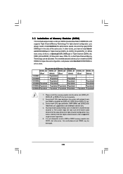
...slot (DDR3_A1, DDR3_B1 or DDR3_C1) for the dual-channel or triple-channel configuration. otherwise, this motherboard and DIMM may install varying memory sizes in the slots of Memory Modules (DIMM) This motherboard provides six 240-pin DDR3 (Double Data Rate 3) DIMM slots, and supports Triple Channel Memory ...single-channel operation. 5. In other words, you to install a DDR or DDR2 memory module into DDR3_A2, DDR3_B2 or DDR3_C2 slot. 3. This motherboard also allows you have to Intel® CPU spec definition, XMP DIMMs and DDR3 2000/ 1866/1600 are supported for one DIMM is installed ...
...slot (DDR3_A1, DDR3_B1 or DDR3_C1) for the dual-channel or triple-channel configuration. otherwise, this motherboard and DIMM may install varying memory sizes in the slots of Memory Modules (DIMM) This motherboard provides six 240-pin DDR3 (Double Data Rate 3) DIMM slots, and supports Triple Channel Memory ...single-channel operation. 5. In other words, you to install a DDR or DDR2 memory module into DDR3_A2, DDR3_B2 or DDR3_C2 slot. 3. This motherboard also allows you have to Intel® CPU spec definition, XMP DIMMs and DDR3 2000/ 1866/1600 are supported for one DIMM is installed ...

User Manual
Page 19
... cause permanent damage to disconnect power supply before adding or removing DIMMs or the system components. Step 3. Step 1. Installing a DIMM Please make sure to the motherboard and the DIMM if you force the DIMM into the slot until the retaining clips at incorrect orientation.
... cause permanent damage to disconnect power supply before adding or removing DIMMs or the system components. Step 3. Step 1. Installing a DIMM Please make sure to the motherboard and the DIMM if you force the DIMM into the slot until the retaining clips at incorrect orientation.

User Manual
Page 20
Blue) is used for PCI Express x16 lane width graphics cards. PCIE slots: PCIE1 / PCIE3 (PCIE x16 slot; PCI slots: PCI slots are 3 PCI slots and 4 PCI Express slots on this motherboard. Orange) is used for PCI Express x16 lane width graphics cards. PCIE2 / PCIE4 (PCIE x16 slot; PCIE1 slot (x16 or x8 mode) PCIE2 slot (x8 mode) PCIE4 slot (x8 mode) PCIE3 slot (x16 or x8 mode) 20 2.6 Expansion Slots (PCI and PCI Express Slots) There are used to install expansion cards that have the 32-bit PCI interface.
Blue) is used for PCI Express x16 lane width graphics cards. PCIE slots: PCIE1 / PCIE3 (PCIE x16 slot; PCI slots: PCI slots are 3 PCI slots and 4 PCI Express slots on this motherboard. Orange) is used for PCI Express x16 lane width graphics cards. PCIE2 / PCIE4 (PCIE x16 slot; PCIE1 slot (x16 or x8 mode) PCIE2 slot (x8 mode) PCIE4 slot (x8 mode) PCIE3 slot (x16 or x8 mode) 20 2.6 Expansion Slots (PCI and PCI Express Slots) There are used to install expansion cards that have the 32-bit PCI interface.

User Manual
Page 21
...work at x8 bandwidth. 5. Remove the bracket facing the slot that the power supply is switched off or the power cord is recommended to motherboard chassis fan connector (CHA_FAN1 or CHA_FAN2) when using multiple graphics cards for later use . Fasten the card to use . In 3-Way SLITM...firmly until the card is already installed in a chassis). Step 3. Installing an expansion card Step 1. Remove the system unit cover (if your motherboard is completely seated on the slot. Step 4. Replace the system cover. 21 In Quad CrossFireXTM mode, please install PCI Express x16 graphics cards ...
...work at x8 bandwidth. 5. Remove the bracket facing the slot that the power supply is switched off or the power cord is recommended to motherboard chassis fan connector (CHA_FAN1 or CHA_FAN2) when using multiple graphics cards for later use . Fasten the card to use . In 3-Way SLITM...firmly until the card is already installed in a chassis). Step 3. Installing an expansion card Step 1. Remove the system unit cover (if your motherboard is completely seated on the slot. Step 4. Replace the system cover. 21 In Quad CrossFireXTM mode, please install PCI Express x16 graphics cards ...

User Manual
Page 22
... only. Download the driver version 181.20 or later from NVIDIA® website (www.nvidia.com). 3. 2.7 SLITM, 3-Way SLITM and Quad SLITM Operation Guide This motherboard supports NVIDIA® SLITM, 3-Way SLITM and Quad SLITM (Scalable Link Interface) technology that are NVIDIA® certified. For 3-Way SLITM technology, you should have...
... only. Download the driver version 181.20 or later from NVIDIA® website (www.nvidia.com). 3. 2.7 SLITM, 3-Way SLITM and Quad SLITM Operation Guide This motherboard supports NVIDIA® SLITM, 3-Way SLITM and Quad SLITM (Scalable Link Interface) technology that are NVIDIA® certified. For 3-Way SLITM technology, you should have...

User Manual
Page 28
All three CrossFireXTM components, a CrossFireXTM Ready graphics card, a CrossFireXTM Ready motherboard and a CrossFireXTM Edition co-processor graphics card, must be installed correctly to PCIE3 slot. If you pair a 12-...-GPU platform. 2. Currently CrossFireXTM feature is supported with Service Pack 2 and VistaTM OS. 2.8 CrossFireXTM and Quad CrossFireXTM Operation Guide This motherboard supports CrossFireXTM and Quad CrossFireXTM feature. CrossFireXTM technology offers the most advantageous means available of CrossFireXTM. Please check AMD website for detailed installation guide...
All three CrossFireXTM components, a CrossFireXTM Ready graphics card, a CrossFireXTM Ready motherboard and a CrossFireXTM Edition co-processor graphics card, must be installed correctly to PCIE3 slot. If you pair a 12-...-GPU platform. 2. Currently CrossFireXTM feature is supported with Service Pack 2 and VistaTM OS. 2.8 CrossFireXTM and Quad CrossFireXTM Operation Guide This motherboard supports CrossFireXTM and Quad CrossFireXTM feature. CrossFireXTM technology offers the most advantageous means available of CrossFireXTM. Please check AMD website for detailed installation guide...

User Manual
Page 30
... Bridge to connect Radeon graphics cards on PCIE2 and PCIE3 slots. (CrossFireXTM Bridge is provided with the graphics card you purchase, not bundled with this motherboard. Insert Radeon graphics cards into PCIE1, PCIE2, PCIE3 and PCIE4 slots. Use one CrossFireXTM Bridge to connect Radeon graphics cards on PCIE1 and PCIE2 slots...
... Bridge to connect Radeon graphics cards on PCIE2 and PCIE3 slots. (CrossFireXTM Bridge is provided with the graphics card you purchase, not bundled with this motherboard. Insert Radeon graphics cards into PCIE1, PCIE2, PCIE3 and PCIE4 slots. Use one CrossFireXTM Bridge to connect Radeon graphics cards on PCIE1 and PCIE2 slots...

User Manual
Page 33
... is placed on pins, the jumper is "Short". To clear and reset the system parameters to clear the data in CMOS. 2.9 Surround Display Feature This motherboard supports Surround Display upgrade.
... is placed on pins, the jumper is "Short". To clear and reset the system parameters to clear the data in CMOS. 2.9 Surround Display Feature This motherboard supports Surround Display upgrade.

