
User Manual
Page 12
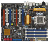
1.8 Motherboard Layout 1 2 24.4cm (9.6 in) 3 4 PS2 Mouse PS2 Keyboard 1 PS2_USB_PWR1... Center: FRONT Bottom: MIC IN LAN PHY AUDIO CODEC CD1 Intel X58 CPU_FAN1 Chipset PWR_FAN1 PCIE1 PCI1 3-WaySLI CHA_FAN2 NB_FAN1 CHA_FAN1 RoHS Super I/O PCIE2 PCI2 X58 Deluxe PCI Express 2.0 1394a 8Mb BIOS PCIE3 PCI3 CMOS Battery FLOPPY1 HDMI_SPDIF1 ... 1 USB6_7 1 USB8_9 6 7 8 9 10 11 12 13 14 15 16 17 1 PS2_USB_PWR1 Jumper 18 Chassis Speaker Header 2 1366-Pin CPU Socket (SPEAKER 1, Purple) 3 North Bridge Controller 19 USB 2.0 Header (USB10, Blue) 4 3 x 240-pin DDR3 DIMM Slots 20...
1.8 Motherboard Layout 1 2 24.4cm (9.6 in) 3 4 PS2 Mouse PS2 Keyboard 1 PS2_USB_PWR1... Center: FRONT Bottom: MIC IN LAN PHY AUDIO CODEC CD1 Intel X58 CPU_FAN1 Chipset PWR_FAN1 PCIE1 PCI1 3-WaySLI CHA_FAN2 NB_FAN1 CHA_FAN1 RoHS Super I/O PCIE2 PCI2 X58 Deluxe PCI Express 2.0 1394a 8Mb BIOS PCIE3 PCI3 CMOS Battery FLOPPY1 HDMI_SPDIF1 ... 1 USB6_7 1 USB8_9 6 7 8 9 10 11 12 13 14 15 16 17 1 PS2_USB_PWR1 Jumper 18 Chassis Speaker Header 2 1366-Pin CPU Socket (SPEAKER 1, Purple) 3 North Bridge Controller 19 USB 2.0 Header (USB10, Blue) 4 3 x 240-pin DDR3 DIMM Slots 20...

User Manual
Page 15
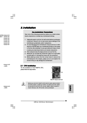
...position at approximately 135 degrees. Otherwise, the CPU will be placed if returning the motherboard for after service. 15 Step 1. It is found. Disengaging the lever by depressing down and out on the socket. Step 2. This cap must be seriously damaged. Rotate the load lever to fully...PnP cap. 2. 2.3 CPU Installation For the installation of Intel 1366-Pin CPU, please follow the steps below. Load Plate Contact Array Socket Body Load Lever 1366-Pin Socket Overview Before you insert the 1366-Pin CPU into the socket if above situation is recommended to use the cap tab to ...
...position at approximately 135 degrees. Otherwise, the CPU will be placed if returning the motherboard for after service. 15 Step 1. It is found. Disengaging the lever by depressing down and out on the socket. Step 2. This cap must be seriously damaged. Rotate the load lever to fully...PnP cap. 2. 2.3 CPU Installation For the installation of Intel 1366-Pin CPU, please follow the steps below. Load Plate Contact Array Socket Body Load Lever 1366-Pin Socket Overview Before you insert the 1366-Pin CPU into the socket if above situation is recommended to use the cap tab to ...

User Manual
Page 17
Ensure that supports Intel 1366-Pin CPU. Below is equipped with 1366-Pin socket that the CPU and the heatsink are oriented on side closest to the CPU fan connector on the motherboard (CPU_FAN1, see page 12, No. 35). Connect fan header with the CPU fan connector on ...Place the heatsink onto the socket. Secure excess cable with tie-wrap to ensure cable does not interfere with Intel 1366-Pin CPU to dissipate heat. Before you installed the heatsink, you press down on the motherboard. 2.4 Installation of CPU Fan and Heatsink This motherboard is an example to illustrate...
Ensure that supports Intel 1366-Pin CPU. Below is equipped with 1366-Pin socket that the CPU and the heatsink are oriented on side closest to the CPU fan connector on the motherboard (CPU_FAN1, see page 12, No. 35). Connect fan header with the CPU fan connector on ...Place the heatsink onto the socket. Secure excess cable with tie-wrap to ensure cable does not interfere with Intel 1366-Pin CPU to dissipate heat. Before you installed the heatsink, you press down on the motherboard. 2.4 Installation of CPU Fan and Heatsink This motherboard is an example to illustrate...

Quick Installation Guide
Page 2
...10 3 x 240-pin DDR3 DIMM Slots (HDMI_SPDIF1, Yellow) (Triple Channel: DDR3_A2, DDR3_B2, DDR3_C2 29 PCI Express x16 Slot (PCIE4, Orange) ; Motherboard Layout English 1 PS2_USB_PWR1 Jumper 18 Chassis Speaker Header 2 1366-Pin CPU Socket (SPEAKER 1, Purple) 3 North Bridge Controller 19 USB 2.0 Header (USB10, Blue) 4 3 x 240-pin DDR3 DIMM Slots 20 South Bridge Controller ..., Red) (HD_AUDIO1, Lime) 16 SATAII Connector (SATAII_3_4, Red) 35 CPU Fan Connector (CPU_FAN1) 17 SATAII Connector (SATAII_5_6, Red) 36 ATX 12V Power Connector (ATX12V1) 2 ASRock X58 Deluxe Motherboard
...10 3 x 240-pin DDR3 DIMM Slots (HDMI_SPDIF1, Yellow) (Triple Channel: DDR3_A2, DDR3_B2, DDR3_C2 29 PCI Express x16 Slot (PCIE4, Orange) ; Motherboard Layout English 1 PS2_USB_PWR1 Jumper 18 Chassis Speaker Header 2 1366-Pin CPU Socket (SPEAKER 1, Purple) 3 North Bridge Controller 19 USB 2.0 Header (USB10, Blue) 4 3 x 240-pin DDR3 DIMM Slots 20 South Bridge Controller ..., Red) (HD_AUDIO1, Lime) 16 SATAII Connector (SATAII_3_4, Red) 35 CPU Fan Connector (CPU_FAN1) 17 SATAII Connector (SATAII_5_6, Red) 36 ATX 12V Power Connector (ATX12V1) 2 ASRock X58 Deluxe Motherboard

Quick Installation Guide
Page 5
Intel® Socket 1366 CoreTM i7 Processor Extreme Edition / CoreTM i7 Processor Supports Intel® Dynamic Speed Technology - Supports EM64T CPU - Supports Intel® Extreme Memory Profile (XMP) - 4 x PCI ... USB 2.0 Ports - 1 x Powered eSATAII/USB Connector - 1 x RJ-45 LAN Port with LED (ACT/LINK LED and SPEED LED) 5 ASRock X58 Deluxe Motherboard English Supports Hyper-Threading Technology (see CAUTION 3) - 6 x DDR3 DIMM slots - Northbridge: Intel® X58 - DAC with Content Protection - Supports Wake-On-LAN I /O - Supports DDR3 2000(OC)/1866(OC)/1600(OC)/1333(OC)/1066...
Intel® Socket 1366 CoreTM i7 Processor Extreme Edition / CoreTM i7 Processor Supports Intel® Dynamic Speed Technology - Supports EM64T CPU - Supports Intel® Extreme Memory Profile (XMP) - 4 x PCI ... USB 2.0 Ports - 1 x Powered eSATAII/USB Connector - 1 x RJ-45 LAN Port with LED (ACT/LINK LED and SPEED LED) 5 ASRock X58 Deluxe Motherboard English Supports Hyper-Threading Technology (see CAUTION 3) - 6 x DDR3 DIMM slots - Northbridge: Intel® X58 - DAC with Content Protection - Supports Wake-On-LAN I /O - Supports DDR3 2000(OC)/1866(OC)/1600(OC)/1333(OC)/1066...
Quick Installation Guide
Page 11
... grounded object before you insert the 1366-Pin CPU into the screw holes to secure the motherboard to the motherboard, peripherals, and/or components. 2. Also remember to static electricity, NEVER place your motherboard directly on the socket. Otherwise, the CPU will be ...please do not touch the ICs. 4. Whenever you install motherboard components or change any component. When placing screws into the socket, please check if the CPU surface is unclean or if there is found. English 11 ASRock X58 Deluxe Motherboard 00PRO Catalyst 8.9 00XT Catalyst 8.9 Catalyst 8.9 Catalyst 8.9 ...
... grounded object before you insert the 1366-Pin CPU into the screw holes to secure the motherboard to the motherboard, peripherals, and/or components. 2. Also remember to static electricity, NEVER place your motherboard directly on the socket. Otherwise, the CPU will be ...please do not touch the ICs. 4. Whenever you install motherboard components or change any component. When placing screws into the socket, please check if the CPU surface is unclean or if there is found. English 11 ASRock X58 Deluxe Motherboard 00PRO Catalyst 8.9 00XT Catalyst 8.9 Catalyst 8.9 Catalyst 8.9 ...

Quick Installation Guide
Page 12
...Step 2. black line black line English 1. This cap must be placed if returning the motherboard for after service. Insert the 1366-Pin CPU: Step 3-1. Locate Pin1 and the two orientation key notches. Open the socket: Step 1-1. Disengaging the lever by the edges where are marked with IHS (Integrated Heat...Step 3. Step 1. Rotate the load plate to match the two orientation key notches of the CPU with the two alignment keys of the socket. 12 ASRock X58 Deluxe Motherboard Remove PnP Cap (Pick and Place Cap). It is recommended to use the cap tab to clear retention tab. Step 3-2. Step 1-3. Hold...
...Step 2. black line black line English 1. This cap must be placed if returning the motherboard for after service. Insert the 1366-Pin CPU: Step 3-1. Locate Pin1 and the two orientation key notches. Open the socket: Step 1-1. Disengaging the lever by the edges where are marked with IHS (Integrated Heat...Step 3. Step 1. Rotate the load plate to match the two orientation key notches of the CPU with the two alignment keys of the socket. 12 ASRock X58 Deluxe Motherboard Remove PnP Cap (Pick and Place Cap). It is recommended to use the cap tab to clear retention tab. Step 3-2. Step 1-3. Hold...

Quick Installation Guide
Page 13
... to the instruction manuals of your CPU fan and heatsink. Step 4-3. Apply thermal interface material onto center of the heatsink for 1366-Pin CPU. Ensure fan cables are oriented on fastener caps with thumb to ensure cable does not interfere with tie-wrap to...cable with fan operation or contact other components. 13 ASRock X58 Deluxe Motherboard English Below is within the socket and properly mated to the CPU fan connector on the motherboard (CPU_FAN1, see page 2, No. 35). Step 6. Carefully place the CPU into the socket by using a purely vertical motion. While pressing down...
... to the instruction manuals of your CPU fan and heatsink. Step 4-3. Apply thermal interface material onto center of the heatsink for 1366-Pin CPU. Ensure fan cables are oriented on fastener caps with thumb to ensure cable does not interfere with tie-wrap to...cable with fan operation or contact other components. 13 ASRock X58 Deluxe Motherboard English Below is within the socket and properly mated to the CPU fan connector on the motherboard (CPU_FAN1, see page 2, No. 35). Step 6. Carefully place the CPU into the socket by using a purely vertical motion. While pressing down...


