RAID Installation Guide
Page 2
...) hard disks with RAID functions, including RAID 0, RAID 1, RAID 10, RAID 5, and Intel Matrix Storage. Guide to Serial ATA (SATA) Hard Disks Installation of "User Manual" in this motherboard for internal storage devices. 1. Please read the RAID configurations in the support CD.
...) hard disks with RAID functions, including RAID 0, RAID 1, RAID 10, RAID 5, and Intel Matrix Storage. Guide to Serial ATA (SATA) Hard Disks Installation of "User Manual" in this motherboard for internal storage devices. 1. Please read the RAID configurations in the support CD.

User Manual
Page 1
All rights reserved. 1 X58 Deluxe User Manual Version 1.1 Published April 2009 Copyright©2009 ASRock INC.
All rights reserved. 1 X58 Deluxe User Manual Version 1.1 Published April 2009 Copyright©2009 ASRock INC.

User Manual
Page 2
... arising from any defect or error in this device may apply, see www.dtsc.ca.gov/hazardouswaste/perchlorate" ASRock Website: http://www.asrock.com 2 Copyright Notice: No part of this manual may be reproduced, transcribed, transmitted, or translated in any language, in any form or by any means,...purchaser for identification or explanation and to the owners' benefit, without intent to infringe. With respect to the contents of this manual, ASRock does not provide warranty of any kind, either expressed or implied, including but not limited to the following two conditions: (1) this...
... arising from any defect or error in this device may apply, see www.dtsc.ca.gov/hazardouswaste/perchlorate" ASRock Website: http://www.asrock.com 2 Copyright Notice: No part of this manual may be reproduced, transcribed, transmitted, or translated in any language, in any form or by any means,...purchaser for identification or explanation and to the owners' benefit, without intent to infringe. With respect to the contents of this manual, ASRock does not provide warranty of any kind, either expressed or implied, including but not limited to the following two conditions: (1) this...

User Manual
Page 5
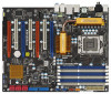
... information of the motherboard and step-by-step guide to this manual will be updated, the content of this motherboard, please visit our website for specific information about the model you for a 3.5-in , 30.5 cm x 24.4 cm) ASRock X58 Deluxe Quick Installation Guide ASRock X58 Deluxe Support CD 1 x 80-conductor Ultra ATA 66/100/133 IDE Ribbon...
... information of the motherboard and step-by-step guide to this manual will be updated, the content of this motherboard, please visit our website for specific information about the model you for a 3.5-in , 30.5 cm x 24.4 cm) ASRock X58 Deluxe Quick Installation Guide ASRock X58 Deluxe Support CD 1 x 80-conductor Ultra ATA 66/100/133 IDE Ribbon...

User Manual
Page 17
... to spray thermal interface material between the CPU and the heatsink to ensure cable does not interfere with Intel 1366-Pin CPU to the instruction manuals of your CPU fan and heatsink. Repeat with the motherboard throughholes. Secure excess cable with thumb to the CPU fan connector on side closest to...
... to spray thermal interface material between the CPU and the heatsink to ensure cable does not interfere with Intel 1366-Pin CPU to the instruction manuals of your CPU fan and heatsink. Repeat with the motherboard throughholes. Secure excess cable with thumb to the CPU fan connector on side closest to...
User Manual
Page 28
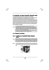
... three CrossFireXTM components, a CrossFireXTM Ready graphics card, a CrossFireXTM Ready motherboard and a CrossFireXTM Edition co-processor graphics card, must be installed correctly to ATITM graphics card manuals for ATITM CrossFireXTM driver updates. 1. Step 1. If you pair a 12-pipe CrossFireXTM Edition card with Windows® VistaTM OS only. Currently CrossFireXTM feature is supported...
... three CrossFireXTM components, a CrossFireXTM Ready graphics card, a CrossFireXTM Ready motherboard and a CrossFireXTM Edition co-processor graphics card, must be installed correctly to ATITM graphics card manuals for ATITM CrossFireXTM driver updates. 1. Step 1. If you pair a 12-pipe CrossFireXTM Edition card with Windows® VistaTM OS only. Currently CrossFireXTM feature is supported...

User Manual
Page 36
... jack detection", and save the change by clicking "OK". G. MIC_RET and OUT_RET are for AC'97 audio panel. 1. Please follow the instruction in our manual and chassis manual to the "Front Mic" Tab in "Front Mic" of "Playback" portion. C. Set the Front Panel Control option from [Auto] to OUT2_L. Enter Windows system...
... jack detection", and save the change by clicking "OK". G. MIC_RET and OUT_RET are for AC'97 audio panel. 1. Please follow the instruction in our manual and chassis manual to the "Front Mic" Tab in "Front Mic" of "Playback" portion. C. Set the Front Panel Control option from [Auto] to OUT2_L. Enter Windows system...

User Manual
Page 39
...and the VGA card may cause permanent damage to the HDMI_SPDIF connector of PCI Express VGA card. Please refer to the VGA card user manual for detailed connection procedures. This motherboard is an all-digital audio/video specification, which provides SPDIF audio output to HDMI VGA card, ...HDMI function on HDMI VGA card to the fan connector of the HDMI VGA card you install. Install HDMI VGA card driver to the user manual of connecting HDMI_SPDIF cable to HDMI device, such as a digital television (DTV). Step 1. Please choose the appropriate white end according to this ...
...and the VGA card may cause permanent damage to the HDMI_SPDIF connector of PCI Express VGA card. Please refer to the VGA card user manual for detailed connection procedures. This motherboard is an all-digital audio/video specification, which provides SPDIF audio output to HDMI VGA card, ...HDMI function on HDMI VGA card to the fan connector of the HDMI VGA card you install. Install HDMI VGA card driver to the user manual of connecting HDMI_SPDIF cable to HDMI device, such as a digital television (DTV). Step 1. Please choose the appropriate white end according to this ...

User Manual
Page 43
... which cannot support Hot Plug function, will cause the HDD damage and data loss. Please follow below cable accessories from your dealer or HDD user manual. Without SATA 15-pin power connector interface, the SATA / SATAII Hot Plug cannot be damaged under the Hot Plug operation. 3. 2.16 SATA ...is indicated in RAID / AHCI mode. SATA data cable (Red) B. Please make sure the SATA / SATAII driver is available on our website: www.asrock.com 2. A. 7-pin SATA data cable B. Even some SATA / SATAII HDDs provide both SATA 15-pin power connector and IDE 1x4-pin conventional power ...
... which cannot support Hot Plug function, will cause the HDD damage and data loss. Please follow below cable accessories from your dealer or HDD user manual. Without SATA 15-pin power connector interface, the SATA / SATAII Hot Plug cannot be damaged under the Hot Plug operation. 3. 2.16 SATA ...is indicated in RAID / AHCI mode. SATA data cable (Red) B. Please make sure the SATA / SATAII driver is available on our website: www.asrock.com 2. A. 7-pin SATA data cable B. Even some SATA / SATAII HDDs provide both SATA 15-pin power connector and IDE 1x4-pin conventional power ...

User Manual
Page 50
... untied during overclocking, FSB enjoys better margin due to fixed PCI / PCIE buses. Enter BIOS SETUP UTILITY Advanced screen IDE Configuration. page, please insert the ASRock Support CD into your optical drive, and click the "Load Driver" button on the left on your system, and follow below steps. B. Using SATA / SATAII... page 8 for the possible overclocking risk before you enable Untied Overclocking function, please enter "Overclock Mode" option of BIOS setup to set the option to [Manual]. Before you apply Untied Overclocking Technology. 50
... untied during overclocking, FSB enjoys better margin due to fixed PCI / PCIE buses. Enter BIOS SETUP UTILITY Advanced screen IDE Configuration. page, please insert the ASRock Support CD into your optical drive, and click the "Load Driver" button on the left on your system, and follow below steps. B. Using SATA / SATAII... page 8 for the possible overclocking risk before you enable Untied Overclocking function, please enter "Overclock Mode" option of BIOS setup to set the option to [Manual]. Before you apply Untied Overclocking Technology. 50

User Manual
Page 58
... item should always be above [3200MHz]. The default value is [Auto]. 58 The default value is [Auto]. Configuration options: [Auto], [Manual], [I .O.T.] (Intelligent Overclocking Technology), the system will automatically enable the overclocking function when your CPU is [800MHz (DDR3 1600)], uncore frequency ...should be at least double of DRAM frequency. Therefore, you select [Manual], Untied Overclocking function is [Auto]. Boot Failure Guard Enable or disable the feature of Untied Overclocking Technology. If you are ...
... item should always be above [3200MHz]. The default value is [Auto]. 58 The default value is [Auto]. Configuration options: [Auto], [Manual], [I .O.T.] (Intelligent Overclocking Technology), the system will automatically enable the overclocking function when your CPU is [800MHz (DDR3 1600)], uncore frequency ...should be at least double of DRAM frequency. Therefore, you select [Manual], Untied Overclocking function is [Auto]. Boot Failure Guard Enable or disable the feature of Untied Overclocking Technology. If you are ...

User Manual
Page 60
... the number of DRAM clocks for TWTR. Configuration options: Configuration options: [Auto], [2] to select CPU Voltage. Configuration options: [Auto] and [Manual]. DRAM tFAW This controls the number of DRAM clocks for TFAW. The default value is [Auto]. The default value is [Auto]. Configuration options:... PCIE Voltage CPU PLL Voltage [Auto] [Auto] [Auto] [Auto] [Auto] [Auto] [Auto] [Auto] [Auto] [Auto] Options Auto Manual +F1 F9 F10 ESC Select Screen Select Item Change Option General Help Load Defaults Save and Exit Exit v02.54 (C) Copyright 1985-2005, American Megatrends...
... the number of DRAM clocks for TWTR. Configuration options: Configuration options: [Auto], [2] to select CPU Voltage. Configuration options: [Auto] and [Manual]. DRAM tFAW This controls the number of DRAM clocks for TFAW. The default value is [Auto]. The default value is [Auto]. Configuration options:... PCIE Voltage CPU PLL Voltage [Auto] [Auto] [Auto] [Auto] [Auto] [Auto] [Auto] [Auto] [Auto] [Auto] Options Auto Manual +F1 F9 F10 ESC Select Screen Select Item Change Option General Help Load Defaults Save and Exit Exit v02.54 (C) Copyright 1985-2005, American Megatrends...

Quick Installation Guide
Page 4
.... More detailed information of this manual occur, the updated version will be subject to quality and endurance. This Quick Installation Guide contains introduction of this motherboard, please visit our website for specific information about the model you for a 3.5-in , 30.5 cm x 24.4 cm) ASRock X58 Deluxe Quick Installation Guide ASRock X58 Deluxe Support CD 1 x 80-conductor Ultra...
.... More detailed information of this manual occur, the updated version will be subject to quality and endurance. This Quick Installation Guide contains introduction of this motherboard, please visit our website for specific information about the model you for a 3.5-in , 30.5 cm x 24.4 cm) ASRock X58 Deluxe Quick Installation Guide ASRock X58 Deluxe Support CD 1 x 80-conductor Ultra...

Quick Installation Guide
Page 7
... the installation guide of memory modules on page 3 for the operation procedures of "User Manual" in the support CD to read the "SATAII Hard Disk Setup Guide" on page 35 for proper installation. 4. ASRock website: http://www.asrock.com English 7 ASRock X58 Deluxe Motherboard It is no such limitation. 5. Please check the table on page 14...
... the installation guide of memory modules on page 3 for the operation procedures of "User Manual" in the support CD to read the "SATAII Hard Disk Setup Guide" on page 35 for proper installation. 4. ASRock website: http://www.asrock.com English 7 ASRock X58 Deluxe Motherboard It is no such limitation. 5. Please check the table on page 14...

Quick Installation Guide
Page 13
...press down on side closest to the orient keys. et Step 5. Secure excess cable with fan operation or contact other components. 13 ASRock X58 Deluxe Motherboard English Rotate the load plate onto the IHS. Step 1. Step 3. Step 3-4. Apply thermal interface material onto center of your CPU... not interfere with tie-wrap to install and lock. Step 6. Step 4-3. Verify that the CPU is an example to the instruction manuals of IHS on the motherboard. Align fasteners with remaining fasteners. Close the socket: Step 4-1. Step 4. Secure load lever with the ...
...press down on side closest to the orient keys. et Step 5. Secure excess cable with fan operation or contact other components. 13 ASRock X58 Deluxe Motherboard English Rotate the load plate onto the IHS. Step 1. Step 3. Step 3-4. Apply thermal interface material onto center of your CPU... not interfere with tie-wrap to install and lock. Step 6. Step 4-3. Verify that the CPU is an example to the instruction manuals of IHS on the motherboard. Align fasteners with remaining fasteners. Close the socket: Step 4-1. Step 4. Secure load lever with the ...

Quick Installation Guide
Page 23
... Cards Different CrossFireXTM cards may require different methods to ATITM graphics card manuals for ATITM CrossFireXTM driver updates. 1. Please check AMD website for detailed installation guide. Insert one Radeon graphics card into PCIE1 slot and the other CrossFireXTM cards that the cards are properly seated on the slots. English 23 ASRock X58 Deluxe Motherboard
... Cards Different CrossFireXTM cards may require different methods to ATITM graphics card manuals for ATITM CrossFireXTM driver updates. 1. Please check AMD website for detailed installation guide. Insert one Radeon graphics card into PCIE1 slot and the other CrossFireXTM cards that the cards are properly seated on the slots. English 23 ASRock X58 Deluxe Motherboard

Quick Installation Guide
Page 30
... [Enabled]. B. D. Set the Front Panel Control option from [Auto] to MIC2_L. To activate the front mic. Please follow the instruction in our manual and chassis manual to this header. 30 ASRock X58 Deluxe Motherboard You don't need to connect them for HD audio panel only. Click "Set Default Device" to hear your system. 2. English Chassis...
... [Enabled]. B. D. Set the Front Panel Control option from [Auto] to MIC2_L. To activate the front mic. Please follow the instruction in our manual and chassis manual to this header. 30 ASRock X58 Deluxe Motherboard You don't need to connect them for HD audio panel only. Click "Set Default Device" to hear your system. 2. English Chassis...

Quick Installation Guide
Page 35
... the Main Menu automatically if "AUTORUN" is untied during the Power-On-Self-Test (POST) to display the menus. 35 ASRock X58 Deluxe Motherboard English It is designed to [Manual]. Software Support CD information This motherboard supports various Microsoft® Windows® operating systems: XP / XP 64-bit / VistaTM...overclocking, but PCI / PCIE buses are in the Support CD. 4. For the detailed information about BIOS Setup, please refer to the User Manual (PDF file) contained in the fixed mode so that came with its various sub-menus and to fixed PCI / PCIE buses. The Support...
... the Main Menu automatically if "AUTORUN" is untied during the Power-On-Self-Test (POST) to display the menus. 35 ASRock X58 Deluxe Motherboard English It is designed to [Manual]. Software Support CD information This motherboard supports various Microsoft® Windows® operating systems: XP / XP 64-bit / VistaTM...overclocking, but PCI / PCIE buses are in the Support CD. 4. For the detailed information about BIOS Setup, please refer to the User Manual (PDF file) contained in the fixed mode so that came with its various sub-menus and to fixed PCI / PCIE buses. The Support...
