RAID Installation Guide
Page 2
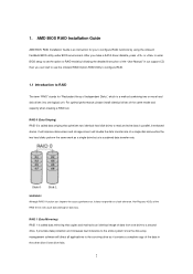
... the "User Manual" in the other drive if one logical unit. AMD BIOS RAID Installation Guide AMD BIOS RAID Installation Guide is a method combining two or more hard disk drives into one drive fails. 2 After you can improve the access performance, it does not provide any HDDs of the RAID 0 Disk will double the data transfer rate of the same model and capacity when creating a RAID set the option to RAID mode by using the onboard FastBuild BIOS utility under BIOS environment...
... the "User Manual" in the other drive if one logical unit. AMD BIOS RAID Installation Guide AMD BIOS RAID Installation Guide is a method combining two or more hard disk drives into one drive fails. 2 After you can improve the access performance, it does not provide any HDDs of the RAID 0 Disk will double the data transfer rate of the same model and capacity when creating a RAID set the option to RAID mode by using the onboard FastBuild BIOS utility under BIOS environment...
RAID Installation Guide
Page 8
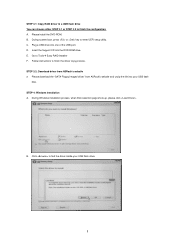
... of the USB port. B. Plug a USB drive into the DVD-ROM drive. STEP 3.1: Copy RAID driver to a USB flash drive You can choose either STEP 3.1 or STEP 3.2 to Tools Easy RAID Installer F. Please download the "SATA Floppy Imaged driver" from ASRock's website A. Go to finish the configuration. STEP 3.2: Download driver from ASRock's website and unzip the file into your USB flash drive. 8 A. During Windows installation process, when Disk selection page show up, please click . B. During system boot, press or key to finish...
... of the USB port. B. Plug a USB drive into the DVD-ROM drive. STEP 3.1: Copy RAID driver to a USB flash drive You can choose either STEP 3.1 or STEP 3.2 to Tools Easy RAID Installer F. Please download the "SATA Floppy Imaged driver" from ASRock's website A. Go to finish the configuration. STEP 3.2: Download driver from ASRock's website and unzip the file into your USB flash drive. 8 A. During Windows installation process, when Disk selection page show up, please click . B. During system boot, press or key to finish...

RAID Installation Guide
Page 14
Please install the DVD-ROM. B. Plug a USB drive into the DVD-ROM drive. Insert the Support CD into one of the USB port. Go to finish the driver copy process. Follow instructions to Tools Easy RAID Installer F. Please download the "SATA Floppy Imaged driver" from ASRock's website A. K. Click to save to enter UEFI setup utility. A. Select "Create Array". During system boot, press or key to exit. STEP 2.1: Copy RAID driver to a USB flash drive You can choose either STEP2.1 or STEP2.2 to...
Please install the DVD-ROM. B. Plug a USB drive into the DVD-ROM drive. Insert the Support CD into one of the USB port. Go to finish the driver copy process. Follow instructions to Tools Easy RAID Installer F. Please download the "SATA Floppy Imaged driver" from ASRock's website A. K. Click to save to enter UEFI setup utility. A. Select "Create Array". During system boot, press or key to exit. STEP 2.1: Copy RAID driver to a USB flash drive You can choose either STEP2.1 or STEP2.2 to...
RAID Installation Guide
Page 15
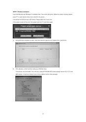
During Windows installation process, when Disk selection page show up, please click . Three drivers must be loaded. Using SATA/NVMe RAID driver package (version 9.2.0.127) from . It might look different when using a different version driver package. 15 Then restart the system. Click to boot from AMD website. It should list the USB drive as a UEFI device. This is shown in this point, then please open the boot menu that is the first. A. B. While...
During Windows installation process, when Disk selection page show up, please click . Three drivers must be loaded. Using SATA/NVMe RAID driver package (version 9.2.0.127) from . It might look different when using a different version driver package. 15 Then restart the system. Click to boot from AMD website. It should list the USB drive as a UEFI device. This is shown in this point, then please open the boot menu that is the first. A. B. While...

Quick Installation Guide
Page 5
... 7 AMD FAN LED Header (AMD_FAN_LED1) 8 2 x 288-pin DDR4 DIMM Slots (DDR4_A2, DDR4_B2) 9 ATX Power Connector (ATXPWR1) 10 USB 3.2 Gen1 Header (USB3_7_8) 11 Chassis / Waterpump Fan Connector (CHA_FAN1/WP) 12 Front Panel Type C USB 3.2 Gen2 Header (F_USB31_TC_1) 13 SATA3 Connectors (SATA3_1_2) 14 SATA3 Connectors (SATA3_3_4) 15 SATA3 Connectors (SATA3_A1_A2) 16 SATA3 Connectors (SATA3_A3_A4) 17 Clear CMOS Button (CLRCBTN1) 18 System Panel Header (PANEL1) 19 Power Button (PWRBTN1) 20 Power LED and Speaker Header (SPK_PLED1) 21 Reset Button (RSTBTN1) 22 Clear CMOS Jumper (CLRCMOS1) 23 Chassis/Water...
... 7 AMD FAN LED Header (AMD_FAN_LED1) 8 2 x 288-pin DDR4 DIMM Slots (DDR4_A2, DDR4_B2) 9 ATX Power Connector (ATXPWR1) 10 USB 3.2 Gen1 Header (USB3_7_8) 11 Chassis / Waterpump Fan Connector (CHA_FAN1/WP) 12 Front Panel Type C USB 3.2 Gen2 Header (F_USB31_TC_1) 13 SATA3 Connectors (SATA3_1_2) 14 SATA3 Connectors (SATA3_3_4) 15 SATA3 Connectors (SATA3_A1_A2) 16 SATA3 Connectors (SATA3_A3_A4) 17 Clear CMOS Button (CLRCBTN1) 18 System Panel Header (PANEL1) 19 Power Button (PWRBTN1) 20 Power LED and Speaker Header (SPK_PLED1) 21 Reset Button (RSTBTN1) 22 Clear CMOS Jumper (CLRCMOS1) 23 Chassis/Water...

Quick Installation Guide
Page 12
... ports. * ACPI wake-up function is not supported on USB3_5_6, TB_1 and TB_2 ports. • 2 x RJ-45 LAN Ports with LED (ACT/LINK LED and SPEED LED) • 1 x BIOS Flashback Button • HD Audio Jacks: Rear Speaker / Central / Bass / Line in / Front Speaker / Microphone (Gold Audio Jacks) Storage • 4 x SATA3 6.0 Gb/s Connectors, support RAID (RAID 0, RAID 1 and RAID 10), NCQ, AHCI and Hot Plug • 4 x SATA3 6.0 Gb/s Connectors by ASMedia ASM1061, support NCQ, AHCI and Hot Plug • 1 x Hyper M.2 Socket (M2_1), supports M Key type...
... ports. * ACPI wake-up function is not supported on USB3_5_6, TB_1 and TB_2 ports. • 2 x RJ-45 LAN Ports with LED (ACT/LINK LED and SPEED LED) • 1 x BIOS Flashback Button • HD Audio Jacks: Rear Speaker / Central / Bass / Line in / Front Speaker / Microphone (Gold Audio Jacks) Storage • 4 x SATA3 6.0 Gb/s Connectors, support RAID (RAID 0, RAID 1 and RAID 10), NCQ, AHCI and Hot Plug • 4 x SATA3 6.0 Gb/s Connectors by ASMedia ASM1061, support NCQ, AHCI and Hot Plug • 1 x Hyper M.2 Socket (M2_1), supports M Key type...

Quick Installation Guide
Page 13
...can auto detect if 3-pin or 4-pin fan is in use. • 1 x 24 pin ATX Power Connector (Hi-Density Power Connector) • 1 x 8 pin 12V Power Connector (Hi-Density Power Connector) • 1 x 4 pin 12V Power Connector (Hi-Density Power Connector) • 1 x Front Panel Audio Connector (15μ Gold Audio Connector) • 1 x USB 2.0 Header (Supports 2 USB 2.0 ports) (Supports ESD Protection) • 2 x USB 3.2 Gen1 Headers (Support 4 USB 3.2 Gen1 ports) (Supports ESD Protection) • 1 x Front Panel Type C USB 3.2 Gen2 Header (Supports ESD Protection) • 1 x Dr. Debug with LED...
...can auto detect if 3-pin or 4-pin fan is in use. • 1 x 24 pin ATX Power Connector (Hi-Density Power Connector) • 1 x 8 pin 12V Power Connector (Hi-Density Power Connector) • 1 x 4 pin 12V Power Connector (Hi-Density Power Connector) • 1 x Front Panel Audio Connector (15μ Gold Audio Connector) • 1 x USB 2.0 Header (Supports 2 USB 2.0 ports) (Supports ESD Protection) • 2 x USB 3.2 Gen1 Headers (Support 4 USB 3.2 Gen1 ports) (Supports ESD Protection) • 1 x Front Panel Type C USB 3.2 Gen2 Header (Supports ESD Protection) • 1 x Dr. Debug with LED...

Quick Installation Guide
Page 36
... are two headers on this header. These eight SATA3 connectors support SATA data cables for your bootable devices. This USB 2.0 header can support two ports. English 33 Each USB 3.2 Gen1 header can support two ports. USB 3.2 Gen1 Header (19-pin USB3_7_8) (see p.1, No. 16) SPEAKER DUMMY DUMMY +5V 1 PLED+ PLED+ PLED- Please connect the chassis power LED and the chassis speaker to 6.0 Gb/s data transfer rate. *To minimize the boot time, use AMD® X570 SATA ports (SATA3_1~4) for internal storage devices with up...
... are two headers on this header. These eight SATA3 connectors support SATA data cables for your bootable devices. This USB 2.0 header can support two ports. English 33 Each USB 3.2 Gen1 header can support two ports. USB 3.2 Gen1 Header (19-pin USB3_7_8) (see p.1, No. 16) SPEAKER DUMMY DUMMY +5V 1 PLED+ PLED+ PLED- Please connect the chassis power LED and the chassis speaker to 6.0 Gb/s data transfer rate. *To minimize the boot time, use AMD® X570 SATA ports (SATA3_1~4) for internal storage devices with up...

Quick Installation Guide
Page 42
... of your USB flash drive. Then turn on the power supply's AC switch. *There is not operating properly. X570 Creator BIOS Flashback Button (BIOS_FB1) (see p.3, No. 19) BIOS Flashback Button allows users to blink. 8. Copy the BIOS file to update BIOS without CPU. Wait until the LED stops blinking, indicating that BIOS flashing has been completed. *If the LED light turns solid green, this means that you to your USB flash drive must be FAT32. 3. To use the USB BIOS Flashback...
... of your USB flash drive. Then turn on the power supply's AC switch. *There is not operating properly. X570 Creator BIOS Flashback Button (BIOS_FB1) (see p.3, No. 19) BIOS Flashback Button allows users to blink. 8. Copy the BIOS file to update BIOS without CPU. Wait until the LED stops blinking, indicating that BIOS flashing has been completed. *If the LED light turns solid green, this means that you to your USB flash drive must be FAT32. 3. To use the USB BIOS Flashback...

User Manual
Page 5
... Package Contents 1 1.2 Specifications 2 1.3 Motherboard Layout 8 1.4 I/O Panel 10 Chapter 2 Installation 14 2.1 Installing the CPU 15 2.2 Installing the CPU Fan and Heatsink 17 2.3 Installing Memory Modules (DIMM) 26 2.4 Expansion Slots (PCI Express Slots) 29 2.5 Connecting Graphics Card to DisplayPort Input 31 2.6 Jumpers Setup 33 2.7 Onboard Headers and Connectors 34 2.8 Smart Switches 41 2.9 Dr. Debug 43 2.10 SLITM and Quad SLITM Operation Guide 49 2.10.1 Installing Two SLITM-Ready Graphics Cards 49 2.10.2 Driver Installation and Setup 51 2.11 CrossFireXTM...
... Package Contents 1 1.2 Specifications 2 1.3 Motherboard Layout 8 1.4 I/O Panel 10 Chapter 2 Installation 14 2.1 Installing the CPU 15 2.2 Installing the CPU Fan and Heatsink 17 2.3 Installing Memory Modules (DIMM) 26 2.4 Expansion Slots (PCI Express Slots) 29 2.5 Connecting Graphics Card to DisplayPort Input 31 2.6 Jumpers Setup 33 2.7 Onboard Headers and Connectors 34 2.8 Smart Switches 41 2.9 Dr. Debug 43 2.10 SLITM and Quad SLITM Operation Guide 49 2.10.1 Installing Two SLITM-Ready Graphics Cards 49 2.10.2 Driver Installation and Setup 51 2.11 CrossFireXTM...
User Manual
Page 8
... for specific information about the model you for M.2 Sockets (Optional) 1 English ASRock website http://www.asrock.com. 1.1 Package Contents • ASRock X570 Creator Motherboard (ATX Form Factor) • ASRock X570 Creator Quick Installation Guide • ASRock X570 Creator Support CD • 4 x Serial ATA (SATA) Data Cables (Optional) • 1 x ASRock SLI_HB_Bridge_2S Card (Optional) • 1 x ASRock WiFi 2.4/5 GHz Antenna • 1 x Right Angle Mini DisplayPort to this documentation will be updated, the content of the motherboard and step-by-step installation guides. X570...
... for specific information about the model you for M.2 Sockets (Optional) 1 English ASRock website http://www.asrock.com. 1.1 Package Contents • ASRock X570 Creator Motherboard (ATX Form Factor) • ASRock X570 Creator Quick Installation Guide • ASRock X570 Creator Support CD • 4 x Serial ATA (SATA) Data Cables (Optional) • 1 x ASRock SLI_HB_Bridge_2S Card (Optional) • 1 x ASRock WiFi 2.4/5 GHz Antenna • 1 x Right Angle Mini DisplayPort to this documentation will be updated, the content of the motherboard and step-by-step installation guides. X570...

User Manual
Page 13
... or 4-pin fan is in use. • 1 x 24 pin ATX Power Connector (Hi-Density Power Connector) • 1 x 8 pin 12V Power Connector (Hi-Density Power Connector) • 1 x 4 pin 12V Power Connector (Hi-Density Power Connector) • 1 x Front Panel Audio Connector (15μ Gold Audio Connector) • 1 x USB 2.0 Header (Supports 2 USB 2.0 ports) (Supports ESD Protection) • 2 x USB 3.2 Gen1 Headers (Support 4 USB 3.2 Gen1 ports) (Supports ESD Protection) English • 1 x Front Panel Type C USB 3.2 Gen2 Header (Supports ESD Protection) • 1 x Dr. Debug with LED...
... or 4-pin fan is in use. • 1 x 24 pin ATX Power Connector (Hi-Density Power Connector) • 1 x 8 pin 12V Power Connector (Hi-Density Power Connector) • 1 x 4 pin 12V Power Connector (Hi-Density Power Connector) • 1 x Front Panel Audio Connector (15μ Gold Audio Connector) • 1 x USB 2.0 Header (Supports 2 USB 2.0 ports) (Supports ESD Protection) • 2 x USB 3.2 Gen1 Headers (Support 4 USB 3.2 Gen1 ports) (Supports ESD Protection) English • 1 x Front Panel Type C USB 3.2 Gen2 Header (Supports ESD Protection) • 1 x Dr. Debug with LED...

User Manual
Page 16
... 7 AMD FAN LED Header (AMD_FAN_LED1) 8 2 x 288-pin DDR4 DIMM Slots (DDR4_A2, DDR4_B2) 9 ATX Power Connector (ATXPWR1) 10 USB 3.2 Gen1 Header (USB3_7_8) 11 Chassis / Waterpump Fan Connector (CHA_FAN1/WP) 12 Front Panel Type C USB 3.2 Gen2 Header (F_USB31_TC_1) 13 SATA3 Connectors (SATA3_1_2) 14 SATA3 Connectors (SATA3_3_4) 15 SATA3 Connectors (SATA3_A1_A2) 16 SATA3 Connectors (SATA3_A3_A4) 17 Clear CMOS Button (CLRCBTN1) 18 System Panel Header (PANEL1) 19 Power Button (PWRBTN1) 20 Power LED and Speaker Header (SPK_PLED1) 21 Reset Button (RSTBTN1) 22 Clear CMOS Jumper (CLRCMOS1) 23 Chassis/Water...
... 7 AMD FAN LED Header (AMD_FAN_LED1) 8 2 x 288-pin DDR4 DIMM Slots (DDR4_A2, DDR4_B2) 9 ATX Power Connector (ATXPWR1) 10 USB 3.2 Gen1 Header (USB3_7_8) 11 Chassis / Waterpump Fan Connector (CHA_FAN1/WP) 12 Front Panel Type C USB 3.2 Gen2 Header (F_USB31_TC_1) 13 SATA3 Connectors (SATA3_1_2) 14 SATA3 Connectors (SATA3_3_4) 15 SATA3 Connectors (SATA3_A1_A2) 16 SATA3 Connectors (SATA3_A3_A4) 17 Clear CMOS Button (CLRCBTN1) 18 System Panel Header (PANEL1) 19 Power Button (PWRBTN1) 20 Power LED and Speaker Header (SPK_PLED1) 21 Reset Button (RSTBTN1) 22 Clear CMOS Jumper (CLRCMOS1) 23 Chassis/Water...

User Manual
Page 45
.... To use a 4-pin ATX power supply, please plug it along Pin 1 and Pin 5. *Warning: Please make sure that the power cable connected is for the CPU and not the graphics card. SPI TPM Header (13-pin SPI_TPM_J1) (see p.8, No. 29) SPI_DQ3 +3.3V Dummy CLK SPI_MOSI RST# TPM_PIRQ 1 SPI_TPM_CS# GND RSMRST# SPI_MISO SPI_CS0 SPI_DQ2 This connector supports SPI Trusted Platform Module (TPM) system, which can securely store keys, digital certificates, passwords...
.... To use a 4-pin ATX power supply, please plug it along Pin 1 and Pin 5. *Warning: Please make sure that the power cable connected is for the CPU and not the graphics card. SPI TPM Header (13-pin SPI_TPM_J1) (see p.8, No. 29) SPI_DQ3 +3.3V Dummy CLK SPI_MOSI RST# TPM_PIRQ 1 SPI_TPM_CS# GND RSMRST# SPI_MISO SPI_CS0 SPI_DQ2 This connector supports SPI Trusted Platform Module (TPM) system, which can securely store keys, digital certificates, passwords...

User Manual
Page 49
... the LED stops blinking, indicating that BIOS flashing has been completed. *If the LED light turns solid green, this means that you to the root directory of your USB flash drive must be FAT32. 3. To use the USB BIOS Flashback function, Please follow the steps below. 1. Then the LED starts to the motherboard. BIOS Flashback Button (BIOS_FB1) (see p.3, No. 19) BIOS Flashback Button allows users to the USB BIOS Flashback port. Then plug your USB flash drive.
... the LED stops blinking, indicating that BIOS flashing has been completed. *If the LED light turns solid green, this means that you to the root directory of your USB flash drive must be FAT32. 3. To use the USB BIOS Flashback function, Please follow the steps below. 1. Then the LED starts to the motherboard. BIOS Flashback Button (BIOS_FB1) (see p.3, No. 19) BIOS Flashback Button allows users to the USB BIOS Flashback port. Then plug your USB flash drive.

User Manual
Page 59
... PCI Express x16 graphics cards. 1. Please refer to enable CrossFireXTM. Different CrossFireXTM cards may require different methods to your system requires. Download the drivers from the AMD's website: www.amd.com 3. You should only use a AMD certified PSU. 2.11 CrossFireXTM , 3-Way CrossFireXTM and Quad CrossFireXTM Operation Guide This motherboard supports CrossFireXTM, 3-way CrossFireXTM and Quad CrossFireXTM that allows you to install up to use identical CrossFireXTM-ready graphics cards...
... PCI Express x16 graphics cards. 1. Please refer to enable CrossFireXTM. Different CrossFireXTM cards may require different methods to your system requires. Download the drivers from the AMD's website: www.amd.com 3. You should only use a AMD certified PSU. 2.11 CrossFireXTM , 3-Way CrossFireXTM and Quad CrossFireXTM Operation Guide This motherboard supports CrossFireXTM, 3-way CrossFireXTM and Quad CrossFireXTM that allows you to install up to use identical CrossFireXTM-ready graphics cards...
User Manual
Page 62
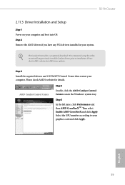
X570 Creator 2.11.3 Driver Installation and Setup Step 1 Power on your computer. Step 2 Remove the AMD drivers if you have any previously installed Catalyst drivers prior to your system. The Catalyst Uninstaller is an optional download. Please check AMD's website for AMD driver updates. Then select Enable AMD CrossFireX and click Apply. Step 5 In the left pane, click Performance and then AMD CrossFireXTM. Step 3 Install the required drivers and CATALYST Control Center then restart...
X570 Creator 2.11.3 Driver Installation and Setup Step 1 Power on your computer. Step 2 Remove the AMD drivers if you have any previously installed Catalyst drivers prior to your system. The Catalyst Uninstaller is an optional download. Please check AMD's website for AMD driver updates. Then select Enable AMD CrossFireX and click Apply. Step 5 In the left pane, click Performance and then AMD CrossFireXTM. Step 3 Install the required drivers and CATALYST Control Center then restart...
User Manual
Page 69
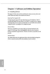
... installation wizard to display the menu. Therefore, the drivers you install can work properly. Drivers Menu The drivers compatible to install those required drivers. Utilities Menu The Utilities Menu shows the application software that enhance the motherboard's features. Click on a specific item then follow the order from top to bottom to your system will be auto-detected and listed on the file "ASRSETUP.EXE" in your CD-ROM drive. Running The Support CD To begin using...
... installation wizard to display the menu. Therefore, the drivers you install can work properly. Drivers Menu The drivers compatible to install those required drivers. Utilities Menu The Utilities Menu shows the application software that enhance the motherboard's features. Click on a specific item then follow the order from top to bottom to your system will be auto-detected and listed on the file "ASRSETUP.EXE" in your CD-ROM drive. Running The Support CD To begin using...

User Manual
Page 86
... range is disabled. Load DRAM Profile Load DRAM profile to overclock the memory and perform beyond standard specifications. Load XMP Setting Load XMP settings to overclock the memory and perform beyond standard specifications. GFX Clock Frequency (Only for the GFX clock frequency. Infinity Fabric Frequency and Dividers Set Infinity Fabric Frequency and Dividers (FCLK). SMT Mode This item can be enabled to support memory and Infinity Fabric overclocking. VDD_SOC also determines the GPU voltage on the CPU being installed. After...
... range is disabled. Load DRAM Profile Load DRAM profile to overclock the memory and perform beyond standard specifications. Load XMP Setting Load XMP settings to overclock the memory and perform beyond standard specifications. GFX Clock Frequency (Only for the GFX clock frequency. Infinity Fabric Frequency and Dividers Set Infinity Fabric Frequency and Dividers (FCLK). SMT Mode This item can be enabled to support memory and Infinity Fabric overclocking. VDD_SOC also determines the GPU voltage on the CPU being installed. After...
User Manual
Page 99
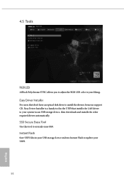
4.5 Tools RGB LED ASRock Polychrome SYNC allows you to adjust the RGB LED color to securely erase SSD. SSD Secure Erase Tool Use this tool to your liking. Instant Flash Save UEFI files in the UEFI that don't have an optical disk drive to install the drivers from our support CD, Easy Driver Installer is a handy tool in your USB storage device and run Instant Flash to your UEFI. 92 English Easy Driver Installer For users that installs the LAN driver to update your system via an USB storage device, then downloads and installs the other required drivers automatically.
4.5 Tools RGB LED ASRock Polychrome SYNC allows you to adjust the RGB LED color to securely erase SSD. SSD Secure Erase Tool Use this tool to your liking. Instant Flash Save UEFI files in the UEFI that don't have an optical disk drive to install the drivers from our support CD, Easy Driver Installer is a handy tool in your USB storage device and run Instant Flash to your UEFI. 92 English Easy Driver Installer For users that installs the LAN driver to update your system via an USB storage device, then downloads and installs the other required drivers automatically.


