
RAID Installation Guide
Page 2
... any HDDs of data from one logical unit. RAID 0 (Data Striping) RAID 0 is an instruction for "Redundant Array of the data in parallel, interleaved stacks. Although RAID 0 function can start to use the onboard RAID Option ROM Utility to configure RAID. 1.1 Introduction to RAID The term "RAID" stands for you make a SATA driver diskette, press or to enter BIOS setup to a second drive. It will improve data access and storage since the disk array management software...
... any HDDs of data from one logical unit. RAID 0 (Data Striping) RAID 0 is an instruction for "Redundant Array of the data in parallel, interleaved stacks. Although RAID 0 function can start to use the onboard RAID Option ROM Utility to configure RAID. 1.1 Introduction to RAID The term "RAID" stands for you make a SATA driver diskette, press or to enter BIOS setup to a second drive. It will improve data access and storage since the disk array management software...

RAID Installation Guide
Page 8
During system boot, press or key to find the driver inside your USB flash disk. C. E. Click to enter UEFI setup utility. B. Please download the "SATA Floppy Imaged driver" from ASRock's website A. STEP 3.1: Copy RAID driver to a USB flash drive You can choose either STEP 3.1 or STEP 3.2 to Tools Easy RAID Installer F. Plug a USB drive into the DVD-ROM drive. B. STEP 3.2: Download driver from ASRock's website and unzip the file into your USB flash drive. 8 During Windows installation process, when Disk selection page show up, please click . Go to...
During system boot, press or key to find the driver inside your USB flash disk. C. E. Click to enter UEFI setup utility. B. Please download the "SATA Floppy Imaged driver" from ASRock's website A. STEP 3.1: Copy RAID driver to a USB flash drive You can choose either STEP 3.1 or STEP 3.2 to Tools Easy RAID Installer F. Plug a USB drive into the DVD-ROM drive. B. STEP 3.2: Download driver from ASRock's website and unzip the file into your USB flash drive. 8 During Windows installation process, when Disk selection page show up, please click . Go to...

RAID Installation Guide
Page 12
... DisksCheck AllApply ChangesCreate Array. *Be sure to exit. Plug a USB drive into your USB flash disk. 12 A. Please install the DVD-ROM. During system boot, press or key to finish the driver copy process. D. Insert the Support CD into the DVD-ROM drive. STEP 2.2: Download driver from ASRock's website and unzip the file into one of the USB port. C. Follow instructions to enter UEFI setup utility. E. G. Go to finish the configuration. STEP 2.1: Copy RAID driver to a USB flash drive...
... DisksCheck AllApply ChangesCreate Array. *Be sure to exit. Plug a USB drive into your USB flash disk. 12 A. Please install the DVD-ROM. During system boot, press or key to finish the driver copy process. D. Insert the Support CD into the DVD-ROM drive. STEP 2.2: Download driver from ASRock's website and unzip the file into one of the USB port. C. Follow instructions to enter UEFI setup utility. E. G. Go to finish the configuration. STEP 2.1: Copy RAID driver to a USB flash drive...

Quick Installation Guide
Page 4
... Fan Connector (CPU_FAN2/WP) 8 2 x 288-pin DDR4 DIMM Slots (DDR4_A2, DDR4_B2) 9 RGB LED Header (RGB_LED2) 10 ATX Power Connector (ATXPWR1) 11 USB 3.1 Gen1 Header (USB3_11_12) 12 AMD LED Fan USB Header (USB_5) 13 SATA3 Connectors (SATA3_1_2) 14 SATA3 Connectors (SATA3_3_4) 15 SATA3 Connectors (SATA3_5_6) 16 SATA3 Connectors (SATA3_7_8) 17 Power Button (PWRBTN1) 18 Power LED and Speaker Header (SPK_PLED1) 19 System Panel Header (PANEL1) 20 Chassis/Water Pump Fan Connector (CHA_FAN1/WP) 21 USB 3.1 Gen1 Header (USB3_9_10) 22 Reset Button (RSTBTN1) 23 Clear CMOS Button (CLRCBTN1) 24 USB 2.0 Header...
... Fan Connector (CPU_FAN2/WP) 8 2 x 288-pin DDR4 DIMM Slots (DDR4_A2, DDR4_B2) 9 RGB LED Header (RGB_LED2) 10 ATX Power Connector (ATXPWR1) 11 USB 3.1 Gen1 Header (USB3_11_12) 12 AMD LED Fan USB Header (USB_5) 13 SATA3 Connectors (SATA3_1_2) 14 SATA3 Connectors (SATA3_3_4) 15 SATA3 Connectors (SATA3_5_6) 16 SATA3 Connectors (SATA3_7_8) 17 Power Button (PWRBTN1) 18 Power LED and Speaker Header (SPK_PLED1) 19 System Panel Header (PANEL1) 20 Chassis/Water Pump Fan Connector (CHA_FAN1/WP) 21 USB 3.1 Gen1 Header (USB3_9_10) 22 Reset Button (RSTBTN1) 23 Clear CMOS Button (CLRCBTN1) 24 USB 2.0 Header...
Quick Installation Guide
Page 7
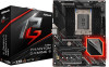
... • ASRock X399 Phantom Gaming 6 Quick Installation Guide • ASRock X399 Phantom Gaming 6 Support CD • 1 x I/O Panel Shield • 4 x Serial ATA (SATA) Data Cables (Optional) • 1 x ASRock SLI_HB_Bridge_2S Card (Optional) • 4 x Screws for purchasing ASRock X399 Phantom Gaming 6 motherboard, a reliable motherboard produced under ASRock's consistently stringent quality control. X399 Phantom Gaming 6 Chapter 1 Introduction Thank you are using. In case any modifications of this motherboard, please visit our website for specific information about the model you...
... • ASRock X399 Phantom Gaming 6 Quick Installation Guide • ASRock X399 Phantom Gaming 6 Support CD • 1 x I/O Panel Shield • 4 x Serial ATA (SATA) Data Cables (Optional) • 1 x ASRock SLI_HB_Bridge_2S Card (Optional) • 4 x Screws for purchasing ASRock X399 Phantom Gaming 6 motherboard, a reliable motherboard produced under ASRock's consistently stringent quality control. X399 Phantom Gaming 6 Chapter 1 Introduction Thank you are using. In case any modifications of this motherboard, please visit our website for specific information about the model you...
Quick Installation Guide
Page 9
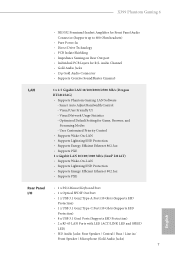
... Type-C Port (10 Gb/s) (Supports ESD Protection) • 8 x USB 3.1 Gen1 Ports (Supports ESD Protection) • 2 x RJ-45 LAN Ports with LED (ACT/LINK LED and SPEED LED) • HD Audio Jacks: Rear Speaker / Central / Bass / Line in / Front Speaker / Microphone (Gold Audio Jacks) 7 English Smart Auto Adjust Bandwidth Control - Visual User Friendly UI - X399 Phantom Gaming 6 • NE5532 Premium Headset Amplifier for Front Panel Audio Connector (Supports up to 600 Ohm headsets) • Pure Power-In • Direct Drive Technology...
... Type-C Port (10 Gb/s) (Supports ESD Protection) • 8 x USB 3.1 Gen1 Ports (Supports ESD Protection) • 2 x RJ-45 LAN Ports with LED (ACT/LINK LED and SPEED LED) • HD Audio Jacks: Rear Speaker / Central / Bass / Line in / Front Speaker / Microphone (Gold Audio Jacks) 7 English Smart Auto Adjust Bandwidth Control - Visual User Friendly UI - X399 Phantom Gaming 6 • NE5532 Premium Headset Amplifier for Front Panel Audio Connector (Supports up to 600 Ohm headsets) • Pure Power-In • Direct Drive Technology...

Quick Installation Guide
Page 10
... and M.2 PCI Express module up to Gen3 x4 (32 Gb/s)** * Supports NVMe SSD as boot disks * Supports ASRock U.2 Kit Connector • 1 x TPM Header • 1 x Power LED and Speaker Header • 2 x RGB LED Headers * Support in total up to 12V/3A, 36W LED Strip • 1 x Addressable LED Header * Supports in total up to 5V/3A, 15W LED Strip • 1 x CPU Fan Connector (4-pin) * The CPU Fan Connector supports the CPU fan of maximum 1A (12W) fan power. • 1 x CPU/Water Pump Fan Connector (4-pin) (Smart Fan Speed Control) * The CPU/Water Pump Fan supports the...
... and M.2 PCI Express module up to Gen3 x4 (32 Gb/s)** * Supports NVMe SSD as boot disks * Supports ASRock U.2 Kit Connector • 1 x TPM Header • 1 x Power LED and Speaker Header • 2 x RGB LED Headers * Support in total up to 12V/3A, 36W LED Strip • 1 x Addressable LED Header * Supports in total up to 5V/3A, 15W LED Strip • 1 x CPU Fan Connector (4-pin) * The CPU Fan Connector supports the CPU fan of maximum 1A (12W) fan power. • 1 x CPU/Water Pump Fan Connector (4-pin) (Smart Fan Speed Control) * The CPU/Water Pump Fan supports the...
Quick Installation Guide
Page 11
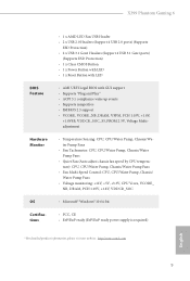
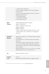
X399 Phantom Gaming 6 BIOS Feature Hardware Monitor OS Certifications • 1 x AMD LED Fan USB Header • 2 x USB 2.0 Headers (Support 4 USB 2.0 ports) (Supports ESD Protection) • 2 x USB 3.1 Gen1 Headers (Support 4 USB 3.1 Gen1 ports) (Supports ESD Protection) • 1 x Clear CMOS Button • 1 x Power Button with LED • 1 x Reset Button with LED • AMI UEFI Legal BIOS with GUI support • Supports "Plug and Play" • ACPI 5.1 compliance wake up events • Supports jumperfree • SMBIOS 2.3 support • VCORE, VCORE_NB, DRAM, VPPM, PCH 1.05V, ...
X399 Phantom Gaming 6 BIOS Feature Hardware Monitor OS Certifications • 1 x AMD LED Fan USB Header • 2 x USB 2.0 Headers (Support 4 USB 2.0 ports) (Supports ESD Protection) • 2 x USB 3.1 Gen1 Headers (Support 4 USB 3.1 Gen1 ports) (Supports ESD Protection) • 1 x Clear CMOS Button • 1 x Power Button with LED • 1 x Reset Button with LED • AMI UEFI Legal BIOS with GUI support • Supports "Plug and Play" • ACPI 5.1 compliance wake up events • Supports jumperfree • SMBIOS 2.3 support • VCORE, VCORE_NB, DRAM, VPPM, PCH 1.05V, ...

Quick Installation Guide
Page 28
... a 4-Pin CPU fan (Quiet Fan) connector. CPU Fan Connector (4-pin CPU_FAN1) (see p.1, No. 32) GND FAN_VOLTAGE FAN_SPEED FAN_SPEED_CONTROL 1 2 34 This motherboard provides three 4-Pin water cooling chassis fan connectors. Please follow the instructions in the Realtek Control panel and adjust "Recording Volume". MIC_RET and OUT_RET are for connecting audio devices to the front audio panel. * Connect the audio device to install your system. 2. If you use an AC'97 audio panel, please install it to connect them for the AC'97 audio panel. Connect...
... a 4-Pin CPU fan (Quiet Fan) connector. CPU Fan Connector (4-pin CPU_FAN1) (see p.1, No. 32) GND FAN_VOLTAGE FAN_SPEED FAN_SPEED_CONTROL 1 2 34 This motherboard provides three 4-Pin water cooling chassis fan connectors. Please follow the instructions in the Realtek Control panel and adjust "Recording Volume". MIC_RET and OUT_RET are for connecting audio devices to the front audio panel. * Connect the audio device to install your system. 2. If you use an AC'97 audio panel, please install it to connect them for the AC'97 audio panel. Connect...
User Manual
Page 7
... latest VGA cards and CPU support list on ASRock's website without notice. Chapter 4 contains the configuration guide of the software and utilities. Chapter 3 contains the operation guide of the BIOS setup. ASRock website http://www.asrock.com. 1.1 Package Contents • ASRock X399 Phantom Gaming 6 Motherboard (ATX Form Factor) • ASRock X399 Phantom Gaming 6 Quick Installation Guide • ASRock X399 Phantom Gaming 6 Support CD • 1 x I/O Panel Shield • 4 x Serial ATA (SATA) Data Cables (Optional) • 1 x ASRock SLI_HB_Bridge_2S Card (Optional) •...
... latest VGA cards and CPU support list on ASRock's website without notice. Chapter 4 contains the configuration guide of the software and utilities. Chapter 3 contains the operation guide of the BIOS setup. ASRock website http://www.asrock.com. 1.1 Package Contents • ASRock X399 Phantom Gaming 6 Motherboard (ATX Form Factor) • ASRock X399 Phantom Gaming 6 Quick Installation Guide • ASRock X399 Phantom Gaming 6 Support CD • 1 x I/O Panel Shield • 4 x Serial ATA (SATA) Data Cables (Optional) • 1 x ASRock SLI_HB_Bridge_2S Card (Optional) •...

User Manual
Page 10
... and M.2 PCI Express module up to Gen3 x4 (32 Gb/s)** * Supports NVMe SSD as boot disks * Supports ASRock U.2 Kit Connector • 1 x TPM Header • 1 x Power LED and Speaker Header • 2 x RGB LED Headers * Support in total up to 12V/3A, 36W LED Strip • 1 x Addressable LED Header * Supports in total up to 5V/3A, 15W LED Strip • 1 x CPU Fan Connector (4-pin) * The CPU Fan Connector supports the CPU fan of maximum 1A (12W) fan power. • 1 x CPU/Water Pump Fan Connector (4-pin) (Smart Fan Speed Control) * The CPU/Water Pump Fan supports the...
... and M.2 PCI Express module up to Gen3 x4 (32 Gb/s)** * Supports NVMe SSD as boot disks * Supports ASRock U.2 Kit Connector • 1 x TPM Header • 1 x Power LED and Speaker Header • 2 x RGB LED Headers * Support in total up to 12V/3A, 36W LED Strip • 1 x Addressable LED Header * Supports in total up to 5V/3A, 15W LED Strip • 1 x CPU Fan Connector (4-pin) * The CPU Fan Connector supports the CPU fan of maximum 1A (12W) fan power. • 1 x CPU/Water Pump Fan Connector (4-pin) (Smart Fan Speed Control) * The CPU/Water Pump Fan supports the...
User Manual
Page 11
X399 Phantom Gaming 6 BIOS Feature Hardware Monitor OS Certifications • 1 x AMD LED Fan USB Header • 2 x USB 2.0 Headers (Support 4 USB 2.0 ports) (Supports ESD Protection) • 2 x USB 3.1 Gen1 Headers (Support 4 USB 3.1 Gen1 ports) (Supports ESD Protection) • 1 x Clear CMOS Button • 1 x Power Button with LED • 1 x Reset Button with LED • AMI UEFI Legal BIOS with GUI support • Supports "Plug and Play" • ACPI 5.1 compliance wake up events • Supports jumperfree • SMBIOS 2.3 support • VCORE, VCORE_NB, DRAM, VPPM, PCH 1.05V, ...
X399 Phantom Gaming 6 BIOS Feature Hardware Monitor OS Certifications • 1 x AMD LED Fan USB Header • 2 x USB 2.0 Headers (Support 4 USB 2.0 ports) (Supports ESD Protection) • 2 x USB 3.1 Gen1 Headers (Support 4 USB 3.1 Gen1 ports) (Supports ESD Protection) • 1 x Clear CMOS Button • 1 x Power Button with LED • 1 x Reset Button with LED • AMI UEFI Legal BIOS with GUI support • Supports "Plug and Play" • ACPI 5.1 compliance wake up events • Supports jumperfree • SMBIOS 2.3 support • VCORE, VCORE_NB, DRAM, VPPM, PCH 1.05V, ...

User Manual
Page 14
... Fan Connector (CPU_FAN2/WP) 8 2 x 288-pin DDR4 DIMM Slots (DDR4_A2, DDR4_B2) 9 RGB LED Header (RGB_LED2) 10 ATX Power Connector (ATXPWR1) 11 USB 3.1 Gen1 Header (USB3_11_12) 12 AMD LED Fan USB Header (USB_5) 13 SATA3 Connectors (SATA3_1_2) 14 SATA3 Connectors (SATA3_3_4) 15 SATA3 Connectors (SATA3_5_6) 16 SATA3 Connectors (SATA3_7_8) 17 Power Button (PWRBTN1) 18 Power LED and Speaker Header (SPK_PLED1) 19 System Panel Header (PANEL1) 20 Chassis/Water Pump Fan Connector (CHA_FAN1/WP) 21 USB 3.1 Gen1 Header (USB3_9_10) 22 Reset Button (RSTBTN1) 23 Clear CMOS Button (CLRCBTN1) 24 USB 2.0 Header...
... Fan Connector (CPU_FAN2/WP) 8 2 x 288-pin DDR4 DIMM Slots (DDR4_A2, DDR4_B2) 9 RGB LED Header (RGB_LED2) 10 ATX Power Connector (ATXPWR1) 11 USB 3.1 Gen1 Header (USB3_11_12) 12 AMD LED Fan USB Header (USB_5) 13 SATA3 Connectors (SATA3_1_2) 14 SATA3 Connectors (SATA3_3_4) 15 SATA3 Connectors (SATA3_5_6) 16 SATA3 Connectors (SATA3_7_8) 17 Power Button (PWRBTN1) 18 Power LED and Speaker Header (SPK_PLED1) 19 System Panel Header (PANEL1) 20 Chassis/Water Pump Fan Connector (CHA_FAN1/WP) 21 USB 3.1 Gen1 Header (USB3_9_10) 22 Reset Button (RSTBTN1) 23 Clear CMOS Button (CLRCBTN1) 24 USB 2.0 Header...

User Manual
Page 32
... the front mic, go to install your system. 2. CPU Fan Connector (4-pin CPU_FAN1) (see p.7, No. 32) GND FAN_VOLTAGE FAN_SPEED FAN_SPEED_CONTROL This motherboard provides three 4-Pin water cooling chassis fan 1 2 34 connectors. Please follow the instructions in our manual and chassis manual to the "FrontMic" Tab in the Realtek Control panel and adjust "Recording Volume". C. Connect Ground (GND) to connect them for the AC'97 audio panel. You don't need to...
... the front mic, go to install your system. 2. CPU Fan Connector (4-pin CPU_FAN1) (see p.7, No. 32) GND FAN_VOLTAGE FAN_SPEED FAN_SPEED_CONTROL This motherboard provides three 4-Pin water cooling chassis fan 1 2 34 connectors. Please follow the instructions in our manual and chassis manual to the "FrontMic" Tab in the Realtek Control panel and adjust "Recording Volume". C. Connect Ground (GND) to connect them for the AC'97 audio panel. You don't need to...

User Manual
Page 41
... PCI Express x16 graphics cards. 1. Please refer to your graphics card vendor for detailed installation guide. 2.9.1 Installing Two CrossFireXTM-Ready Graphics Cards Step 1 Insert one graphics card into PCIE1 slot and the other graphics card to the AMD's website for details. 4. X399 Phantom Gaming 6 2.9 CrossFireXTM, 3-Way CrossFireXTM and Quad CrossFireXTM Operation Guide This motherboard supports CrossFireXTM, 3-way CrossFireXTMand Quad CrossFireXTM that allows you pair a 12-pipe CrossFireXTM Edition card with this motherboard. You should only use a AMD...
... PCI Express x16 graphics cards. 1. Please refer to your graphics card vendor for detailed installation guide. 2.9.1 Installing Two CrossFireXTM-Ready Graphics Cards Step 1 Insert one graphics card into PCIE1 slot and the other graphics card to the AMD's website for details. 4. X399 Phantom Gaming 6 2.9 CrossFireXTM, 3-Way CrossFireXTM and Quad CrossFireXTM Operation Guide This motherboard supports CrossFireXTM, 3-way CrossFireXTMand Quad CrossFireXTM that allows you pair a 12-pipe CrossFireXTM Edition card with this motherboard. You should only use a AMD...
User Manual
Page 43
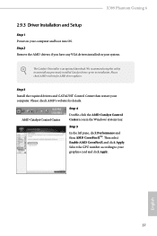
... X399 Phantom Gaming 6 2.9.3 Driver Installation and Setup Step 1 Power on your graphics card and click Apply. Step 5 In the left pane, click Performance and then AMD CrossFireXTM. Select the GPU number according to installation. The Catalyst Uninstaller is an optional download. Please check AMD's website for details. AMD Catalyst Control Center Step 4 Double-click the AMD Catalyst Control Center icon in your computer. Please check AMD's website for AMD driver updates. Step 3 Install...
... X399 Phantom Gaming 6 2.9.3 Driver Installation and Setup Step 1 Power on your graphics card and click Apply. Step 5 In the left pane, click Performance and then AMD CrossFireXTM. Select the GPU number according to installation. The Catalyst Uninstaller is an optional download. Please check AMD's website for details. AMD Catalyst Control Center Step 4 Double-click the AMD Catalyst Control Center icon in your computer. Please check AMD's website for AMD driver updates. Step 3 Install...
User Manual
Page 57
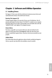
... the motherboard's features. X399 Phantom Gaming 6 Chapter 3 Software and Utilities Operation 3.1 Installing Drivers The Support CD that comes with the motherboard contains necessary drivers and useful utilities that the motherboard supports. The CD automatically displays the Main Menu if "AUTORUN" is enabled in the Support CD to display the menu. Drivers Menu The drivers compatible to your CD-ROM drive. Running The Support CD To begin using the support CD, insert the CD into your system will be auto-detected and listed on a specific...
... the motherboard's features. X399 Phantom Gaming 6 Chapter 3 Software and Utilities Operation 3.1 Installing Drivers The Support CD that comes with the motherboard contains necessary drivers and useful utilities that the motherboard supports. The CD automatically displays the Main Menu if "AUTORUN" is enabled in the Support CD to display the menu. Drivers Menu The drivers compatible to your CD-ROM drive. Running The Support CD To begin using the support CD, insert the CD into your system will be auto-detected and listed on a specific...

User Manual
Page 82
Serial Port Address Select the address of the Serial port. PS2 Y-Cable Enable the PS2 Y-Cable or set this option to Auto. 76 English 4.4.5 Super IO Configuration Serial Port Enable or disable the Serial port.
Serial Port Address Select the address of the Serial port. PS2 Y-Cable Enable the PS2 Y-Cable or set this option to Auto. 76 English 4.4.5 Super IO Configuration Serial Port Enable or disable the Serial port.

User Manual
Page 86
... C1 state to automatically configures this setting. SEV-ES ASID Space Limit SEV VMs using ASIDs below the SEV-ES ASID Space Limit must enable the SEV-ES feature. Power Supply Idle Control Enables or disables Package C6 State. Streaming Stores Control Enables or disables the streaming stores functionality. DF Common Options DRAM scrub time Provide a value that is disabled, specific uncorrected errors detected by the PSP...
... C1 state to automatically configures this setting. SEV-ES ASID Space Limit SEV VMs using ASIDs below the SEV-ES ASID Space Limit must enable the SEV-ES feature. Power Supply Idle Control Enables or disables Package C6 State. Streaming Stores Control Enables or disables the streaming stores functionality. DF Common Options DRAM scrub time Provide a value that is disabled, specific uncorrected errors detected by the PSP...

User Manual
Page 87
... size is enabled. This determines the starting address of DRAM or distributed. Note that it will always be at the top of the interleave (bit 8, 9, 10 or 11). X399 Phantom Gaming 6 Disable DF sync flood propagation Control DF::PIEConfig[DisSyncFloodProp]. Note that channel, die, and socket has requirements on error Controls DF::PIEConfig[DisImmSyncFloodOnFatalError] Disabling this option's setting. This field should not be ignored if the memory doesn't support...
... size is enabled. This determines the starting address of DRAM or distributed. Note that it will always be at the top of the interleave (bit 8, 9, 10 or 11). X399 Phantom Gaming 6 Disable DF sync flood propagation Control DF::PIEConfig[DisSyncFloodProp]. Note that channel, die, and socket has requirements on error Controls DF::PIEConfig[DisImmSyncFloodOnFatalError] Disabling this option's setting. This field should not be ignored if the memory doesn't support...


