
User Manual
Page 5
... 51 3.4 ASRock RGB LED 52 Chapter 4 UEFI SETUP UTILITY 54 4.1 Introduction 54 4.2 EZ Mode 55 4.3 Advanced Mode 56 4.3.1 UEFI Menu Bar 56 4.3.2 Navigation Keys 57 4.4 Main Screen 58 4.5 OC Tweaker Screen 59 4.6 Advanced Screen 72 4.6.1 CPU Configuration 73 4.6.2 IIO Configuration 75 4.6.3 Chipset Configuration 76 4.6.4 Storage Configuration 78 4.6.5 Intel® Thunderbolt™ 79
... 51 3.4 ASRock RGB LED 52 Chapter 4 UEFI SETUP UTILITY 54 4.1 Introduction 54 4.2 EZ Mode 55 4.3 Advanced Mode 56 4.3.1 UEFI Menu Bar 56 4.3.2 Navigation Keys 57 4.4 Main Screen 58 4.5 OC Tweaker Screen 59 4.6 Advanced Screen 72 4.6.1 CPU Configuration 73 4.6.2 IIO Configuration 75 4.6.3 Chipset Configuration 76 4.6.4 Storage Configuration 78 4.6.5 Intel® Thunderbolt™ 79

User Manual
Page 11
tor) • 1 x Front Panel Audio Connector (15μ Gold Audio Connec- X299 Extreme4 * CPU_OPT/W_PUMP1, CHA_FAN1, CHA_FAN2 and CHA_ FAN3/W_PUMP2 can auto detect if 3-pin or 4-pin fan is required) 5 English nector) • 2 x 8 pin 12V Power Connectors (Hi-Density Power Connec- tor) • 1 x Thunderbolt AIC Connector (5-pin) • 2 x USB 2.0 Headers (Support 4 USB 2.0 ports...
tor) • 1 x Front Panel Audio Connector (15μ Gold Audio Connec- X299 Extreme4 * CPU_OPT/W_PUMP1, CHA_FAN1, CHA_FAN2 and CHA_ FAN3/W_PUMP2 can auto detect if 3-pin or 4-pin fan is required) 5 English nector) • 2 x 8 pin 12V Power Connectors (Hi-Density Power Connec- tor) • 1 x Thunderbolt AIC Connector (5-pin) • 2 x USB 2.0 Headers (Support 4 USB 2.0 ports...

User Manual
Page 14
... (CHA_FAN1) 21 Performance Mode / Easy OC Header (PM_EO) 22 USB 2.0 Header (USB_5_6) 23 USB 2.0 Header (USB_3_4) 24 Chassis Fan / Waterpump Fan Connector (CHA_FAN3/W_PUMP2) 25 Thunderbolt AIC Header (TB1) 26 Clear CMOS Jumper (CLRMOS1) 27 RGB LED Header (RGB_LED1) 28 TPM Header (TPMS1) 29 Front Panel Audio Header (HD_AUDIO1) 8 English No.
... (CHA_FAN1) 21 Performance Mode / Easy OC Header (PM_EO) 22 USB 2.0 Header (USB_5_6) 23 USB 2.0 Header (USB_3_4) 24 Chassis Fan / Waterpump Fan Connector (CHA_FAN3/W_PUMP2) 25 Thunderbolt AIC Header (TB1) 26 Clear CMOS Jumper (CLRMOS1) 27 RGB LED Header (RGB_LED1) 28 TPM Header (TPMS1) 29 Front Panel Audio Header (HD_AUDIO1) 8 English No.
User Manual
Page 31
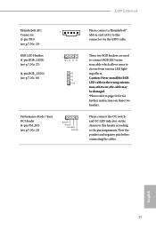
X299 Extreme4 Thunderbolt AIC Connector (5-pin TB1) (see p.7, No. 25) RGB LED Headers (4-pin RGB_LED1) (see p.7, No. 27) (4-pin RGB_LED2) (see p.7, No. 10) 1 1 12V G R B Performance Mode / Easy OC ... instructions on the chassis to this connector via the GPIO cable. Note the positive and negative pins before connecting the cables. English 25 Please connect a Thunderbolt™ add-in the wrong orientation; otherwise, the cable may be damaged. *Please refer to this header according to choose from various LED lighting effects...
X299 Extreme4 Thunderbolt AIC Connector (5-pin TB1) (see p.7, No. 25) RGB LED Headers (4-pin RGB_LED1) (see p.7, No. 27) (4-pin RGB_LED2) (see p.7, No. 10) 1 1 12V G R B Performance Mode / Easy OC ... instructions on the chassis to this connector via the GPIO cable. Note the positive and negative pins before connecting the cables. English 25 Please connect a Thunderbolt™ add-in the wrong orientation; otherwise, the cable may be damaged. *Please refer to this header according to choose from various LED lighting effects...

User Manual
Page 85
4.6.5 Intel® Thunderbolt™ X299 Extreme4 Intel(R) Thunderbolt Technology Enable/Disable the Intel(R) Thunderbolt function. Security Level Allows you to choose a security level for the Thunderbolt ports. 79 English
4.6.5 Intel® Thunderbolt™ X299 Extreme4 Intel(R) Thunderbolt Technology Enable/Disable the Intel(R) Thunderbolt function. Security Level Allows you to choose a security level for the Thunderbolt ports. 79 English

Quick Installation Guide
Page 4
... (CHA_FAN1) 21 Performance Mode / Easy OC Header (PM_EO) 22 USB 2.0 Header (USB_5_6) 23 USB 2.0 Header (USB_3_4) 24 Chassis Fan / Waterpump Fan Connector (CHA_FAN3/W_PUMP2) 25 Thunderbolt AIC Header (TB1) 26 Clear CMOS Jumper (CLRMOS1) 27 RGB LED Header (RGB_LED1) 28 TPM Header (TPMS1) 29 Front Panel Audio Header (HD_AUDIO1) 2 English
... (CHA_FAN1) 21 Performance Mode / Easy OC Header (PM_EO) 22 USB 2.0 Header (USB_5_6) 23 USB 2.0 Header (USB_3_4) 24 Chassis Fan / Waterpump Fan Connector (CHA_FAN3/W_PUMP2) 25 Thunderbolt AIC Header (TB1) 26 Clear CMOS Jumper (CLRMOS1) 27 RGB LED Header (RGB_LED1) 28 TPM Header (TPMS1) 29 Front Panel Audio Header (HD_AUDIO1) 2 English

Quick Installation Guide
Page 11
X299 Extreme4 BIOS Feature Hardware Monitor OS Certifications * CPU_OPT/W_PUMP1, CHA_FAN1, CHA_FAN2 and CHA_ FAN3/W_PUMP2 can auto detect if 3-pin or 4-pin fan is required) 9 English tor) • 1 x Front Panel Audio Connector (15μ Gold Audio Connec- tor) • 1 x Thunderbolt AIC Connector (5-pin) • 2 x USB 2.0 Headers (Support 4 USB 2.0 ports) (Supports ESD Protection) •...
X299 Extreme4 BIOS Feature Hardware Monitor OS Certifications * CPU_OPT/W_PUMP1, CHA_FAN1, CHA_FAN2 and CHA_ FAN3/W_PUMP2 can auto detect if 3-pin or 4-pin fan is required) 9 English tor) • 1 x Front Panel Audio Connector (15μ Gold Audio Connec- tor) • 1 x Thunderbolt AIC Connector (5-pin) • 2 x USB 2.0 Headers (Support 4 USB 2.0 ports) (Supports ESD Protection) •...
Quick Installation Guide
Page 27
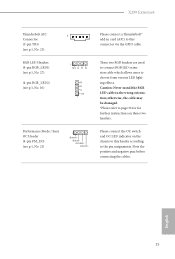
Please connect the OC switch and OC LED indicator on these two headers. Please connect a Thunderbolt™ add-in the wrong orientation; Caution: Never install the RGB LED cable in card (AIC) to the pin assignments. otherwise, the cable may be... cable which allows users to page 36 for for further instructions on the chassis to this header according to this connector via the GPIO cable. X299 Extreme4 Thunderbolt AIC Connector (5-pin TB1) (see p.1, No. 25) RGB LED Headers (4-pin RGB_LED1) (see p.1, No. 27) (4-pin RGB_LED2) (see p.1, No. 10) 1 1 12V G R B Performance Mode / Easy ...
Please connect the OC switch and OC LED indicator on these two headers. Please connect a Thunderbolt™ add-in the wrong orientation; Caution: Never install the RGB LED cable in card (AIC) to the pin assignments. otherwise, the cable may be... cable which allows users to page 36 for for further instructions on the chassis to this header according to this connector via the GPIO cable. X299 Extreme4 Thunderbolt AIC Connector (5-pin TB1) (see p.1, No. 25) RGB LED Headers (4-pin RGB_LED1) (see p.1, No. 27) (4-pin RGB_LED2) (see p.1, No. 10) 1 1 12V G R B Performance Mode / Easy ...

Quick Installation Guide
Page 156
...;CHA_FAN2 ͓Αͼ CHA_ FAN3/W_PUMP2 3 ϐϯ·ͨ 4 1 x 24 ϐϯ ATX λʔʣ • 2 x 8 ϐϯ 12V 1 x 15 1 x Thunderbolt AIC ίωΫλ (5 ϐϯ ) • 2 x USB 2.0 ϔομʔʢ4 ͭͷ USB 2.0 ์ిʢESD 1 x USB 3.1 Gen1 ϔο...
...;CHA_FAN2 ͓Αͼ CHA_ FAN3/W_PUMP2 3 ϐϯ·ͨ 4 1 x 24 ϐϯ ATX λʔʣ • 2 x 8 ϐϯ 12V 1 x 15 1 x Thunderbolt AIC ίωΫλ (5 ϐϯ ) • 2 x USB 2.0 ϔομʔʢ4 ͭͷ USB 2.0 ์ిʢESD 1 x USB 3.1 Gen1 ϔο...

Quick Installation Guide
Page 170
BIOS * CPU_OPT/W_PUMP1、CHA_FAN1、CHA_FAN2 和 CHA_FAN3/W_ PUMP2 3 针脚或 4 1 x 24 针 ATX 2 x 8 针 12V 1 x 15 1 x Thunderbolt AIC 接口 (5 针 ) • 2 x USB 2.0 4 个 USB 2.0 ESD 1 x USB 3.1 Gen1 2 个 USB 3.1 Gen1 端口, 支持 ESD 1 x • AMI UEFI Legal BIOS ...
BIOS * CPU_OPT/W_PUMP1、CHA_FAN1、CHA_FAN2 和 CHA_FAN3/W_ PUMP2 3 针脚或 4 1 x 24 针 ATX 2 x 8 针 12V 1 x 15 1 x Thunderbolt AIC 接口 (5 针 ) • 2 x USB 2.0 4 个 USB 2.0 ESD 1 x USB 3.1 Gen1 2 个 USB 3.1 Gen1 端口, 支持 ESD 1 x • AMI UEFI Legal BIOS ...