
Intel Rapid Storage Guide
Page 12
...a RAID volume (F6 install method) In order to install an operating system onto a RAID volume, the RAID option must be enabled in the system BIOS, a RAID volume must be created, and the F6 installation method must be used to load the Intel® Rapid Storage Technology driver during POST, press... of hard drives and press Space to select the drive. When finished press Enter. 12 Create a RAID Volume Use the following steps to enter the BIOS Setup program after the Power-On-Self-Test (POST) memory test begins. 2. Click F2 or Delete to create a RAID volume. 1. Unless you have ...
...a RAID volume (F6 install method) In order to install an operating system onto a RAID volume, the RAID option must be enabled in the system BIOS, a RAID volume must be created, and the F6 installation method must be used to load the Intel® Rapid Storage Technology driver during POST, press... of hard drives and press Space to select the drive. When finished press Enter. 12 Create a RAID Volume Use the following steps to enter the BIOS Setup program after the Power-On-Self-Test (POST) memory test begins. 2. Click F2 or Delete to create a RAID volume. 1. Unless you have ...

RAID Installation Guide
Page 1
... a RAID array 8 2.4.1 Configuring a RAID array Using UEFI Setup Utility....... 9 2.4.2 Configuring a PCIE SSD RAID Array Using UEFI Setup Utility 13 2.4.3 Configuring a RAID array Using Intel RAID BIOS....... 18 3. Guide to SATA Hard Disks Installation and RAID Configuration 1. Installing Windows® on a HDD larger than 2TB in RAID mode 22 4. Guide to SATA...
... a RAID array 8 2.4.1 Configuring a RAID array Using UEFI Setup Utility....... 9 2.4.2 Configuring a PCIE SSD RAID Array Using UEFI Setup Utility 13 2.4.3 Configuring a RAID array Using Intel RAID BIOS....... 18 3. Guide to SATA Hard Disks Installation and RAID Configuration 1. Installing Windows® on a HDD larger than 2TB in RAID mode 22 4. Guide to SATA...

RAID Installation Guide
Page 6
... attached to remapable PCIe slot or PCIe M.2 connector. * The PCIe Storage device must be AHCI-controller based. * System must be in RAID mode. * The system BIOS must be the base storage size. WARNING!! Intel Rapid Storage Technology for the RAID 1 set is recommended to "Clear Disk Data" or not. It is...
... attached to remapable PCIe slot or PCIe M.2 connector. * The PCIe Storage device must be AHCI-controller based. * System must be in RAID mode. * The system BIOS must be the base storage size. WARNING!! Intel Rapid Storage Technology for the RAID 1 set is recommended to "Clear Disk Data" or not. It is...

RAID Installation Guide
Page 7
...If you want to install Windows® 10 64-bit OS on your system. 7 STEP 2: Use ASRock Easy RAID Installer Easy RAID Installer can copy the RAID driver from a support CD to enter BIOS setup utility. Follow the onscreen instruction to save the configuration changes and exit setup. Plug in your...Press [Enter] to [RAID]. STEP 4: Install Windows® 10 64-bit OS on your SATA / SATA2 / SATA3 HDDs with just one simple click in the BIOS before setting your USB storage device with RAID functions, please follow the procedures below. Boot your USB flash drive into a USB port B.
...If you want to install Windows® 10 64-bit OS on your system. 7 STEP 2: Use ASRock Easy RAID Installer Easy RAID Installer can copy the RAID driver from a support CD to enter BIOS setup utility. Follow the onscreen instruction to save the configuration changes and exit setup. Plug in your...Press [Enter] to [RAID]. STEP 4: Install Windows® 10 64-bit OS on your SATA / SATA2 / SATA3 HDDs with just one simple click in the BIOS before setting your USB storage device with RAID functions, please follow the procedures below. Boot your USB flash drive into a USB port B.

RAID Installation Guide
Page 8
2.4 Configuring a RAID array You can configure a RAID array using either UEFI Setup Utility or Intel® RAID BIOS setup utility, depending on the HDD capacity and the OS you are installing. OS HDD Capacity Ultra Fast Boot Over 2.2 TB Not supported Windows...Not supported Option ROM Setting UEFI SETUP UTILITY\Boot\ CSM [Launch Storage n/a OpROM policy] = [UEFI only] Required RAID Utility UEFI Setup Utility Intel® RAID BIOS setup utility OS HDD Capacity Ultra Fast Boot Windows 10 / 8.1 / 8 Under 2.2 Over 2.2 TB TB Over 2.2 TB Enabled Enabled Disabled Under 2.2 TB Disabled...
2.4 Configuring a RAID array You can configure a RAID array using either UEFI Setup Utility or Intel® RAID BIOS setup utility, depending on the HDD capacity and the OS you are installing. OS HDD Capacity Ultra Fast Boot Over 2.2 TB Not supported Windows...Not supported Option ROM Setting UEFI SETUP UTILITY\Boot\ CSM [Launch Storage n/a OpROM policy] = [UEFI only] Required RAID Utility UEFI Setup Utility Intel® RAID BIOS setup utility OS HDD Capacity Ultra Fast Boot Windows 10 / 8.1 / 8 Under 2.2 Over 2.2 TB TB Over 2.2 TB Enabled Enabled Disabled Under 2.2 TB Disabled...

RAID Installation Guide
Page 18
Create RAID Volume window appears. Press . Wait until you see the RAID software prompting you to press . In the Create Volume Menu, under Name item, please key-in a unique name with 1-16 letters for your computer. 2.4.3 Configuring a RAID array Using Intel RAID BIOS Reboot your RAID volume then press . Volume0 18 Then, the Intel RAID Utility -
Create RAID Volume window appears. Press . Wait until you see the RAID software prompting you to press . In the Create Volume Menu, under Name item, please key-in a unique name with 1-16 letters for your computer. 2.4.3 Configuring a RAID array Using Intel RAID BIOS Reboot your RAID volume then press . Volume0 18 Then, the Intel RAID Utility -

RAID Installation Guide
Page 21
After the completion, you will see the detailed information about the RAID that you are only allowed to create one RAID partition at a time under Windows environment to configure RAID functions after you want to delete a RAID volume, please select the option Delete RAID Volume, press , and then follow the instructions on the screen. 21 If you install OS. If you set up. Please note that you want to complete the setup of RAID. Press to create an extra RAID partition, please use the RAID utility under BIOS RAID environment.
After the completion, you will see the detailed information about the RAID that you are only allowed to create one RAID partition at a time under Windows environment to configure RAID functions after you want to delete a RAID volume, please select the option Delete RAID Volume, press , and then follow the instructions on the screen. 21 If you install OS. If you set up. Please note that you want to complete the setup of RAID. Press to create an extra RAID partition, please use the RAID utility under BIOS RAID environment.

RAID Installation Guide
Page 22
3. Installing Windows® on a HDD under 2TB in RAID mode After the UEFI and RAID BIOS setup you may start installing Windows® 10 64-bit OS as usual. 22
3. Installing Windows® on a HDD under 2TB in RAID mode After the UEFI and RAID BIOS setup you may start installing Windows® 10 64-bit OS as usual. 22

RAID Installation Guide
Page 23
After the UEFI and RAID BIOS setup, please follow the steps below. Please make sure to boot. 23 STEP 1: Copy Intel® RAID drivers into a USB flash disk You can download the drivers from ASRock's website and unzip the files into a USB flash disk or copy the files from ASRock's motherboard support CD. (Please...
After the UEFI and RAID BIOS setup, please follow the steps below. Please make sure to boot. 23 STEP 1: Copy Intel® RAID drivers into a USB flash disk You can download the drivers from ASRock's website and unzip the files into a USB flash disk or copy the files from ASRock's motherboard support CD. (Please...

User Manual
Page 5
3.1 Installing Drivers 42 3.2 A-Tuning 43 3.2.1 Installing A-Tuning 43 3.2.2 Using A-Tuning 43 3.3 ASRock Live Update & APP Shop 46 3.3.1 UI Overview 46 3.3.2 Apps 47 3.3.3 BIOS & Drivers 50 3.3.4 Setting 51 3.4 ASRock RGB LED 52 Chapter 4 UEFI SETUP UTILITY 54 4.1 Introduction 54 4.2 EZ Mode 55 4.3 Advanced Mode 56 4.3.1 UEFI Menu Bar 56 4.3.2 Navigation Keys 57 4.4 Main Screen ...
3.1 Installing Drivers 42 3.2 A-Tuning 43 3.2.1 Installing A-Tuning 43 3.2.2 Using A-Tuning 43 3.3 ASRock Live Update & APP Shop 46 3.3.1 UI Overview 46 3.3.2 Apps 47 3.3.3 BIOS & Drivers 50 3.3.4 Setting 51 3.4 ASRock RGB LED 52 Chapter 4 UEFI SETUP UTILITY 54 4.1 Introduction 54 4.2 EZ Mode 55 4.3 Advanced Mode 56 4.3.1 UEFI Menu Bar 56 4.3.2 Navigation Keys 57 4.4 Main Screen ...
User Manual
Page 7
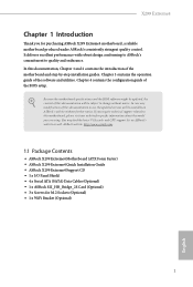
... and the BIOS software might be updated, the content of this documentation occur, the updated version will be available on ASRock's website as well. You may find the latest VGA cards and CPU support list on ASRock's website without notice. ASRock website http://www.asrock.com. 1.1 Package Contents • ASRock X299 Extreme4 Motherboard (ATX Form Factor) • ASRock X299 Extreme4 Quick...
... and the BIOS software might be updated, the content of this documentation occur, the updated version will be available on ASRock's website as well. You may find the latest VGA cards and CPU support list on ASRock's website without notice. ASRock website http://www.asrock.com. 1.1 Package Contents • ASRock X299 Extreme4 Motherboard (ATX Form Factor) • ASRock X299 Extreme4 Quick...

User Manual
Page 11
...• 1 x USB 3.1 Gen1 Header (Supports 2 USB 3.1 Gen1 ports) (Supports ESD Protection) • 1 x Performance Mode / Easy OC Header BIOS Feature • AMI UEFI Legal BIOS with multilingual GUI support • ACPI 6.1 Compliant wake up events • SMBIOS 3.0 Support • CPU, DRAM, VPPM, VTTM, PCH 1.0V, VCCIO,...8226; ErP/EuP ready (ErP/EuP ready power supply is in use. • 1 x 24 pin ATX Power Connector (Hi-Density Power Con- X299 Extreme4 * CPU_OPT/W_PUMP1, CHA_FAN1, CHA_FAN2 and CHA_ FAN3/W_PUMP2 can auto detect if 3-pin or 4-pin fan is required) 5 English tor) •...
...• 1 x USB 3.1 Gen1 Header (Supports 2 USB 3.1 Gen1 ports) (Supports ESD Protection) • 1 x Performance Mode / Easy OC Header BIOS Feature • AMI UEFI Legal BIOS with multilingual GUI support • ACPI 6.1 Compliant wake up events • SMBIOS 3.0 Support • CPU, DRAM, VPPM, VTTM, PCH 1.0V, VCCIO,...8226; ErP/EuP ready (ErP/EuP ready power supply is in use. • 1 x 24 pin ATX Power Connector (Hi-Density Power Con- X299 Extreme4 * CPU_OPT/W_PUMP1, CHA_FAN1, CHA_FAN2 and CHA_ FAN3/W_PUMP2 can auto detect if 3-pin or 4-pin fan is required) 5 English tor) •...

User Manual
Page 12
It should be done at your system. We are not responsible for possible damage caused by overclocking. 6 English * For detailed product information, please visit our website: http://www.asrock.com Please realize that there is a certain risk involved with overclocking, including adjusting the setting in the BIOS, applying Untied Overclocking Technology, or using third-party overclocking tools. Overclocking may affect your system's stability, or even cause damage to the components and devices of your own risk and expense.
It should be done at your system. We are not responsible for possible damage caused by overclocking. 6 English * For detailed product information, please visit our website: http://www.asrock.com Please realize that there is a certain risk involved with overclocking, including adjusting the setting in the BIOS, applying Untied Overclocking Technology, or using third-party overclocking tools. Overclocking may affect your system's stability, or even cause damage to the components and devices of your own risk and expense.

User Manual
Page 13
...USB3_4 USB 3.1 Gen2 T: USB31_TA_1 B: USB31_TC_1 CHA_FAN2 ATX12V1 ATX12V2 2066 Socket USB 2.0 T: USB1 Top: RJ-45 B: USB2 RoHS VROC1 RGB_LED2 X299 Extreme4 CPU_FAN1 CPU_OPT/W_PUMP1 1 1 DDR4_C2 (64 bit, 288-pin module) DDR4_C1 (64 bit, 288-pin module) DDR4_D2 (64 bit, 288-... Center: FRONT Bottom: MIC IN M2_1 USB3_5_6 PCIE1 M2_3 PCIE2 X299 EXTREME4 PCIE3 PCIE4 HD_AUDIO1 1 1 TPMS1 RGB_LED1 CLRMOS1 1 TB1 1 1 SATA3_0_1 Ultra M.2 PCIe Gen3 x4 1 Intel X299 SATA3_2_3 SATA3_4_5 M2_2 SATA3_6_7 BIOS CHA_FAN3/W_PUMP2 USB_3_4 1 USB_5_6 1 PM_EO 1 SPK_PLED1 CHA_FAN1 1 ...
...USB3_4 USB 3.1 Gen2 T: USB31_TA_1 B: USB31_TC_1 CHA_FAN2 ATX12V1 ATX12V2 2066 Socket USB 2.0 T: USB1 Top: RJ-45 B: USB2 RoHS VROC1 RGB_LED2 X299 Extreme4 CPU_FAN1 CPU_OPT/W_PUMP1 1 1 DDR4_C2 (64 bit, 288-pin module) DDR4_C1 (64 bit, 288-pin module) DDR4_D2 (64 bit, 288-... Center: FRONT Bottom: MIC IN M2_1 USB3_5_6 PCIE1 M2_3 PCIE2 X299 EXTREME4 PCIE3 PCIE4 HD_AUDIO1 1 1 TPMS1 RGB_LED1 CLRMOS1 1 TB1 1 1 SATA3_0_1 Ultra M.2 PCIe Gen3 x4 1 Intel X299 SATA3_2_3 SATA3_4_5 M2_2 SATA3_6_7 BIOS CHA_FAN3/W_PUMP2 USB_3_4 1 USB_5_6 1 PM_EO 1 SPK_PLED1 CHA_FAN1 1 ...

User Manual
Page 26
... jumper is removed. Clear CMOS Jumper (CLRMOS1) (see p.7, No. 26) 2-pin Jumper CLRMOS1 allows you to clear the CMOS when you just finish updating the BIOS, you must boot up the system first, and then shut it down before you do not clear the CMOS right after clearing the CMOS. However..., please do the clear-CMOS action. 2.5 Jumpers Setup The illustration shows how jumpers are setup. If you update the BIOS. Please be noted that the password, date, time, and user default profile will be cleared only if the CMOS battery is "Open".
... jumper is removed. Clear CMOS Jumper (CLRMOS1) (see p.7, No. 26) 2-pin Jumper CLRMOS1 allows you to clear the CMOS when you just finish updating the BIOS, you must boot up the system first, and then shut it down before you do not clear the CMOS right after clearing the CMOS. However..., please do the clear-CMOS action. 2.5 Jumpers Setup The illustration shows how jumpers are setup. If you update the BIOS. Please be noted that the password, date, time, and user default profile will be cleared only if the CMOS battery is "Open".

User Manual
Page 56
Step 3 Click Update to see more items you will see a list of recommended or critical updates for the BIOS or drivers. Step 1 Please check the item information before update. Click on Step 2 to start the update process. 50 English Click to select one or more details. 3.3.3 BIOS & Drivers Installing BIOS or Drivers When the "BIOS & Drivers" tab is selected, you want to update. Please update them all soon.
Step 3 Click Update to see more items you will see a list of recommended or critical updates for the BIOS or drivers. Step 1 Please check the item information before update. Click on Step 2 to start the update process. 50 English Click to select one or more details. 3.3.3 BIOS & Drivers Installing BIOS or Drivers When the "BIOS & Drivers" tab is selected, you want to update. Please update them all soon.

User Manual
Page 61
... screen to switch to Advanced Mode 55 English You can check the most crucial information of the system's current status. X299 Extreme4 4.2 EZ Mode The EZ Mode screen appears when you enter the BIOS setup program by default. EZ mode is a dashboard which contains multiple readings of your system, such as CPU speed...
... screen to switch to Advanced Mode 55 English You can check the most crucial information of the system's current status. X299 Extreme4 4.2 EZ Mode The EZ Mode screen appears when you enter the BIOS setup program by default. EZ mode is a dashboard which contains multiple readings of your system, such as CPU speed...

User Manual
Page 62
... settings Boot For configuring boot settings and boot priority Exit Exit the current screen or the UEFI Setup Utility English 56 Refer to configure the BIOS settings.
... settings Boot For configuring boot settings and boot priority Exit Exit the current screen or the UEFI Setup Utility English 56 Refer to configure the BIOS settings.

User Manual
Page 64
4.4 Main Screen When you enter the UEFI SETUP UTILITY, the Main screen will appear and display the system overview. My Favorite Display your collection of BIOS items. Press F5 to add/remove your favorite items. 58 English
4.4 Main Screen When you enter the UEFI SETUP UTILITY, the Main screen will appear and display the system overview. My Favorite Display your collection of BIOS items. Press F5 to add/remove your favorite items. 58 English

User Manual
Page 66
... to switch between multiple frequencies and voltage points for the CPU Mesh Domain. CPU Configuration All Core Ratio The maximum core ratio value that the BIOS will increase the internal CPU clock speed but also affect the clock speed of other components. Enabling will expose the CPPC v2 interface to allow...
... to switch between multiple frequencies and voltage points for the CPU Mesh Domain. CPU Configuration All Core Ratio The maximum core ratio value that the BIOS will increase the internal CPU clock speed but also affect the clock speed of other components. Enabling will expose the CPPC v2 interface to allow...


