
Intel Rapid Storage Guide
Page 12
... system onto a RAID volume, the RAID option must be enabled in the system BIOS. 1. Enable RAID in System BIOS Use the instructions included with your motherboard to enable RAID in the system BIOS, a RAID volume must be created, and the F6 installation method must be used to load the Intel®...
... system onto a RAID volume, the RAID option must be enabled in the system BIOS. 1. Enable RAID in System BIOS Use the instructions included with your motherboard to enable RAID in the system BIOS, a RAID volume must be created, and the F6 installation method must be used to load the Intel®...

RAID Installation Guide
Page 2
This section will guide you how to SATA Hard Disks Installation 1.1 Serial ATA (SATA) Hard Disks Installation Intel chipset supports Serial ATA (SATA) hard disks with RAID functions, including RAID 0, RAID 1, RAID 5, RAID 10 and Intel Rapid Storage. 1. You may install SATA hard disks on SATA ports. 2 Guide to create RAID on this guide carefully according to the Intel southbridge chipset that your motherboard adopts. Please read the RAID configurations in this motherboard for internal storage devices.
This section will guide you how to SATA Hard Disks Installation 1.1 Serial ATA (SATA) Hard Disks Installation Intel chipset supports Serial ATA (SATA) hard disks with RAID functions, including RAID 0, RAID 1, RAID 5, RAID 10 and Intel Rapid Storage. 1. You may install SATA hard disks on SATA ports. 2 Guide to create RAID on this guide carefully according to the Intel southbridge chipset that your motherboard adopts. Please read the RAID configurations in this motherboard for internal storage devices.

RAID Installation Guide
Page 3
For optimal performance, please install identical drives of RAID This motherboard adopts Intel southbridge chipset that integrates RAID controller supporting RAID 0 / RAID 1/ Intel Rapid Storage / RAID 10 / RAID 5 function with four independent Serial ATA (SATA) channels. ...
For optimal performance, please install identical drives of RAID This motherboard adopts Intel southbridge chipset that integrates RAID controller supporting RAID 0 / RAID 1/ Intel Rapid Storage / RAID 10 / RAID 5 function with four independent Serial ATA (SATA) channels. ...

RAID Installation Guide
Page 23
... than 2TB. STEP 1: Copy Intel® RAID drivers into a USB flash disk You can download the drivers from ASRock's website and unzip the files into a USB flash disk or copy the files from ASRock's motherboard support CD. (Please copy the files under the following directory: 32 bit: ..\i386\Win7_Intel.. 64-bit: ..\AMD64\Win7...
... than 2TB. STEP 1: Copy Intel® RAID drivers into a USB flash disk You can download the drivers from ASRock's website and unzip the files into a USB flash disk or copy the files from ASRock's motherboard support CD. (Please copy the files under the following directory: 32 bit: ..\i386\Win7_Intel.. 64-bit: ..\AMD64\Win7...

RAID Installation Guide
Page 25
...® 10 64-bit, install the hotfix kb2505454. (This may take about 5 minutes to reboot.) D. E. Reboot your system. (It may take more time to install motherboard drivers and utilities. 25 Please start to boot into Windows® or install driver/utilities. If you will install this link: http://support.microsoft.com...
...® 10 64-bit, install the hotfix kb2505454. (This may take about 5 minutes to reboot.) D. E. Reboot your system. (It may take more time to install motherboard drivers and utilities. 25 Please start to boot into Windows® or install driver/utilities. If you will install this link: http://support.microsoft.com...

Core-X CPU Support List
Page 1
... enterprise), and VROC (Intel® Virtual RAID on CPU), please refer to the official information released by Intel and the website driver update released by ASRock. Memory Configuration i7-7800X and above (Skylake-X CPU) 8 DIMMs working simultaneously When installing memory modules, the DIMM slots should be populated in the following order...
... enterprise), and VROC (Intel® Virtual RAID on CPU), please refer to the official information released by Intel and the website driver update released by ASRock. Memory Configuration i7-7800X and above (Skylake-X CPU) 8 DIMMs working simultaneously When installing memory modules, the DIMM slots should be populated in the following order...

User Manual
Page 2
...from any interference received, including interference that may appear in the documentation or product. This device complies with Part 15 of ASRock Inc. Operation is subject to infringe. Copyright Notice: No part of merchantability or fitness for loss of profits, loss of...for any indirect, special, incidental, or consequential damages (including damages for a particular purpose. With respect to the contents of this motherboard contains Perchlorate, a toxic substance controlled in advance. All rights reserved. Disclaimer: Specifications and information contained in any form or by...
...from any interference received, including interference that may appear in the documentation or product. This device complies with Part 15 of ASRock Inc. Operation is subject to infringe. Copyright Notice: No part of merchantability or fitness for loss of profits, loss of...for any indirect, special, incidental, or consequential damages (including damages for a particular purpose. With respect to the contents of this motherboard contains Perchlorate, a toxic substance controlled in advance. All rights reserved. Disclaimer: Specifications and information contained in any form or by...

User Manual
Page 4
Contents Chapter 1 Introduction 1 1.1 Package Contents 1 1.2 Specifications 2 1.3 Motherboard Layout 7 1.4 I/O Panel 9 Chapter 2 Installation 11 2.1 Installing the CPU 12 2.2 Installing the CPU Fan and Heatsink 15 2.3 Installation of Memory Modules (DIMM) 16 2.4 Expansion Slots (PCI ...
Contents Chapter 1 Introduction 1 1.1 Package Contents 1 1.2 Specifications 2 1.3 Motherboard Layout 7 1.4 I/O Panel 9 Chapter 2 Installation 11 2.1 Installing the CPU 12 2.2 Installing the CPU Fan and Heatsink 15 2.3 Installation of Memory Modules (DIMM) 16 2.4 Expansion Slots (PCI ...
User Manual
Page 7
... (Optional) • 1 x WiFi Bracket (Optional) 1 English ASRock website http://www.asrock.com. 1.1 Package Contents • ASRock X299 Extreme4 Motherboard (ATX Form Factor) • ASRock X299 Extreme4 Quick Installation Guide • ASRock X299 Extreme4 Support CD • 1 x I/O Panel Shield • 4 x Serial ATA (SATA) Data Cables (Optional) • 1 x ASRock SLI_HB_Bridge_2S Card (Optional) • 3 x Screws for purchasing ASRock X299 Extreme4 motherboard, a reliable motherboard produced under ASRock's consistently stringent quality control. If you...
... (Optional) • 1 x WiFi Bracket (Optional) 1 English ASRock website http://www.asrock.com. 1.1 Package Contents • ASRock X299 Extreme4 Motherboard (ATX Form Factor) • ASRock X299 Extreme4 Quick Installation Guide • ASRock X299 Extreme4 Support CD • 1 x I/O Panel Shield • 4 x Serial ATA (SATA) Data Cables (Optional) • 1 x ASRock SLI_HB_Bridge_2S Card (Optional) • 3 x Screws for purchasing ASRock X299 Extreme4 motherboard, a reliable motherboard produced under ASRock's consistently stringent quality control. If you...

User Manual
Page 13
1.3 Motherboard Layout PS2 Mouse PS2 Keyboard CLRC BTN1 USB 3.1 Gen1 T: USB3_1 B: USB3_2 USB 3.1 Gen1 T: USB3_3 B: USB3_4 USB 3.1 Gen2 T: USB31_TA_1 B: USB31_TC_1 CHA_FAN2 ATX12V1 ATX12V2 2066 Socket USB 2.0 T: USB1 Top: RJ-45 B: USB2 RoHS VROC1 RGB_LED2 X299 Extreme4 CPU_FAN1 CPU_OPT/W_PUMP1...Top: Center: FRONT Bottom: MIC IN M2_1 USB3_5_6 PCIE1 M2_3 PCIE2 X299 EXTREME4 PCIE3 PCIE4 HD_AUDIO1 1 1 TPMS1 RGB_LED1 CLRMOS1 1 TB1 1 1 SATA3_0_1 Ultra M.2 PCIe Gen3 x4 1 Intel X299 SATA3_2_3 SATA3_4_5 M2_2 SATA3_6_7 BIOS CHA_FAN3/W_PUMP2 USB_3_4 1 USB_5_6 1 PM_EO...
1.3 Motherboard Layout PS2 Mouse PS2 Keyboard CLRC BTN1 USB 3.1 Gen1 T: USB3_1 B: USB3_2 USB 3.1 Gen1 T: USB3_3 B: USB3_4 USB 3.1 Gen2 T: USB31_TA_1 B: USB31_TC_1 CHA_FAN2 ATX12V1 ATX12V2 2066 Socket USB 2.0 T: USB1 Top: RJ-45 B: USB2 RoHS VROC1 RGB_LED2 X299 Extreme4 CPU_FAN1 CPU_OPT/W_PUMP1...Top: Center: FRONT Bottom: MIC IN M2_1 USB3_5_6 PCIE1 M2_3 PCIE2 X299 EXTREME4 PCIE3 PCIE4 HD_AUDIO1 1 1 TPMS1 RGB_LED1 CLRMOS1 1 TB1 1 1 SATA3_0_1 Ultra M.2 PCIe Gen3 x4 1 Intel X299 SATA3_2_3 SATA3_4_5 M2_2 SATA3_6_7 BIOS CHA_FAN3/W_PUMP2 USB_3_4 1 USB_5_6 1 PM_EO...

User Manual
Page 17
... chassis, please do so may damage the motherboard. 11 English X299 Extreme4 Chapter 2 Installation This is an ATX form factor motherboard. Pre-installation Precautions Take note of your motherboard directly on a grounded anti-static pad or in the bag that the motherboard fits into it. Before you install the motherboard, study the configuration of the following precautions...
... chassis, please do so may damage the motherboard. 11 English X299 Extreme4 Chapter 2 Installation This is an ATX form factor motherboard. Pre-installation Precautions Take note of your motherboard directly on a grounded anti-static pad or in the bag that the motherboard fits into it. Before you install the motherboard, study the configuration of the following precautions...

User Manual
Page 20
6 A B 7 A B 8 Please save and replace the cover if the processor is removed. The cover must be placed if you wish to return the motherboard for after service. 14 English
6 A B 7 A B 8 Please save and replace the cover if the processor is removed. The cover must be placed if you wish to return the motherboard for after service. 14 English

User Manual
Page 22
...memory modules are installed in the DDR4 DIMM slots, then Dual Channel Memory Technology is activated. It will cause permanent damage to the motherboard and the DIMM if you always need to DDR4_C2.) • If only two memory modules are installed, then Triple Channel Memory ...and DDR4_D1 for first priority. For quad channel configuration, you force the DIMM into a DDR4 slot; 2.3 Installation of Memory Modules (DIMM) This motherboard provides eight 288-pin DDR4 (Double Data Rate 4) DIMM slots, and supports Quad Channel Memory Technology. 1. It is 16 activated. Quad Channel ...
...memory modules are installed in the DDR4 DIMM slots, then Dual Channel Memory Technology is activated. It will cause permanent damage to the motherboard and the DIMM if you always need to DDR4_C2.) • If only two memory modules are installed, then Triple Channel Memory ...and DDR4_D1 for first priority. For quad channel configuration, you force the DIMM into a DDR4 slot; 2.3 Installation of Memory Modules (DIMM) This motherboard provides eight 288-pin DDR4 (Double Data Rate 4) DIMM slots, and supports Quad Channel Memory Technology. 1. It is 16 activated. Quad Channel ...

User Manual
Page 24
.... PCIE4 (PCIe 3.0 x16 slot) is used for PCI Express x1 lane width cards. 2.4 Expansion Slots (PCI Express Slots) There are 4 PCI Express slots on the motherboard.
.... PCIE4 (PCIe 3.0 x16 slot) is used for PCI Express x1 lane width cards. 2.4 Expansion Slots (PCI Express Slots) There are 4 PCI Express slots on the motherboard.

User Manual
Page 25
English 19 PCIe Slot Configurations (For CPU with 28 PCIe lanes) PCIE2 PCIE3 PCIE4 Single Graphics Card x16 N/A N/A Two Graphics Cards in CrossFireXTM or SLITM Mode x16 x8 N/A PCIe Slot Configurations (For CPU with 16 PCIe lanes) PCIE2 PCIE3 PCIE4 Single Graphics Card x16 N/A N/A Two Graphics Cards in CrossFireXTM or SLITM Mode x8 x8 N/A X299 Extreme4 For a better thermal environment, please connect a chassis fan to the motherboard's chassis fan connector (CHA_FAN1, CHA_FAN2 or CHA_FAN3) when using multiple graphics cards.
English 19 PCIe Slot Configurations (For CPU with 28 PCIe lanes) PCIE2 PCIE3 PCIE4 Single Graphics Card x16 N/A N/A Two Graphics Cards in CrossFireXTM or SLITM Mode x16 x8 N/A PCIe Slot Configurations (For CPU with 16 PCIe lanes) PCIE2 PCIE3 PCIE4 Single Graphics Card x16 N/A N/A Two Graphics Cards in CrossFireXTM or SLITM Mode x8 x8 N/A X299 Extreme4 For a better thermal environment, please connect a chassis fan to the motherboard's chassis fan connector (CHA_FAN1, CHA_FAN2 or CHA_FAN3) when using multiple graphics cards.

User Manual
Page 27
You may differ by chassis. PLED (System Power LED): Connect to the motherboard. When connecting your system using the power switch. Placing jumper caps over these headers and connectors. The front panel design may configure the way to .... HDLED (Hard Drive Activity LED): Connect to the reset switch on the chassis front panel. Note the positive and negative pins before connecting the cables. X299 Extreme4 2.6 Onboard Headers and Connectors Onboard headers and connectors are matched correctly.
You may differ by chassis. PLED (System Power LED): Connect to the motherboard. When connecting your system using the power switch. Placing jumper caps over these headers and connectors. The front panel design may configure the way to .... HDLED (Hard Drive Activity LED): Connect to the reset switch on the chassis front panel. Note the positive and negative pins before connecting the cables. X299 Extreme4 2.6 Onboard Headers and Connectors Onboard headers and connectors are matched correctly.

User Manual
Page 28
...GND IntA_PB_SSTXIntA_PB_SSTX+ GND IntA_PB_DIntA_PB_D+ Dummy 1 There is occupied by a SATA-type M.2 device, SATA3_0 will be disabled. * If M2_2 is one header on this motherboard. USB 2.0 Headers (9-pin USB_3_4) (see p.7, No. 23) (9-pin USB_5_6) (see p.7, No. 22) USB_PWR PP+ GND DUMMY 1 GND P+ PUSB_PWR ...There are two headers on this motherboard. USB 3.1 Gen1 Header (19-pin USB3_5_6) (see p.7, No. 17) SPEAKER DUMMY DUMMY +5V 1 PLED+ PLED+ PLED- This USB 3.1 Gen1 header can...
...GND IntA_PB_SSTXIntA_PB_SSTX+ GND IntA_PB_DIntA_PB_D+ Dummy 1 There is occupied by a SATA-type M.2 device, SATA3_0 will be disabled. * If M2_2 is one header on this motherboard. USB 2.0 Headers (9-pin USB_3_4) (see p.7, No. 23) (9-pin USB_5_6) (see p.7, No. 22) USB_PWR PP+ GND DUMMY 1 GND P+ PUSB_PWR ...There are two headers on this motherboard. USB 3.1 Gen1 Header (19-pin USB3_5_6) (see p.7, No. 17) SPEAKER DUMMY DUMMY +5V 1 PLED+ PLED+ PLED- This USB 3.1 Gen1 header can...
User Manual
Page 29
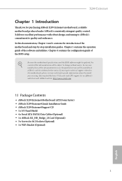
...OUT_RET are for connecting audio devices to the front audio panel. 1. To activate the front mic, go to install your system. 2. X299 Extreme4 Front Panel Audio Header (9-pin HD_AUDIO1) (see p.7, No. 29) GND PRESENCE# MIC_RET OUT_RET 1 OUT2_L J_SENSE OUT2_R MIC2_R MIC2_L This header... wire to Ground (GND). Chassis Fan Connectors (4-pin CHA_FAN1) (see p.7, No. 24) 4 3 2 1 FAN_SPEED_CONTROL CHA_FAN_SPEED FAN_VOLTAGE GND This motherboard provides a 4-Pin water cooling chassis fan connector. You don't need to function correctly. If you plan to connect a 3-Pin chassis water ...
...OUT_RET are for connecting audio devices to the front audio panel. 1. To activate the front mic, go to install your system. 2. X299 Extreme4 Front Panel Audio Header (9-pin HD_AUDIO1) (see p.7, No. 29) GND PRESENCE# MIC_RET OUT_RET 1 OUT2_L J_SENSE OUT2_R MIC2_R MIC2_L This header... wire to Ground (GND). Chassis Fan Connectors (4-pin CHA_FAN1) (see p.7, No. 24) 4 3 2 1 FAN_SPEED_CONTROL CHA_FAN_SPEED FAN_VOLTAGE GND This motherboard provides a 4-Pin water cooling chassis fan connector. You don't need to function correctly. If you plan to connect a 3-Pin chassis water ...

User Manual
Page 30
...Header (17-pin TPMS1) (see p.7, No. 28) FAN_SPEED_CONTROL CPU_FAN_SPEED FAN_VOLTAGE GND 1 2 34 This motherboard provides a 4-Pin CPU fan (Quiet Fan) connector. FAN_SPEED_CONTROL CPU_FAN_SPEED FAN_VOLTAGE GND 1 2 34 This motherboard provides a 4-Pin water cooling CPU fan connector. GND SMB_CLK_MAIN SMB_DATA_MAIN LAD2 LAD1 GND S_PWRDWN# SERIRQ# GND..., passwords, 1 and data. To use a 4-pin ATX power supply, please plug it to Pin 1-3. 12 24 1 13 This motherboard provides a 24-pin ATX power connector. To use a 20-pin ATX power supply, please plug it to Pin 1-3. A TPM system...
...Header (17-pin TPMS1) (see p.7, No. 28) FAN_SPEED_CONTROL CPU_FAN_SPEED FAN_VOLTAGE GND 1 2 34 This motherboard provides a 4-Pin CPU fan (Quiet Fan) connector. FAN_SPEED_CONTROL CPU_FAN_SPEED FAN_VOLTAGE GND 1 2 34 This motherboard provides a 4-Pin water cooling CPU fan connector. GND SMB_CLK_MAIN SMB_DATA_MAIN LAD2 LAD1 GND S_PWRDWN# SERIRQ# GND..., passwords, 1 and data. To use a 4-pin ATX power supply, please plug it to Pin 1-3. 12 24 1 13 This motherboard provides a 24-pin ATX power connector. To use a 20-pin ATX power supply, please plug it to Pin 1-3. A TPM system...

User Manual
Page 33
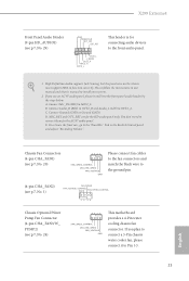
X299 Extreme4 2.7 Smart Switch The motherboard has a smart switch: Clear CMOS Button, allowing users to quickly clear the CMOS values. English 27 Clear CMOS Button (CLRCBTN) (see p.9, No. 14) Clear CMOS Button allows users to clear the CMOS values. This function is workable only when you power off your computer and unplug the power supply.
X299 Extreme4 2.7 Smart Switch The motherboard has a smart switch: Clear CMOS Button, allowing users to quickly clear the CMOS values. English 27 Clear CMOS Button (CLRCBTN) (see p.9, No. 14) Clear CMOS Button allows users to clear the CMOS values. This function is workable only when you power off your computer and unplug the power supply.

