User Manual
Page 8
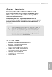
... notice. In case any modifications of the motherboard and step-by-step installation guides. ASRock website http://www.asrock.com. 1.1 Package Contents • ASRock X299 Creator Motherboard (ATX Form Factor) • ASRock X299 Creator Quick Installation Guide • ASRock X299 Creator Support CD • 1 x ASRock SLI_HB_Bridge_2S Card (Optional) • 1 x ASRock WiFi 2.4/5 GHz Antenna (Optional) • 4 x Serial ATA (SATA) Data Cables (Optional) • 3 x Screws for...
... notice. In case any modifications of the motherboard and step-by-step installation guides. ASRock website http://www.asrock.com. 1.1 Package Contents • ASRock X299 Creator Motherboard (ATX Form Factor) • ASRock X299 Creator Quick Installation Guide • ASRock X299 Creator Support CD • 1 x ASRock SLI_HB_Bridge_2S Card (Optional) • 1 x ASRock WiFi 2.4/5 GHz Antenna (Optional) • 4 x Serial ATA (SATA) Data Cables (Optional) • 3 x Screws for...

User Manual
Page 9
.../PCIE3/PCIE5 will run at x16/x8/x16/x8. If a M.2 PCI Express module is installed on ASRock's website for the LGA 2066 Socket (Cascade Lake-X, Skylake X Refresh and Skylake X) • Digi... 13 Power Phase design • Supports Intel® Turbo Boost Max Technology 3.0 Chipset • Intel® X299 Memory • Quad Channel DDR4 Memory Technology • 8 x DDR4 DIMM Slots • Supports DDR4 4200... on M2_1 and M2_2, PCIE2 will be disabled. 1.2 Specifications Platform CPU • ATX Form Factor • 8 Layer PCB • 2oz Copper PCB • Supports Intel® CoreTM ...
.../PCIE3/PCIE5 will run at x16/x8/x16/x8. If a M.2 PCI Express module is installed on ASRock's website for the LGA 2066 Socket (Cascade Lake-X, Skylake X Refresh and Skylake X) • Digi... 13 Power Phase design • Supports Intel® Turbo Boost Max Technology 3.0 Chipset • Intel® X299 Memory • Quad Channel DDR4 Memory Technology • 8 x DDR4 DIMM Slots • Supports DDR4 4200... on M2_1 and M2_2, PCIE2 will be disabled. 1.2 Specifications Platform CPU • ATX Form Factor • 8 Layer PCB • 2oz Copper PCB • Supports Intel® CoreTM ...

User Manual
Page 13
... fan of maximum 2A (24W) fan power. * CPU_FAN2/WP, CHA_FAN1~5/WP can auto detect if 3-pin or 4-pin fan is in use. • 1 x 24 pin ATX Power Connector (Hi-Density Power Con-
... fan of maximum 2A (24W) fan power. * CPU_FAN2/WP, CHA_FAN1~5/WP can auto detect if 3-pin or 4-pin fan is in use. • 1 x 24 pin ATX Power Connector (Hi-Density Power Con-

User Manual
Page 16
... Power Connector (ATX12V1) 5 Addressable LED Header (ADDR_LED2) 6 2 x 288-pin DDR4 DIMM Slots (DDR4_C2, DDR4_D2) 7 2 x 288-pin DDR4 DIMM Slots (DDR4_C1, DDR4_D1) 8 RGB LED Header (RGB_HEADER2) 9 ATX Power Connector (ATXPWR1) 10 Chassis / Waterpump Fan Connector (CHA_FAN1/WP) 11 CPU / Waterpump Fan Connector (CPU_FAN2/WP) 12 Front Panel Type C USB 3.2 Gen2 Header (USB32_TC1...) 32 RGB LED Header (RGB_HEADER1) 33 Virtual RAID On CPU Header (VROC1) 34 Chassis / Waterpump Fan Connector (CHA_FAN5/WP) 35 Front Panel Audio Header (HD_AUDIO1) X299 Creator 9 English No.
... Power Connector (ATX12V1) 5 Addressable LED Header (ADDR_LED2) 6 2 x 288-pin DDR4 DIMM Slots (DDR4_C2, DDR4_D2) 7 2 x 288-pin DDR4 DIMM Slots (DDR4_C1, DDR4_D1) 8 RGB LED Header (RGB_HEADER2) 9 ATX Power Connector (ATXPWR1) 10 Chassis / Waterpump Fan Connector (CHA_FAN1/WP) 11 CPU / Waterpump Fan Connector (CPU_FAN2/WP) 12 Front Panel Type C USB 3.2 Gen2 Header (USB32_TC1...) 32 RGB LED Header (RGB_HEADER1) 33 Virtual RAID On CPU Header (VROC1) 34 Chassis / Waterpump Fan Connector (CHA_FAN5/WP) 35 Front Panel Audio Header (HD_AUDIO1) X299 Creator 9 English No.

User Manual
Page 24
... fits into it. Also remember to use a grounded wrist strap or touch a safety grounded object before installing or removing the motherboard components. X299 Creator Chapter 2 Installation This is an ATX form factor motherboard. Doing so may cause physical injuries and damages to motherboard components. • In order to avoid damage from static electricity...
... fits into it. Also remember to use a grounded wrist strap or touch a safety grounded object before installing or removing the motherboard components. X299 Creator Chapter 2 Installation This is an ATX form factor motherboard. Doing so may cause physical injuries and damages to motherboard components. • In order to avoid damage from static electricity...

User Manual
Page 38
X299 Creator Chassis Water Pump Fan This motherboard Connectors FAN_SPEED provides five 4-Pin water FAN_VOLTAGE_CONTROL GND FAN_SPEED_CONTROL (4-pin CHA_FAN1/WP) cooling chassis fan (see p.8, No. 9) FAN_SPEED_CONTROL CPU_FAN_SPEED ... (4-pin CHA_FAN2/WP) (see p.8, No. 25) FAN_SPEED_CONTROL CHA_FAN_SPEED FAN_VOLTAGE GND 4 connect it to Pin 1-3. CPU Water Pump Fan Connector (4-pin CPU_FAN2/WP) (see p.8, No. 11) ATX Power Connector (24-pin ATXPWR1) (see p.8, No. 10) connectors. If you plan to connect a 3-Pin CPU fan, please connect it along Pin 1 and Pin 13...
X299 Creator Chassis Water Pump Fan This motherboard Connectors FAN_SPEED provides five 4-Pin water FAN_VOLTAGE_CONTROL GND FAN_SPEED_CONTROL (4-pin CHA_FAN1/WP) cooling chassis fan (see p.8, No. 9) FAN_SPEED_CONTROL CPU_FAN_SPEED ... (4-pin CHA_FAN2/WP) (see p.8, No. 25) FAN_SPEED_CONTROL CHA_FAN_SPEED FAN_VOLTAGE GND 4 connect it to Pin 1-3. CPU Water Pump Fan Connector (4-pin CPU_FAN2/WP) (see p.8, No. 11) ATX Power Connector (24-pin ATXPWR1) (see p.8, No. 10) connectors. If you plan to connect a 3-Pin CPU fan, please connect it along Pin 1 and Pin 13...

User Manual
Page 39
...effects. RGB LED Headers (4-pin RGB_HEADER1) (see p.8, No. 32) (4-pin RGB_HEADER2) (see p.8, No. 3) 8 5 This motherboard provides two 8-pin ATX 4 1 12V power connectors. otherwise, the cable may be damaged. *Please refer to page 67 for the CPU and not the graphics card. A ...also helps enhance network security, protects digital identities, and ensures platform integrity. Caution: Never install the RGB LED cable in the wrong orientation; English 32 ATX 12V Power Connectors (8-pin ATX12V1) (see p.8, No. 4) (8-pin ATX12V2) (see p.8, No. 8) 1 12V G R B These two RGB headers...
...effects. RGB LED Headers (4-pin RGB_HEADER1) (see p.8, No. 32) (4-pin RGB_HEADER2) (see p.8, No. 3) 8 5 This motherboard provides two 8-pin ATX 4 1 12V power connectors. otherwise, the cable may be damaged. *Please refer to page 67 for the CPU and not the graphics card. A ...also helps enhance network security, protects digital identities, and ensures platform integrity. Caution: Never install the RGB LED cable in the wrong orientation; English 32 ATX 12V Power Connectors (8-pin ATX12V1) (see p.8, No. 4) (8-pin ATX12V2) (see p.8, No. 8) 1 12V G R B These two RGB headers...