
RAID Installation Guide
Page 1
AMD BIOS RAID Installation Guide ...2 1.1 Introduction to RAID...2 1.2 RAID Configurations Precautions 4 1.3 Legacy RAID ROM Configuration 5 1.4 UEFI RAID Configuration ...11 2. AMD Windows RAID Installation Guide 16 1 AMD RAID Installation Guide 1.
AMD BIOS RAID Installation Guide ...2 1.1 Introduction to RAID...2 1.2 RAID Configurations Precautions 4 1.3 Legacy RAID ROM Configuration 5 1.4 UEFI RAID Configuration ...11 2. AMD Windows RAID Installation Guide 16 1 AMD RAID Installation Guide 1.

RAID Installation Guide
Page 2
...the same model and capacity when creating a RAID set the option to RAID mode by using the onboard FastBuild BIOS utility under BIOS environment. AMD BIOS RAID Installation Guide AMD BIOS RAID Installation Guide is called data mirroring that optimizes two identical hard disk drives to configure RAID functions by ... term "RAID" stands for you to read and write data in our support CD, then you make a SATA driver diskette, press or to enter BIOS setup to set . Hot-Plug any fault tolerance. RAID 1 (Data Mirroring) RAID 1 is a method combining two or more hard disk drives into...
...the same model and capacity when creating a RAID set the option to RAID mode by using the onboard FastBuild BIOS utility under BIOS environment. AMD BIOS RAID Installation Guide AMD BIOS RAID Installation Guide is called data mirroring that optimizes two identical hard disk drives to configure RAID functions by ... term "RAID" stands for you to read and write data in our support CD, then you make a SATA driver diskette, press or to enter BIOS setup to set . Hot-Plug any fault tolerance. RAID 1 (Data Mirroring) RAID 1 is a method combining two or more hard disk drives into...

RAID Installation Guide
Page 5
... delete the existing disk arrays before creating a new array. 5 B. To create a new array, press on the "Create Array" option. *Be sure to enter the RAID BIOS setup utility. Set the "SATA Mode" option to create and configure the RAID disk. STEP 1: Set up UEFI A. C. 1.3 Legacy RAID ROM Configuration Use legacy RAID...
... delete the existing disk arrays before creating a new array. 5 B. To create a new array, press on the "Create Array" option. *Be sure to enter the RAID BIOS setup utility. Set the "SATA Mode" option to create and configure the RAID disk. STEP 1: Set up UEFI A. C. 1.3 Legacy RAID ROM Configuration Use legacy RAID...

RAID Installation Guide
Page 7
Select a caching mode and press to exit the RAID BIOS utility. 7 Press to proceed. When completed, you will see the new array on the main screen. Press to confirm and then press to return to the previous screen.
Select a caching mode and press to exit the RAID BIOS utility. 7 Press to proceed. When completed, you will see the new array on the main screen. Press to confirm and then press to return to the previous screen.

Quick Installation Guide
Page 5
Motherboard Layout 1 23 BIOS _FB1 ATX12V1 LAN USB 3.2 Gen1 Top: T: USB1 RJ-45 B: USB2 (I211AT) TRX40 Taichi 456 ATX12V2 7 CPU_FAN1 ADDR_LED1 1 8 RGB_LED1 1 9 DDR4_A1 (64 bit, 288-pin module) DDR4_A2 (64 bit, 288-pin module) DDR4_B1 (64 ...SPK Bottom: Optical SPDIF Top: Center: FRONT Bottom: MIC IN 32 LAN 31 CPU_FAN2/WP PCIE1 CHA_FAN3 /WP WiFi-802.11ax Module BIOS ROM M2_WIFI_1 M2_1 PCIE2 1 AMD TRX40 SATA3_7_8 USB3_7_8 SATA3_5_6 SATA3_3_4 PCIE3 1 Purity SoundTM 4 USB3_5_6 M2_2 HD_AUDIO1 CLRMOS1 1 1 PCIE4 RGB_LED2 ADDR_LED2 1 CHA_FAN2 CHA_FAN1 /WP /WP...
Motherboard Layout 1 23 BIOS _FB1 ATX12V1 LAN USB 3.2 Gen1 Top: T: USB1 RJ-45 B: USB2 (I211AT) TRX40 Taichi 456 ATX12V2 7 CPU_FAN1 ADDR_LED1 1 8 RGB_LED1 1 9 DDR4_A1 (64 bit, 288-pin module) DDR4_A2 (64 bit, 288-pin module) DDR4_B1 (64 ...SPK Bottom: Optical SPDIF Top: Center: FRONT Bottom: MIC IN 32 LAN 31 CPU_FAN2/WP PCIE1 CHA_FAN3 /WP WiFi-802.11ax Module BIOS ROM M2_WIFI_1 M2_1 PCIE2 1 AMD TRX40 SATA3_7_8 USB3_7_8 SATA3_5_6 SATA3_3_4 PCIE3 1 Purity SoundTM 4 USB3_5_6 M2_2 HD_AUDIO1 CLRMOS1 1 1 PCIE4 RGB_LED2 ADDR_LED2 1 CHA_FAN2 CHA_FAN1 /WP /WP...

Quick Installation Guide
Page 7
... Out Port 10 USB 3.2 Gen2 Ports (USB31_1_2) 11 USB 3.2 Gen2x2 Type-C Port 12 USB 3.2 Gen1 Ports (USB3_3_4) 13 USB 3.2 Gen1 Ports (USB3_1_2)**** 14 BIOS Flashback Button 15 Antenna Ports (on I /O Panel 1 2 TRX40 Taichi 46 3 57 15 14 13 12 11 10 98 No. I /O Panel Shield) * There are two LEDs on each LAN port.
... Out Port 10 USB 3.2 Gen2 Ports (USB31_1_2) 11 USB 3.2 Gen2x2 Type-C Port 12 USB 3.2 Gen1 Ports (USB3_3_4) 13 USB 3.2 Gen1 Ports (USB3_1_2)**** 14 BIOS Flashback Button 15 Antenna Ports (on I /O Panel 1 2 TRX40 Taichi 46 3 57 15 14 13 12 11 10 98 No. I /O Panel Shield) * There are two LEDs on each LAN port.
Quick Installation Guide
Page 9
...; ASRock TRX40 Taichi Support CD • 4 x Serial ATA (SATA) Data Cables (Optional) • 1 x ASRock SLI_HB_Bridge_2S Card (Optional) • 1 x ASRock WiFi 2.4/5 GHz Antenna (Optional) • 1 x ASRock HYPER QUAD M.2 CARD (Optional) • 1 x ASRock Screwdriver (Optional) • 6 x Screws for M.2 Sockets (Optional) • 2 x Standoffs for purchasing ASRock TRX40 Taichi motherboard, a reliable motherboard produced under ASRock's consistently stringent quality control. Because the motherboard specifications and the BIOS...
...; ASRock TRX40 Taichi Support CD • 4 x Serial ATA (SATA) Data Cables (Optional) • 1 x ASRock SLI_HB_Bridge_2S Card (Optional) • 1 x ASRock WiFi 2.4/5 GHz Antenna (Optional) • 1 x ASRock HYPER QUAD M.2 CARD (Optional) • 1 x ASRock Screwdriver (Optional) • 6 x Screws for M.2 Sockets (Optional) • 2 x Standoffs for purchasing ASRock TRX40 Taichi motherboard, a reliable motherboard produced under ASRock's consistently stringent quality control. Because the motherboard specifications and the BIOS...

Quick Installation Guide
Page 12
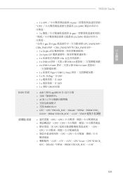
... ports. * ACPI wake-up function is not supported on USB3_1_2 ports. • 2 x RJ-45 LAN Ports with LED (ACT/LINK LED and SPEED LED) • 1 x BIOS Flashback Button • HD Audio Jacks: Rear Speaker / Central / Line in / Front Speaker / Microphone (Gold Audio Jacks) Storage • 8 x SATA3 6.0 Gb/s Connectors, support RAID (RAID...
... ports. * ACPI wake-up function is not supported on USB3_1_2 ports. • 2 x RJ-45 LAN Ports with LED (ACT/LINK LED and SPEED LED) • 1 x BIOS Flashback Button • HD Audio Jacks: Rear Speaker / Central / Line in / Front Speaker / Microphone (Gold Audio Jacks) Storage • 8 x SATA3 6.0 Gb/s Connectors, support RAID (RAID...

Quick Installation Guide
Page 14
... Monitor OS Certifications • AMI UEFI Legal BIOS with GUI support • Supports "Plug and Play" • ACPI 5.1 compliance wake up events • Supports jumperfree • SMBIOS 2.3 support • CPU, CPU VDDCR_SOC, DRAM, ...-bit • FCC, CE • ErP/EuP ready (ErP/EuP ready power supply is required) * For detailed product information, please visit our website: http://www.asrock.com English 10
... Monitor OS Certifications • AMI UEFI Legal BIOS with GUI support • Supports "Plug and Play" • ACPI 5.1 compliance wake up events • Supports jumperfree • SMBIOS 2.3 support • CPU, CPU VDDCR_SOC, DRAM, ...-bit • FCC, CE • ErP/EuP ready (ErP/EuP ready power supply is required) * For detailed product information, please visit our website: http://www.asrock.com English 10

Quick Installation Guide
Page 15
TRX40 Taichi Please realize that there is a certain risk involved with overclocking, including adjusting the setting in the BIOS, applying Untied Overclocking Technology, or using third-party overclocking tools. Overclocking may affect your system's stability, or even cause damage to the components and devices of your own risk and expense. We are not responsible for possible damage caused by overclocking. 11 English It should be done at your system.
TRX40 Taichi Please realize that there is a certain risk involved with overclocking, including adjusting the setting in the BIOS, applying Untied Overclocking Technology, or using third-party overclocking tools. Overclocking may affect your system's stability, or even cause damage to the components and devices of your own risk and expense. We are not responsible for possible damage caused by overclocking. 11 English It should be done at your system.

Quick Installation Guide
Page 31
... as system password, date, time, and system setup parameters. The data in CMOS. Please remember to clear the CMOS when you just finish updating the BIOS, you must boot up the system first, and then shut it down before you need to remove the jumper cap after clearing the CMOS. To... and unplug the power cord, then use a jumper cap to clear the data in CMOS includes system setup information such as the Clear CMOS jumper. TRX40 Taichi 2.5 Jumpers Setup The illustration shows how jumpers are setup. If no jumper cap is placed on the pins, the jumper is "Short".
... as system password, date, time, and system setup parameters. The data in CMOS. Please remember to clear the CMOS when you just finish updating the BIOS, you must boot up the system first, and then shut it down before you need to remove the jumper cap after clearing the CMOS. To... and unplug the power cord, then use a jumper cap to clear the data in CMOS includes system setup information such as the Clear CMOS jumper. TRX40 Taichi 2.5 Jumpers Setup The illustration shows how jumpers are setup. If no jumper cap is placed on the pins, the jumper is "Short".

Quick Installation Guide
Page 37
... (RSTBTN) (see p.1, No. 17) Clear CMOS Button allows users to quickly clear the CMOS values. TRX40 Taichi 2.7 Smart Switches The motherboard has four smart switches: Power Button, Reset Button, Clear CMOS Buttons and BIOS Flashback Button, allowing users to quickly turn on /off the system, reset the system, clear the CMOS ...values or flash the BIOS. Clear CMOS Button (CLRCBTN1) (see p.1, No. 20) Reset Reset Button allows users to quickly turn on /off your computer and unplug the power ...
... (RSTBTN) (see p.1, No. 17) Clear CMOS Button allows users to quickly clear the CMOS values. TRX40 Taichi 2.7 Smart Switches The motherboard has four smart switches: Power Button, Reset Button, Clear CMOS Buttons and BIOS Flashback Button, allowing users to quickly turn on /off the system, reset the system, clear the CMOS ...values or flash the BIOS. Clear CMOS Button (CLRCBTN1) (see p.1, No. 20) Reset Reset Button allows users to quickly turn on /off your computer and unplug the power ...

Quick Installation Guide
Page 38
...means that you to the USB BIOS Flashback port. Then plug your USB drive to flash the BIOS. Press the BIOS Flashback Switch for about three seconds. To use the USB BIOS Flashback function, Please follow the steps below. 1. ASRock BIOS Flashback feature allows you plug the... USB drive to update BIOS without CPU. Rename the file to...
...means that you to the USB BIOS Flashback port. Then plug your USB drive to flash the BIOS. Press the BIOS Flashback Switch for about three seconds. To use the USB BIOS Flashback function, Please follow the steps below. 1. ASRock BIOS Flashback feature allows you plug the... USB drive to update BIOS without CPU. Rename the file to...

Quick Installation Guide
Page 155
TRX40 Taichi 무선 LAN I/O • Intel® 802.11ax WiFi 모듈 • IEEE 802.11a/b/g/n/ax 2.4/5 GHz WiFi6 802.11ax (2.4Gbps 2 ( 송신 ) x 2 2 개 • ...; 4 개 (ESD USB 전원은 USB3_1_2 ACPI USB3_1_2 LED 장착 RJ-45 LAN 포트 2 개 (ACT/LINK LED 및 SPEED LED) • BIOS 1 개 • HD • SATA3 6.0 Gb/s 커넥터 8 개가 RAID (RAID 0, RAID 1 및 RAID 10), NCQ, AHCI • M 키 유형 2260/2280...
TRX40 Taichi 무선 LAN I/O • Intel® 802.11ax WiFi 모듈 • IEEE 802.11a/b/g/n/ax 2.4/5 GHz WiFi6 802.11ax (2.4Gbps 2 ( 송신 ) x 2 2 개 • ...; 4 개 (ESD USB 전원은 USB3_1_2 ACPI USB3_1_2 LED 장착 RJ-45 LAN 포트 2 개 (ACT/LINK LED 및 SPEED LED) • BIOS 1 개 • HD • SATA3 6.0 Gb/s 커넥터 8 개가 RAID (RAID 0, RAID 1 및 RAID 10), NCQ, AHCI • M 키 유형 2260/2280...

Quick Installation Guide
Page 157
TRX40 Taichi OS 인증 CPU, CPU CPU, CPU CPU CPU, CPU CPU, CPU 12V, +5V, +3.3V, CPU Vcore, CPU VDDCR_ SOC, DRAM, VPPM, PREM VDDCR_SOC, +1.8V • Microsoft® Windows® 10 64 비트 • FCC, CE • ErP/EuP ErP/EuP http://www.asrock.com BIOS Untied Overclocking Technology 한국어 153
TRX40 Taichi OS 인증 CPU, CPU CPU, CPU CPU CPU, CPU CPU, CPU 12V, +5V, +3.3V, CPU Vcore, CPU VDDCR_ SOC, DRAM, VPPM, PREM VDDCR_SOC, +1.8V • Microsoft® Windows® 10 64 비트 • FCC, CE • ErP/EuP ErP/EuP http://www.asrock.com BIOS Untied Overclocking Technology 한국어 153

Quick Installation Guide
Page 165
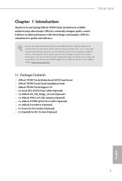
ASRock BIOS http://www.asrock.com. 2. BIOS 3 LED 8. LED BIOS *LED BIOS USB USB BIOS 한국어 USB BIOS 161 BIOS 4 creative.rom X USB 5. 24 AC 6. 이제 USB USB BIOS 7. BIOS 파일을 USB USB FAT32 3. TRX40 Taichi BIOS BIOS_FB1) (3 14 BIOS BIOS ASRock BIOS CPU 없이도 BIOS USB BIOS 1.
ASRock BIOS http://www.asrock.com. 2. BIOS 3 LED 8. LED BIOS *LED BIOS USB USB BIOS 한국어 USB BIOS 161 BIOS 4 creative.rom X USB 5. 24 AC 6. 이제 USB USB BIOS 7. BIOS 파일을 USB USB FAT32 3. TRX40 Taichi BIOS BIOS_FB1) (3 14 BIOS BIOS ASRock BIOS CPU 없이도 BIOS USB BIOS 1.
Quick Installation Guide
Page 179
...;εςϜ͕ FAT32 3. BIOS Flashback 3 LED 8. BIOS 4 creative.rom X: USB 5. 24 AC 6. ࣍ʹɺUSB υϥΠϒΛ USB BIOS Flashback 7. TRX40 Taichi BIOS BIOS_FB1) ʢp.3ɺNo. 14 ࢀর ) BIOS BIOS ASRock BIOS Flashback CPU BIOS USB BIOS Flashback 1. ASRock BIOS http://www.asrock.com. 2. LED BIOS LED ͳΓ·͢ɻ *LED BIOS Flashback USB υϥΠ...
...;εςϜ͕ FAT32 3. BIOS Flashback 3 LED 8. BIOS 4 creative.rom X: USB 5. 24 AC 6. ࣍ʹɺUSB υϥΠϒΛ USB BIOS Flashback 7. TRX40 Taichi BIOS BIOS_FB1) ʢp.3ɺNo. 14 ࢀর ) BIOS BIOS ASRock BIOS Flashback CPU BIOS USB BIOS Flashback 1. ASRock BIOS http://www.asrock.com. 2. LED BIOS LED ͳΓ·͢ɻ *LED BIOS Flashback USB υϥΠ...

Quick Installation Guide
Page 183
TRX40 Taichi 简体中文 无线 LAN 后面板 I/O • Intel® 802.11ax WiFi IEEE 802.11a/b/g/n/ax 2.4/5 GHz WiFi6 802.11ax (2.4Gbps) &#...;支持 ESD 4 x USB 3.2 Gen1 ESD 保护 ) * USB3_1_2 USB USB3_1_2 ACPI 2 x RJ-45 LAN LED(ACT/LINK LED 和 SPEED LED) • 1 x BIOS • 8 x SATA3 6.0 Gb/s RAID (RAID 0、RAID 1 和 RAID 10)、NCQ、AHCI • 1 x Hyper M.2 插槽 (M2_1),支持 M 键型 2260...
TRX40 Taichi 简体中文 无线 LAN 后面板 I/O • Intel® 802.11ax WiFi IEEE 802.11a/b/g/n/ax 2.4/5 GHz WiFi6 802.11ax (2.4Gbps) &#...;支持 ESD 4 x USB 3.2 Gen1 ESD 保护 ) * USB3_1_2 USB USB3_1_2 ACPI 2 x RJ-45 LAN LED(ACT/LINK LED 和 SPEED LED) • 1 x BIOS • 8 x SATA3 6.0 Gb/s RAID (RAID 0、RAID 1 和 RAID 10)、NCQ、AHCI • 1 x Hyper M.2 插槽 (M2_1),支持 M 键型 2260...
Quick Installation Guide
Page 193
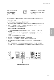
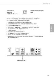
TRX40 Taichi BIOS BIOS_FB1) (见第 3 页,第 14 个 ) BIOS BIOS。 借助 ASRock BIOS CPU BIOS。 要使用 USB BIOS 1. 从 ASRock BIOS 文件:http://www.asrock.com。 2. 将 BIOS USB USB FAT32。 3 BIOS 文件。 4 creative.rom X USB 5. 将 24 6. 然后将 USB USB BIOS 7. 按住 BIOS LED 8. 等待 LED BIOS * 如果 LED BIOS USB USB BIOS 简体中文 USB BIOS 189
TRX40 Taichi BIOS BIOS_FB1) (见第 3 页,第 14 个 ) BIOS BIOS。 借助 ASRock BIOS CPU BIOS。 要使用 USB BIOS 1. 从 ASRock BIOS 文件:http://www.asrock.com。 2. 将 BIOS USB USB FAT32。 3 BIOS 文件。 4 creative.rom X USB 5. 将 24 6. 然后将 USB USB BIOS 7. 按住 BIOS LED 8. 等待 LED BIOS * 如果 LED BIOS USB USB BIOS 简体中文 USB BIOS 189
Quick Installation Guide
Page 199
繁體中文 TRX40 Taichi BIOS • 1 x CPU 4-pin CPU 2A (24W • 3 x 4-pin 2A (24W * 如果 3-pin 或 4-pin CPU_FAN2/WP、 CHA_FAN1/WP、CHA_FAN2/WP 和 CHA_FAN3... 1 x 前面板 Type C USB 3.2 Gen2 1 x Dr. Debug,含 LED • 1 x LED • 1 x LED • 1 x 清除 CMOS 按鈕 • AMI UEFI Legal BIOS 含 GUI ACPI 5.1 SMBIOS 2.3 • CPU、CPU VDDCR_SOC、DRAM、VPPM、PREM VDD_ CLDO、PERM VDDCR_SOC、+1.8V、VDDP CPU...
繁體中文 TRX40 Taichi BIOS • 1 x CPU 4-pin CPU 2A (24W • 3 x 4-pin 2A (24W * 如果 3-pin 或 4-pin CPU_FAN2/WP、 CHA_FAN1/WP、CHA_FAN2/WP 和 CHA_FAN3... 1 x 前面板 Type C USB 3.2 Gen2 1 x Dr. Debug,含 LED • 1 x LED • 1 x LED • 1 x 清除 CMOS 按鈕 • AMI UEFI Legal BIOS 含 GUI ACPI 5.1 SMBIOS 2.3 • CPU、CPU VDDCR_SOC、DRAM、VPPM、PREM VDD_ CLDO、PERM VDDCR_SOC、+1.8V、VDDP CPU...


