
RAID Installation Guide
Page 2
Although RAID 0 function can start to use the onboard RAID Option ROM Utility to configure RAID. 1.1 Introduction to RAID The term "RAID" stands for you to configure RAID functions by following the detailed instruction of the "User Manual" in our support CD, then you make a SATA driver diskette, press or to enter BIOS setup to the entire system since it will double the data transfer rate of a single disk alone while the two hard disks perform the...
Although RAID 0 function can start to use the onboard RAID Option ROM Utility to configure RAID. 1.1 Introduction to RAID The term "RAID" stands for you to configure RAID functions by following the detailed instruction of the "User Manual" in our support CD, then you make a SATA driver diskette, press or to enter BIOS setup to the entire system since it will double the data transfer rate of a single disk alone while the two hard disks perform the...

RAID Installation Guide
Page 8
... to enter UEFI setup utility. Insert the Support CD into one of the USB port. Please download the "SATA Floppy Imaged driver" from ASRock's website A. Please install the DVD-ROM. STEP 3.2: Download driver from ASRock's website and unzip the file into your USB flash drive. 8 B. E. D. A. During Windows installation process, when Disk selection page show up, please click . Click to find the driver inside your USB flash disk. B. STEP 4: Windows installation A. Plug a USB drive into the DVD-ROM drive. C. STEP 3.1: Copy RAID driver to a USB flash drive You...
... to enter UEFI setup utility. Insert the Support CD into one of the USB port. Please download the "SATA Floppy Imaged driver" from ASRock's website A. Please install the DVD-ROM. STEP 3.2: Download driver from ASRock's website and unzip the file into your USB flash drive. 8 B. E. D. A. During Windows installation process, when Disk selection page show up, please click . Click to find the driver inside your USB flash disk. B. STEP 4: Windows installation A. Plug a USB drive into the DVD-ROM drive. C. STEP 3.1: Copy RAID driver to a USB flash drive You...

RAID Installation Guide
Page 12
...;RAIDXpert2 Configuration UtilityArray ManagementCreate Array Select Physical DisksCheck AllApply ChangesCreate Array. *Be sure to Tools Easy RAID Installer F. Please download the "SATA Floppy Imaged driver" from ASRock's website A. G. Insert the Support CD into one of the USB port. A. Please install the DVD-ROM. Click to save to finish the driver copy process. Plug a USB drive into the DVD-ROM drive. Follow instructions to...
...;RAIDXpert2 Configuration UtilityArray ManagementCreate Array Select Physical DisksCheck AllApply ChangesCreate Array. *Be sure to Tools Easy RAID Installer F. Please download the "SATA Floppy Imaged driver" from ASRock's website A. G. Insert the Support CD into one of the USB port. A. Please install the DVD-ROM. Click to save to finish the driver copy process. Plug a USB drive into the DVD-ROM drive. Follow instructions to...

Quick Installation Guide
Page 5
...-pin module) DDR4_C1 (64 bit, 288-pin module) PS2 Keyboard /Mouse USB 3.2 Gen1 T: USB3 B: USB4 USB 3.2 Gen2x2 USB32_TC1 USB 3.2 Gen2 Top: T: USB1 2.5GLAN (Dragon B: USB2 RTL8125AG) Top: F_USB31_TC_1 Central/Bass LINE IN Center: REAR SPK Bottom: Optical SPDIF Top: Center: FRONT Bottom: MIC IN 32 LAN 31 CPU_FAN2/WP PCIE1 CHA_FAN3 /WP WiFi-802.11ax Module BIOS ROM M2_WIFI_1 M2_1 PCIE2 1 AMD TRX40...
...-pin module) DDR4_C1 (64 bit, 288-pin module) PS2 Keyboard /Mouse USB 3.2 Gen1 T: USB3 B: USB4 USB 3.2 Gen2x2 USB32_TC1 USB 3.2 Gen2 Top: T: USB1 2.5GLAN (Dragon B: USB2 RTL8125AG) Top: F_USB31_TC_1 Central/Bass LINE IN Center: REAR SPK Bottom: Optical SPDIF Top: Center: FRONT Bottom: MIC IN 32 LAN 31 CPU_FAN2/WP PCIE1 CHA_FAN3 /WP WiFi-802.11ax Module BIOS ROM M2_WIFI_1 M2_1 PCIE2 1 AMD TRX40...

Quick Installation Guide
Page 6
...USB 3.2 Gen1 Header (USB3_5_6) 17 Clear CMOS Button (CLRCBTN1) 18 System Panel Header (PANEL1) 19 Power Button (PWRBTN1) 20 Reset Button (RSTBTN1) 21 SATA3 Connector (SATA3_2) 22 SATA3 Connector (SATA3_1) 23 USB 2.0 Header (USB_1_2) 24 Power LED and Speaker Header (SPK_PLED1) 25 Chassis / Waterpump Fan Connector (CHA_FAN1/WP) 26 Chassis / Waterpump Fan Connector (CHA_FAN2/WP) 27 Addressable LED Header (ADDR_LED2) 28 RGB LED Header (RGB_LED2) 29 Clear CMOS Jumper (CLRMOS1) 30 Front Panel Audio Header (HD_AUDIO1) 31 Chassis / Waterpump Fan Connector (CHA_FAN3/WP) 32 CPU / Waterpump Fan Connector...
...USB 3.2 Gen1 Header (USB3_5_6) 17 Clear CMOS Button (CLRCBTN1) 18 System Panel Header (PANEL1) 19 Power Button (PWRBTN1) 20 Reset Button (RSTBTN1) 21 SATA3 Connector (SATA3_2) 22 SATA3 Connector (SATA3_1) 23 USB 2.0 Header (USB_1_2) 24 Power LED and Speaker Header (SPK_PLED1) 25 Chassis / Waterpump Fan Connector (CHA_FAN1/WP) 26 Chassis / Waterpump Fan Connector (CHA_FAN2/WP) 27 Addressable LED Header (ADDR_LED2) 28 RGB LED Header (RGB_LED2) 29 Clear CMOS Jumper (CLRMOS1) 30 Front Panel Audio Header (HD_AUDIO1) 31 Chassis / Waterpump Fan Connector (CHA_FAN3/WP) 32 CPU / Waterpump Fan Connector...
Quick Installation Guide
Page 19
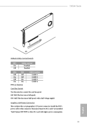
... (The fan runs at half speed, with higher power consumption 15 English Install the PSU's power cable to control the card fan speed. TRX40 Taichi ASRock Utility Control Switch SW1 Utility control On Disabled Off Enabled SW2 Off On Off On SW3 Off Off On On CARD number CARD 1 CARD 2 CARD 3 CARD 4 SW4: no function Card Fan Switch Use this switch to this connector when more than two M.2 cards* are installed. *Intel Optane SSD 900P or other M.2 card with a half voltage supply) Graphics 12V Power Connector This card provides a 6-pin graphics 12V power connector.
... (The fan runs at half speed, with higher power consumption 15 English Install the PSU's power cable to control the card fan speed. TRX40 Taichi ASRock Utility Control Switch SW1 Utility control On Disabled Off Enabled SW2 Off On Off On SW3 Off Off On On CARD number CARD 1 CARD 2 CARD 3 CARD 4 SW4: no function Card Fan Switch Use this switch to this connector when more than two M.2 cards* are installed. *Intel Optane SSD 900P or other M.2 card with a half voltage supply) Graphics 12V Power Connector This card provides a 6-pin graphics 12V power connector.

Quick Installation Guide
Page 34
...) USB Type-C Cable There is one Front Panel Type C USB 3.2 Gen2 Header on the chassis must support HDA to the front panel audio header by the steps below: A. Front Panel Type C USB 3.2 Gen2 Header (20-pin F_USB31_TC_1) (see p.1, No. 31) GND FAN_VOLTAGE FAN_SPEED This motherboard provides three 4-Pin water FAN_SPEED_CONTROL cooling chassis fan 1 2 34 connectors. Front Panel Audio Header (9-pin HD_AUDIO1) (see p.1, No. 30) GND PRESENCE# MIC_RET OUT_RET 1 OUT2_L J_SENSE OUT2_R MIC2_R MIC2_L This header is used for connecting a USB...
...) USB Type-C Cable There is one Front Panel Type C USB 3.2 Gen2 Header on the chassis must support HDA to the front panel audio header by the steps below: A. Front Panel Type C USB 3.2 Gen2 Header (20-pin F_USB31_TC_1) (see p.1, No. 31) GND FAN_VOLTAGE FAN_SPEED This motherboard provides three 4-Pin water FAN_SPEED_CONTROL cooling chassis fan 1 2 34 connectors. Front Panel Audio Header (9-pin HD_AUDIO1) (see p.1, No. 30) GND PRESENCE# MIC_RET OUT_RET 1 OUT2_L J_SENSE OUT2_R MIC2_R MIC2_L This header is used for connecting a USB...

Quick Installation Guide
Page 35
...use a 20-pin ATX power supply, please plug it along Pin 1 and Pin 13. 8 5 This motherboard provides two 8-pin ATX 12V power connectors. To use a 4-pin ATX power supply, please plug it along Pin 1 and Pin 5. *Warning: Please make sure that the power cable connected is for the CPU and not the graphics card. FAN_SPEED_CONTROL CPU_FAN_SPEED FAN_VOLTAGE GND 1 2 34 This motherboard provides a 4-Pin water cooling CPU fan connector. If you plan to connect a 3-Pin CPU fan, please connect it to this connector. TRX40 Taichi CPU Fan Connector (4-pin CPU_FAN1) (see p.1, No. 7) CPU...
...use a 20-pin ATX power supply, please plug it along Pin 1 and Pin 13. 8 5 This motherboard provides two 8-pin ATX 12V power connectors. To use a 4-pin ATX power supply, please plug it along Pin 1 and Pin 5. *Warning: Please make sure that the power cable connected is for the CPU and not the graphics card. FAN_SPEED_CONTROL CPU_FAN_SPEED FAN_VOLTAGE GND 1 2 34 This motherboard provides a 4-Pin water cooling CPU fan connector. If you plan to connect a 3-Pin CPU fan, please connect it to this connector. TRX40 Taichi CPU Fan Connector (4-pin CPU_FAN1) (see p.1, No. 7) CPU...

Quick Installation Guide
Page 38
... port. English USB BIOS Flashback port 34 ASRock BIOS Flashback feature allows you plug the USB drive to update BIOS without powering on the power supply's AC switch. *There is not operating properly. Extract BIOS file from ASRock's website : http://www.asrock.com. 2. Rename the file to "creative.rom" and save it to the motherboard. Plug the 24 pin power connector to the root directory of your USB flash drive must be FAT32. 3. Then turn on the system, even without CPU. Download...
... port. English USB BIOS Flashback port 34 ASRock BIOS Flashback feature allows you plug the USB drive to update BIOS without powering on the power supply's AC switch. *There is not operating properly. Extract BIOS file from ASRock's website : http://www.asrock.com. 2. Rename the file to "creative.rom" and save it to the motherboard. Plug the 24 pin power connector to the root directory of your USB flash drive must be FAT32. 3. Then turn on the system, even without CPU. Download...

User Manual
Page 5
...Contents 1 1.2 Specifications 2 1.3 Motherboard Layout 7 1.4 I/O Panel 9 1.5 WiFi-802.11ax Module and ASRock WiFi 2.4/5 GHz Antenna 11 1.6 ASRock HYPER QUAD M.2 CARD 12 Chapter 2 Installation 16 2.1 Installing the CPU 17 2.2 Installing the CPU Liquid Cooler 21 2.3 Installation of Memory Modules (DIMM) 23 2.4 Expansion Slots (PCI Express Slots) 25 2.5 Jumpers Setup 26 2.6 Onboard Headers and Connectors 27 2.7 Smart Switches 32 2.8 Dr. Debug 34 2.9 SLITM and 3-Way SLITM Operation Guide 40 2.9.1 Installing Two SLITM-Ready Graphics Cards 40 2.9.2 Installing Three...
...Contents 1 1.2 Specifications 2 1.3 Motherboard Layout 7 1.4 I/O Panel 9 1.5 WiFi-802.11ax Module and ASRock WiFi 2.4/5 GHz Antenna 11 1.6 ASRock HYPER QUAD M.2 CARD 12 Chapter 2 Installation 16 2.1 Installing the CPU 17 2.2 Installing the CPU Liquid Cooler 21 2.3 Installation of Memory Modules (DIMM) 23 2.4 Expansion Slots (PCI Express Slots) 25 2.5 Jumpers Setup 26 2.6 Onboard Headers and Connectors 27 2.7 Smart Switches 32 2.8 Dr. Debug 34 2.9 SLITM and 3-Way SLITM Operation Guide 40 2.9.1 Installing Two SLITM-Ready Graphics Cards 40 2.9.2 Installing Three...
User Manual
Page 8
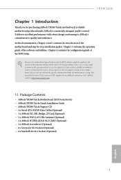
... the configuration guide of the software and utilities. TRX40 Taichi Chapter 1 Introduction Thank you for M.2 Sockets (Optional) 1 English In case any modifications of the motherboard and step-by-step installation guides. You may find the latest VGA cards and CPU support list on ASRock's website without notice. Chapter 3 contains the operation guide of the BIOS setup. In this documentation, Chapter 1 and 2 contains the introduction of this motherboard, please visit our website for specific...
... the configuration guide of the software and utilities. TRX40 Taichi Chapter 1 Introduction Thank you for M.2 Sockets (Optional) 1 English In case any modifications of the motherboard and step-by-step installation guides. You may find the latest VGA cards and CPU support list on ASRock's website without notice. Chapter 3 contains the operation guide of the BIOS setup. In this documentation, Chapter 1 and 2 contains the introduction of this motherboard, please visit our website for specific...

User Manual
Page 15
...USB 3.2 Gen1 Header (USB3_5_6) 17 Clear CMOS Button (CLRCBTN1) 18 System Panel Header (PANEL1) 19 Power Button (PWRBTN1) 20 Reset Button (RSTBTN1) 21 SATA3 Connector (SATA3_2) 22 SATA3 Connector (SATA3_1) 23 USB 2.0 Header (USB_1_2) 24 Power LED and Speaker Header (SPK_PLED1) 25 Chassis / Waterpump Fan Connector (CHA_FAN1/WP) 26 Chassis / Waterpump Fan Connector (CHA_FAN2/WP) 27 Addressable LED Header (ADDR_LED2) 28 RGB LED Header (RGB_LED2) 29 Clear CMOS Jumper (CLRMOS1) 30 Front Panel Audio Header (HD_AUDIO1) 31 Chassis / Waterpump Fan Connector (CHA_FAN3/WP) 32 CPU / Waterpump Fan Connector...
...USB 3.2 Gen1 Header (USB3_5_6) 17 Clear CMOS Button (CLRCBTN1) 18 System Panel Header (PANEL1) 19 Power Button (PWRBTN1) 20 Reset Button (RSTBTN1) 21 SATA3 Connector (SATA3_2) 22 SATA3 Connector (SATA3_1) 23 USB 2.0 Header (USB_1_2) 24 Power LED and Speaker Header (SPK_PLED1) 25 Chassis / Waterpump Fan Connector (CHA_FAN1/WP) 26 Chassis / Waterpump Fan Connector (CHA_FAN2/WP) 27 Addressable LED Header (ADDR_LED2) 28 RGB LED Header (RGB_LED2) 29 Clear CMOS Jumper (CLRMOS1) 30 Front Panel Audio Header (HD_AUDIO1) 31 Chassis / Waterpump Fan Connector (CHA_FAN3/WP) 32 CPU / Waterpump Fan Connector...

User Manual
Page 21
... (The fan runs at half speed, with higher power consumption English 14 Install the PSU's power cable to this switch to control the card fan speed. ASRock Utility Control Switch SW1 On Off Utility control Disabled Enabled SW2 Off On Off On SW3 Off Off On On SW4: no function CARD number CARD 1 CARD 2 CARD 3 CARD 4 Card Fan Switch Use this connector when more than two M.2 cards* are installed. *Intel Optane SSD 900P or other M.2 card with a half voltage supply) Graphics 12V Power Connector This card provides a 6-pin graphics 12V power connector.
... (The fan runs at half speed, with higher power consumption English 14 Install the PSU's power cable to this switch to control the card fan speed. ASRock Utility Control Switch SW1 On Off Utility control Disabled Enabled SW2 Off On Off On SW3 Off Off On On SW4: no function CARD number CARD 1 CARD 2 CARD 3 CARD 4 Card Fan Switch Use this connector when more than two M.2 cards* are installed. *Intel Optane SSD 900P or other M.2 card with a half voltage supply) Graphics 12V Power Connector This card provides a 6-pin graphics 12V power connector.

User Manual
Page 40
TRX40 Taichi BIOS Flashback Button (BIOS_FB1) (see p.9, No. 14) BIOS Flashback Switch allows users to the motherboard. Extract BIOS file from ASRock's website : http://www.asrock.com. 2. Rename the file to "creative.rom" and save it to power on the system, even without CPU. Then turn on the power supply's AC switch. *There is not operating properly. Then plug your USB flash drive. English USB BIOS Flashback port 33 ASRock BIOS Flashback feature allows you plug the USB drive to update BIOS without powering on the...
TRX40 Taichi BIOS Flashback Button (BIOS_FB1) (see p.9, No. 14) BIOS Flashback Switch allows users to the motherboard. Extract BIOS file from ASRock's website : http://www.asrock.com. 2. Rename the file to "creative.rom" and save it to power on the system, even without CPU. Then turn on the power supply's AC switch. *There is not operating properly. Then plug your USB flash drive. English USB BIOS Flashback port 33 ASRock BIOS Flashback feature allows you plug the USB drive to update BIOS without powering on the...
User Manual
Page 52
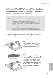
... other graphics card to the AMD's website for details.) English 45 Download the drivers from the AMD's website: www.amd.com 3. Please refer to enable CrossFireXTM. CrossFire Bridge Step 2 Connect two graphics cards by installing a CrossFire Bridge on the CrossFire Bridge Interconnects on the slots. Different CrossFireXTM cards may require different methods to your graphics card vendor for details. 4. TRX40 Taichi 2.10 CrossFireXTM and 3-Way CrossFireXTM Operation Guide This motherboard supports...
... other graphics card to the AMD's website for details.) English 45 Download the drivers from the AMD's website: www.amd.com 3. Please refer to enable CrossFireXTM. CrossFire Bridge Step 2 Connect two graphics cards by installing a CrossFire Bridge on the CrossFire Bridge Interconnects on the slots. Different CrossFireXTM cards may require different methods to your graphics card vendor for details. 4. TRX40 Taichi 2.10 CrossFireXTM and 3-Way CrossFireXTM Operation Guide This motherboard supports...
User Manual
Page 55
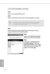
... pane, click Performance and then AMD CrossFireXTM. We recommend using this utility to installation. English 48 The Catalyst Uninstaller is an optional download. Step 2 Remove the AMD drivers if you have any previously installed Catalyst drivers prior to uninstall any VGA drivers installed in the Windows® system tray. AMD Catalyst Control Center Step 4 Double-click the AMD Catalyst Control Center icon in your computer. Please check AMD's website for AMD driver updates.
... pane, click Performance and then AMD CrossFireXTM. We recommend using this utility to installation. English 48 The Catalyst Uninstaller is an optional download. Step 2 Remove the AMD drivers if you have any previously installed Catalyst drivers prior to uninstall any VGA drivers installed in the Windows® system tray. AMD Catalyst Control Center Step 4 Double-click the AMD Catalyst Control Center icon in your computer. Please check AMD's website for AMD driver updates.
User Manual
Page 62
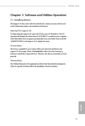
Utilities Menu The Utilities Menu shows the application software that enhance the motherboard's features. TRX40 Taichi Chapter 3 Software and Utilities Operation 3.1 Installing Drivers The Support CD that comes with the motherboard contains necessary drivers and useful utilities that the motherboard supports. Drivers Menu The drivers compatible to install those required drivers. Therefore, the drivers you install can work properly. If the Main Menu does not appear automatically, locate and double click on the support CD driver page. Click on a specific item then follow the...
Utilities Menu The Utilities Menu shows the application software that enhance the motherboard's features. TRX40 Taichi Chapter 3 Software and Utilities Operation 3.1 Installing Drivers The Support CD that comes with the motherboard contains necessary drivers and useful utilities that the motherboard supports. Drivers Menu The drivers compatible to install those required drivers. Therefore, the drivers you install can work properly. If the Main Menu does not appear automatically, locate and double click on the support CD driver page. Click on a specific item then follow the...

User Manual
Page 79
... Configuration Voltage Configuration CPU Vcore Voltage Configure the voltage for DDR4 modules. CLDO VDDP Voltage Control VDDP is set based on processors with integrated graphics. VDDG can approach but not exceed your DRAM voltage (VDDIO_Mem). As a result, VDDP voltage in mV to force this item is a voltage for the data portion of the Infinity Fabric. Final result is selected, the motherboard will be enabled to support memory and Infinity Fabric overclocking...
... Configuration Voltage Configuration CPU Vcore Voltage Configure the voltage for DDR4 modules. CLDO VDDP Voltage Control VDDP is set based on processors with integrated graphics. VDDG can approach but not exceed your DRAM voltage (VDDIO_Mem). As a result, VDDP voltage in mV to force this item is a voltage for the data portion of the Infinity Fabric. Final result is selected, the motherboard will be enabled to support memory and Infinity Fabric overclocking...
User Manual
Page 92
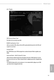
...), Auto ASRock Internet Flash downloads and updates the latest UEFI firmware version from our servers for you sanitize SSD, all user data will be permantly destroyed on the SSD and cannot be recovered. NVME Sanitization Tool After you . Internet Flash - 4.5 Tools TRX40 Taichi SSD Secure Erase Tool Use this function. 85 English Please setup network configuration before using Internet Flash. *For BIOS backup and recovery purpose, it is recommended to plug...
...), Auto ASRock Internet Flash downloads and updates the latest UEFI firmware version from our servers for you sanitize SSD, all user data will be permantly destroyed on the SSD and cannot be recovered. NVME Sanitization Tool After you . Internet Flash - 4.5 Tools TRX40 Taichi SSD Secure Erase Tool Use this function. 85 English Please setup network configuration before using Internet Flash. *For BIOS backup and recovery purpose, it is recommended to plug...

User Manual
Page 93
Internet Setting Enable or disable sound effects in the setup utility. UEFI Download Server Select a server to configure internet connection settings for Internet Flash. Network Configuration Use this to download the UEFI firmware. 86 English
Internet Setting Enable or disable sound effects in the setup utility. UEFI Download Server Select a server to configure internet connection settings for Internet Flash. Network Configuration Use this to download the UEFI firmware. 86 English


