RAID Installation Guide
Page 2
... you to set . Although RAID 0 function can start to use the onboard RAID Option ROM Utility to configure RAID. 1.1 Introduction to RAID The term "RAID" stands for you make a SATA driver diskette, press or to enter BIOS setup to configure RAID functions by using the onboard FastBuild BIOS utility under BIOS environment. AMD BIOS RAID Installation Guide AMD BIOS RAID Installation Guide is a method combining two or more hard disk drives into one drive to the entire system since it does not provide any HDDs of the RAID 0 Disk will cause data...
... you to set . Although RAID 0 function can start to use the onboard RAID Option ROM Utility to configure RAID. 1.1 Introduction to RAID The term "RAID" stands for you make a SATA driver diskette, press or to enter BIOS setup to configure RAID functions by using the onboard FastBuild BIOS utility under BIOS environment. AMD BIOS RAID Installation Guide AMD BIOS RAID Installation Guide is a method combining two or more hard disk drives into one drive to the entire system since it does not provide any HDDs of the RAID 0 Disk will cause data...
RAID Installation Guide
Page 8
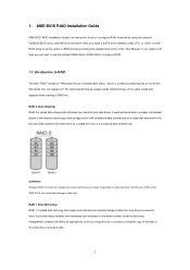
... Support CD into one of the USB port. STEP 3.2: Download driver from ASRock's website and unzip the file into your USB flash drive. 8 STEP 4: Windows installation A. B. STEP 3.1: Copy RAID driver to a USB flash drive You can choose either STEP 3.1 or STEP 3.2 to finish the driver copy process. Plug a USB drive into the DVD-ROM drive. Follow instructions to finish the configuration. Click to Tools Easy RAID Installer F. B. D. E. Go to find the driver inside your USB flash disk. Please download the "SATA Floppy Imaged driver" from ASRock...
... Support CD into one of the USB port. STEP 3.2: Download driver from ASRock's website and unzip the file into your USB flash drive. 8 STEP 4: Windows installation A. B. STEP 3.1: Copy RAID driver to a USB flash drive You can choose either STEP 3.1 or STEP 3.2 to finish the driver copy process. Plug a USB drive into the DVD-ROM drive. Follow instructions to finish the configuration. Click to Tools Easy RAID Installer F. B. D. E. Go to find the driver inside your USB flash disk. Please download the "SATA Floppy Imaged driver" from ASRock...

RAID Installation Guide
Page 12
.... Plug a USB drive into the DVD-ROM drive. D. A. During system boot, press or key to delete the existing disk arrays before creating a new array. Insert the Support CD into one of the USB port. Go to AdvancedRAIDXpert2 Configuration UtilityArray ManagementCreate Array Select Physical DisksCheck AllApply ChangesCreate Array. *Be sure to enter UEFI setup utility. H. Please download the "SATA Floppy Imaged driver...
.... Plug a USB drive into the DVD-ROM drive. D. A. During system boot, press or key to delete the existing disk arrays before creating a new array. Insert the Support CD into one of the USB port. Go to AdvancedRAIDXpert2 Configuration UtilityArray ManagementCreate Array Select Physical DisksCheck AllApply ChangesCreate Array. *Be sure to enter UEFI setup utility. H. Please download the "SATA Floppy Imaged driver...

Quick Installation Guide
Page 6
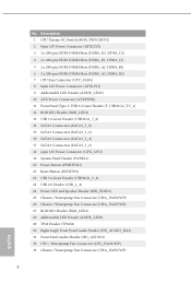
... 6 pin 12V Power Connector (GFX_12V1) 19 System Panel Header (PANEL1) 20 Power Button (PWRBTN1) 21 Reset Button (RSTBTN1) 22 USB 3.2 Gen1 Header (USB32G1_5_6) 23 USB 2.0 Header (USB_1_2) 24 Power LED and Speaker Header (SPK_PLED1) 25 Chassis / Waterpump Fan Connector (CHA_FAN2/WP) 26 Chassis / Waterpump Fan Connector (CHA_FAN3/WP) 27 RGB LED Header (RGB_LED1) 28 Addressable LED Header (ADDR_LED1) 29 TPM Header (TPMS1) 30 Right Angle Front Panel Audio Header (HD_AUDIO_RA1) 31 Front Panel Audio Header (HD_AUDIO1) 32 CPU / Waterpump Fan Connector (CPU_FAN2/WP) 33 Chassis / Waterpump Fan Connector...
... 6 pin 12V Power Connector (GFX_12V1) 19 System Panel Header (PANEL1) 20 Power Button (PWRBTN1) 21 Reset Button (RSTBTN1) 22 USB 3.2 Gen1 Header (USB32G1_5_6) 23 USB 2.0 Header (USB_1_2) 24 Power LED and Speaker Header (SPK_PLED1) 25 Chassis / Waterpump Fan Connector (CHA_FAN2/WP) 26 Chassis / Waterpump Fan Connector (CHA_FAN3/WP) 27 RGB LED Header (RGB_LED1) 28 Addressable LED Header (ADDR_LED1) 29 TPM Header (TPMS1) 30 Right Angle Front Panel Audio Header (HD_AUDIO_RA1) 31 Front Panel Audio Header (HD_AUDIO1) 32 CPU / Waterpump Fan Connector (CPU_FAN2/WP) 33 Chassis / Waterpump Fan Connector...
Quick Installation Guide
Page 7
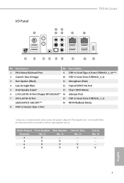
I/O Panel 1 TRX40 Creator 24 35 6 7 16 15 14 13 12 11 10 9 8 No. See the table below for connection details in accordance with the type of speaker you use . Description No. Description 1 PS/2 Mouse/Keyboard Port 9 USB 3.2 Gen2 Type-A Ports (USB32G2_1_2)**** 2 Central / Bass (Orange) 10 USB 3.2 Gen1 Ports (USB32G1_3_4) 3 Rear Speaker (Black) 11 Microphone (Pink) 4 Line In (Light Blue) 12 Optical SPDIF Out Port 5 Front Speaker (Lime)* 13 Clear CMOS Button 6 2.5G LAN RJ...
I/O Panel 1 TRX40 Creator 24 35 6 7 16 15 14 13 12 11 10 9 8 No. See the table below for connection details in accordance with the type of speaker you use . Description No. Description 1 PS/2 Mouse/Keyboard Port 9 USB 3.2 Gen2 Type-A Ports (USB32G2_1_2)**** 2 Central / Bass (Orange) 10 USB 3.2 Gen1 Ports (USB32G1_3_4) 3 Rear Speaker (Black) 11 Microphone (Pink) 4 Line In (Light Blue) 12 Optical SPDIF Out Port 5 Front Speaker (Lime)* 13 Clear CMOS Button 6 2.5G LAN RJ...

Quick Installation Guide
Page 11
... for specific information about the model you for M.2 Sockets (Optional) • 1 x I/O Panel Shield 7 English TRX40 Creator Chapter 1 Introduction Thank you are using. ASRock website http://www.asrock.com. 1.1 Package Contents • ASRock TRX40 Creator Motherboard (ATX Form Factor) • ASRock TRX40 Creator Quick Installation Guide • ASRock TRX40 Creator Support CD • 4 x Serial ATA (SATA) Data Cables (Optional) • 1 x ASRock SLI_HB_Bridge_3S Card (Optional) • 1 x ASRock WiFi 2.4/5 GHz Antenna (Optional) • 3 x Screws for M.2 Sockets (Optional) •...
... for specific information about the model you for M.2 Sockets (Optional) • 1 x I/O Panel Shield 7 English TRX40 Creator Chapter 1 Introduction Thank you are using. ASRock website http://www.asrock.com. 1.1 Package Contents • ASRock TRX40 Creator Motherboard (ATX Form Factor) • ASRock TRX40 Creator Quick Installation Guide • ASRock TRX40 Creator Support CD • 4 x Serial ATA (SATA) Data Cables (Optional) • 1 x ASRock SLI_HB_Bridge_3S Card (Optional) • 1 x ASRock WiFi 2.4/5 GHz Antenna (Optional) • 3 x Screws for M.2 Sockets (Optional) •...
Quick Installation Guide
Page 14
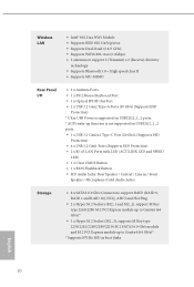
... USB32G2_1_2 ports. • 1 x USB 3.2 Gen2x2 Type-C Port (20 Gb/s) (Supports ESD Protection) • 4 x USB 3.2 Gen1 Ports (Supports ESD Protection) • 2 x RJ-45 LAN Ports with LED (ACT/LINK LED and SPEED LED) • 1 x Clear CMOS Button • 1 x BIOS Flashback Button • HD Audio Jacks: Rear Speaker / Central / Line in / Front Speaker / Microphone (Gold Audio Jacks) Storage • 8 x SATA3 6.0 Gb/s Connectors, support RAID (RAID 0, RAID 1 and RAID 10), NCQ, AHCI and Hot Plug • 2 x Hyper M.2 Sockets (M2_1 and M2_2), support M Key type 2260/2280 M.2 PCI Express module...
... USB32G2_1_2 ports. • 1 x USB 3.2 Gen2x2 Type-C Port (20 Gb/s) (Supports ESD Protection) • 4 x USB 3.2 Gen1 Ports (Supports ESD Protection) • 2 x RJ-45 LAN Ports with LED (ACT/LINK LED and SPEED LED) • 1 x Clear CMOS Button • 1 x BIOS Flashback Button • HD Audio Jacks: Rear Speaker / Central / Line in / Front Speaker / Microphone (Gold Audio Jacks) Storage • 8 x SATA3 6.0 Gb/s Connectors, support RAID (RAID 0, RAID 1 and RAID 10), NCQ, AHCI and Hot Plug • 2 x Hyper M.2 Sockets (M2_1 and M2_2), support M Key type 2260/2280 M.2 PCI Express module...

Quick Installation Guide
Page 30
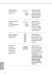
... 1 2 34 This motherboard provides a 4-Pin CPU fan (Quiet Fan) connector. To use a 4-pin ATX power supply, please plug it to Pin 1-3. 12 24 1 13 This motherboard provides a 24-pin ATX power connector. Do not plug the PCIe power cable to connect a 3-Pin CPU fan, please connect it along Pin 1 and Pin 5. *Warning: Please make sure that the power cable connected is for the CPU and not the graphics card. If you plan to Pin 1-3. To 4 1 use a 20-pin ATX power supply, please plug it to connect a 3-Pin CPU water cooler fan, please connect it along Pin 1 and Pin 13...
... 1 2 34 This motherboard provides a 4-Pin CPU fan (Quiet Fan) connector. To use a 4-pin ATX power supply, please plug it to Pin 1-3. 12 24 1 13 This motherboard provides a 24-pin ATX power connector. Do not plug the PCIe power cable to connect a 3-Pin CPU fan, please connect it along Pin 1 and Pin 5. *Warning: Please make sure that the power cable connected is for the CPU and not the graphics card. If you plan to Pin 1-3. To 4 1 use a 20-pin ATX power supply, please plug it to connect a 3-Pin CPU water cooler fan, please connect it along Pin 1 and Pin 13...

Quick Installation Guide
Page 31
... further instructions on this connector when 4 graphics cards are used to connect RGB LED extension cable which can securely store keys, digital certificates, passwords, and data. GN D This connector supports Trusted Platform Module (TPM) system, 1 which allows users to choose from various LED lighting effects. Caution: Never install the RGB LED cable in the wrong orientation; TRX40 Creator Graphics 12V Power Connector (6-pin GFX_12V1) (see p.1, No. 18) TPM Header (17-pin TPMS1) (see p.1, No. 29) RGB LED Headers (4-pin...
... further instructions on this connector when 4 graphics cards are used to connect RGB LED extension cable which can securely store keys, digital certificates, passwords, and data. GN D This connector supports Trusted Platform Module (TPM) system, 1 which allows users to choose from various LED lighting effects. Caution: Never install the RGB LED cable in the wrong orientation; TRX40 Creator Graphics 12V Power Connector (6-pin GFX_12V1) (see p.1, No. 18) TPM Header (17-pin TPMS1) (see p.1, No. 29) RGB LED Headers (4-pin...

Quick Installation Guide
Page 34
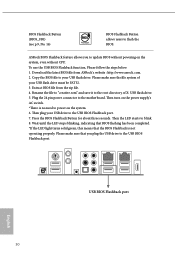
... LED light turns solid green, this means that you to the motherboard. ASRock BIOS Flashback feature allows you plug the USB drive to flash the BIOS. Plug the 24 pin power connector to update BIOS without CPU. Download the latest BIOS file from the zip file. 4. BIOS Flashback Button (BIOS_FB1) (see p.3, No. 16) BIOS Flashback Button allows users to the USB BIOS Flashback port. Extract BIOS file from ASRock's website : http://www.asrock.com. 2. Please make sure the file system of X: USB flash drive. 5. Then turn on the power supply's AC switch...
... LED light turns solid green, this means that you to the motherboard. ASRock BIOS Flashback feature allows you plug the USB drive to flash the BIOS. Plug the 24 pin power connector to update BIOS without CPU. Download the latest BIOS file from the zip file. 4. BIOS Flashback Button (BIOS_FB1) (see p.3, No. 16) BIOS Flashback Button allows users to the USB BIOS Flashback port. Extract BIOS file from ASRock's website : http://www.asrock.com. 2. Please make sure the file system of X: USB flash drive. 5. Then turn on the power supply's AC switch...

User Manual
Page 8
...motherboard, please visit our website for M.2 Sockets (Optional) • 1 x I/O Panel Shield 1 English ASRock website http://www.asrock.com. 1.1 Package Contents • ASRock TRX40 Creator Motherboard (ATX Form Factor) • ASRock TRX40 Creator Quick Installation Guide • ASRock TRX40 Creator Support CD • 4 x Serial ATA (SATA) Data Cables (Optional) • 1 x ASRock SLI_HB_Bridge_3S Card (Optional) • 1 x ASRock WiFi 2.4/5 GHz Antenna (Optional) • 3 x Screws for M.2 Sockets (Optional) • 3 x Standoffs for specific information about the model you are using...
...motherboard, please visit our website for M.2 Sockets (Optional) • 1 x I/O Panel Shield 1 English ASRock website http://www.asrock.com. 1.1 Package Contents • ASRock TRX40 Creator Motherboard (ATX Form Factor) • ASRock TRX40 Creator Quick Installation Guide • ASRock TRX40 Creator Support CD • 4 x Serial ATA (SATA) Data Cables (Optional) • 1 x ASRock SLI_HB_Bridge_3S Card (Optional) • 1 x ASRock WiFi 2.4/5 GHz Antenna (Optional) • 3 x Screws for M.2 Sockets (Optional) • 3 x Standoffs for specific information about the model you are using...
User Manual
Page 15
... 6 pin 12V Power Connector (GFX_12V1) 19 System Panel Header (PANEL1) 20 Power Button (PWRBTN1) 21 Reset Button (RSTBTN1) 22 USB 3.2 Gen1 Header (USB32G1_5_6) 23 USB 2.0 Header (USB_1_2) 24 Power LED and Speaker Header (SPK_PLED1) 25 Chassis / Waterpump Fan Connector (CHA_FAN2/WP) 26 Chassis / Waterpump Fan Connector (CHA_FAN3/WP) 27 RGB LED Header (RGB_LED1) 28 Addressable LED Header (ADDR_LED1) 29 TPM Header (TPMS1) 30 Right Angle Front Panel Audio Header (HD_AUDIO_RA1) 31 Front Panel Audio Header (HD_AUDIO1) 32 CPU / Waterpump Fan Connector (CPU_FAN2/WP) 33 Chassis / Waterpump Fan Connector...
... 6 pin 12V Power Connector (GFX_12V1) 19 System Panel Header (PANEL1) 20 Power Button (PWRBTN1) 21 Reset Button (RSTBTN1) 22 USB 3.2 Gen1 Header (USB32G1_5_6) 23 USB 2.0 Header (USB_1_2) 24 Power LED and Speaker Header (SPK_PLED1) 25 Chassis / Waterpump Fan Connector (CHA_FAN2/WP) 26 Chassis / Waterpump Fan Connector (CHA_FAN3/WP) 27 RGB LED Header (RGB_LED1) 28 Addressable LED Header (ADDR_LED1) 29 TPM Header (TPMS1) 30 Right Angle Front Panel Audio Header (HD_AUDIO_RA1) 31 Front Panel Audio Header (HD_AUDIO1) 32 CPU / Waterpump Fan Connector (CPU_FAN2/WP) 33 Chassis / Waterpump Fan Connector...
User Manual
Page 33
... connect a 3-Pin CPU water cooler fan, please connect it along Pin 1 and Pin 13. 8 5 This motherboard provides two 8-pin ATX 12V power connectors. Do not plug the PCIe power cable to Pin 1-3. If you plan to connect a 3-Pin CPU fan, please connect it along Pin 1 and Pin 5. *Warning: Please make sure that the power cable connected is for the CPU and not the graphics card. To use a 4-pin ATX power supply, please plug it to Pin 1-3. 12 24 1 13 This motherboard provides a 24-pin ATX power connector. English 26 CPU Fan Connector (4-pin CPU_FAN1) (see p.7, No. 7) CPU...
... connect a 3-Pin CPU water cooler fan, please connect it along Pin 1 and Pin 13. 8 5 This motherboard provides two 8-pin ATX 12V power connectors. Do not plug the PCIe power cable to Pin 1-3. If you plan to connect a 3-Pin CPU fan, please connect it along Pin 1 and Pin 5. *Warning: Please make sure that the power cable connected is for the CPU and not the graphics card. To use a 4-pin ATX power supply, please plug it to Pin 1-3. 12 24 1 13 This motherboard provides a 24-pin ATX power connector. English 26 CPU Fan Connector (4-pin CPU_FAN1) (see p.7, No. 7) CPU...
User Manual
Page 37
... to update BIOS without powering on the system. 6. Press the BIOS Flashback Button for about three seconds. Download the latest BIOS file from the zip file. 4. Plug the 24 pin power connector to your USB flash drive. Then turn on the power supply's AC switch. *There is not operating properly. Please make sure the file system of X: USB flash drive. 5. Extract BIOS file from ASRock's website : http://www.asrock.com. 2. Wait until the LED stops blinking, indicating that BIOS flashing has...
... to update BIOS without powering on the system. 6. Press the BIOS Flashback Button for about three seconds. Download the latest BIOS file from the zip file. 4. Plug the 24 pin power connector to your USB flash drive. Then turn on the power supply's AC switch. *There is not operating properly. Please make sure the file system of X: USB flash drive. 5. Extract BIOS file from ASRock's website : http://www.asrock.com. 2. Wait until the LED stops blinking, indicating that BIOS flashing has...

User Manual
Page 51
... mode. 5. 2.9 CrossFireXTM, 3-Way CrossFireXTM and 4-Way CrossFireXTM Operation Guide This motherboard supports CrossFireXTM, 3-way CrossFireXTM and 4-way CrossFireXTM that your graphics card driver supports AMD CrossFireXTM technology. You should only use identical CrossFireXTM-ready graphics cards that the cards are AMD certified. 2. Make sure that are properly seated on the top of the graphics cards. (The CrossFire Bridge is recommended to enable CrossFireXTM. CrossFire Bridge Step 2 Connect two graphics cards by installing...
... mode. 5. 2.9 CrossFireXTM, 3-Way CrossFireXTM and 4-Way CrossFireXTM Operation Guide This motherboard supports CrossFireXTM, 3-way CrossFireXTM and 4-way CrossFireXTM that your graphics card driver supports AMD CrossFireXTM technology. You should only use identical CrossFireXTM-ready graphics cards that the cards are AMD certified. 2. Make sure that are properly seated on the top of the graphics cards. (The CrossFire Bridge is recommended to enable CrossFireXTM. CrossFire Bridge Step 2 Connect two graphics cards by installing...

User Manual
Page 54
... Uninstaller is an optional download. AMD Catalyst Control Center Step 4 Double-click the AMD Catalyst Control Center icon in your graphics card and click Apply. Step 5 In the left pane, click Performance and then AMD CrossFireXTM. English 47 Step 3 Install the required drivers and CATALYST Control Center then restart your computer and boot into OS. Please check AMD's website for AMD driver updates. TRX40 Creator 2.9.4 Driver Installation and Setup Step 1 Power on your...
... Uninstaller is an optional download. AMD Catalyst Control Center Step 4 Double-click the AMD Catalyst Control Center icon in your graphics card and click Apply. Step 5 In the left pane, click Performance and then AMD CrossFireXTM. English 47 Step 3 Install the required drivers and CATALYST Control Center then restart your computer and boot into OS. Please check AMD's website for AMD driver updates. TRX40 Creator 2.9.4 Driver Installation and Setup Step 1 Power on your...

User Manual
Page 61
... 3.1 Installing Drivers The Support CD that comes with the motherboard contains necessary drivers and useful utilities that the motherboard supports. If the Main Menu does not appear automatically, locate and double click on the support CD driver page. Therefore, the drivers you install can work properly. Please click Install All or follow the installation wizard to your system will be auto-detected and listed on the file "ASRSETUP.EXE" in your CD-ROM drive.
... 3.1 Installing Drivers The Support CD that comes with the motherboard contains necessary drivers and useful utilities that the motherboard supports. If the Main Menu does not appear automatically, locate and double click on the support CD driver page. Therefore, the drivers you install can work properly. Please click Install All or follow the installation wizard to your system will be auto-detected and listed on the file "ASRSETUP.EXE" in your CD-ROM drive.
User Manual
Page 78
.... DRAM Frequency If [Auto] is selected, the motherboard will be enabled to support memory and Infinity Fabric overclocking. Infinity Fabric Frequency and Dividers Set Infinity Fabric Frequency and Dividers (FCLK). Final result is depending on processors with integrated graphics. CLDO VDDG Voltage Control VDDG represents voltage for the DDR4 bus signaling (PHY), and it is dereived from your DRAM voltage. TRX40 Creator CPU Frequency and Voltage (VID) Change If this item is set based on user selection...
.... DRAM Frequency If [Auto] is selected, the motherboard will be enabled to support memory and Infinity Fabric overclocking. Infinity Fabric Frequency and Dividers Set Infinity Fabric Frequency and Dividers (FCLK). Final result is depending on processors with integrated graphics. CLDO VDDG Voltage Control VDDG represents voltage for the DDR4 bus signaling (PHY), and it is dereived from your DRAM voltage. TRX40 Creator CPU Frequency and Voltage (VID) Change If this item is set based on user selection...

User Manual
Page 91
... USB storage device and run Instant Flash to securely erase SSD. Internet Flash - DHCP (Auto IP), Auto ASRock Internet Flash downloads and updates the latest UEFI firmware version from our servers for you sanitize SSD, all user data will be permantly destroyed on the SSD and cannot be recovered. NVME Sanitization Tool After you . Please setup network configuration before using Internet Flash. *For BIOS backup and recovery purpose, it is recommended to plug...
... USB storage device and run Instant Flash to securely erase SSD. Internet Flash - DHCP (Auto IP), Auto ASRock Internet Flash downloads and updates the latest UEFI firmware version from our servers for you sanitize SSD, all user data will be permantly destroyed on the SSD and cannot be recovered. NVME Sanitization Tool After you . Please setup network configuration before using Internet Flash. *For BIOS backup and recovery purpose, it is recommended to plug...
User Manual
Page 92
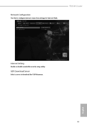
TRX40 Creator Internet Setting Enable or disable sound effects in the setup utility. UEFI Download Server Select a server to configure internet connection settings for Internet Flash. English 85 Network Configuration Use this to download the UEFI firmware.
TRX40 Creator Internet Setting Enable or disable sound effects in the setup utility. UEFI Download Server Select a server to configure internet connection settings for Internet Flash. English 85 Network Configuration Use this to download the UEFI firmware.


