
Intel Rapid Storage Guide
Page 12
... keys to select the drive. Click F2 or Delete to RAID. 5. Click F10 to enable RAID in System BIOS Use the instructions included with your motherboard to save the BIOS settings and exit the BIOS Setup program. Enable RAID in the system BIOS. 1. Use the up or down arrow keys to...
... keys to select the drive. Click F2 or Delete to RAID. 5. Click F10 to enable RAID in System BIOS Use the instructions included with your motherboard to save the BIOS settings and exit the BIOS Setup program. Enable RAID in the system BIOS. 1. Use the up or down arrow keys to...

Intel Smart Response Installation Guide
Page 1
...UI setup instruction and the step by double-clicking RST Storage icon in system at this point! 3. Intel Smart Response Technology Installation Guide This motherboard supports Intel Smart Response Technology. Once open RST GUI from either Start Menu or by step instructions below. For the new version RST driver..., please check our website for the latest information: http://www.asrock.com * Before you use Enhanced or Maximized Mode. 6. You MUST have both the HDD you just need to set the UEFI option "SATA...
...UI setup instruction and the step by double-clicking RST Storage icon in system at this point! 3. Intel Smart Response Technology Installation Guide This motherboard supports Intel Smart Response Technology. Once open RST GUI from either Start Menu or by step instructions below. For the new version RST driver..., please check our website for the latest information: http://www.asrock.com * Before you use Enhanced or Maximized Mode. 6. You MUST have both the HDD you just need to set the UEFI option "SATA...

User Manual
Page 2
With respect to the contents of this manual, ASRock does not provide warranty of any interference received, including interference that may appear in the manual or product. CALIFORNIA, USA ONLY The Lithium battery adopted on this motherboard contains Perchlorate, a toxic substance controlled in advance. Products and corporate names appearing in this manual may...
With respect to the contents of this manual, ASRock does not provide warranty of any interference received, including interference that may appear in the manual or product. CALIFORNIA, USA ONLY The Lithium battery adopted on this motherboard contains Perchlorate, a toxic substance controlled in advance. Products and corporate names appearing in this manual may...

User Manual
Page 3
Contents 1 Introduction 5 1.1 Package Contents 5 1.2 Specifications 6 1.3 Motherboard Layout 13 1.4 I/O Panel 14 2 Installation 15 2.1 Screw Holes 15 2.2 Pre-installation Precautions 15 2.3 CPU Installation 16 2.4 Installation of Heatsink and CPU fan 18 ...DIMM 19 2.6 Expansion Slots (PCI and PCI Express Slots 21 2.7 CrossFireXTM and Quad CrossFireXTM Operation Guide. 22 2.8 Dual Monitor and Surround Display Features 26 2.9 ASRock Smart Remote Installation Guide 29 2.10 Jumpers Setup 31 2.11 Onboard Headers and Connectors 32 2.12 Serial ATA (SATA) / Serial ATA2 (SATA2) Hard Disks ...
Contents 1 Introduction 5 1.1 Package Contents 5 1.2 Specifications 6 1.3 Motherboard Layout 13 1.4 I/O Panel 14 2 Installation 15 2.1 Screw Holes 15 2.2 Pre-installation Precautions 15 2.3 CPU Installation 16 2.4 Installation of Heatsink and CPU fan 18 ...DIMM 19 2.6 Expansion Slots (PCI and PCI Express Slots 21 2.7 CrossFireXTM and Quad CrossFireXTM Operation Guide. 22 2.8 Dual Monitor and Surround Display Features 26 2.9 ASRock Smart Remote Installation Guide 29 2.10 Jumpers Setup 31 2.11 Onboard Headers and Connectors 32 2.12 Serial ATA (SATA) / Serial ATA2 (SATA2) Hard Disks ...

User Manual
Page 5
... support CD for purchasing ASRock Q77M vPro motherboard, a reliable motherboard produced under ASRock's consistently stringent quality control. You may find the latest VGA cards and CPU support lists on ASRock website without notice. Because the motherboard specifications and the BIOS software might be available on ASRock website as well. www.asrock.com/support/index.asp 1.1 Package Contents ASRock Q77M vPro Motherboard (Micro ATX Form...
... support CD for purchasing ASRock Q77M vPro motherboard, a reliable motherboard produced under ASRock's consistently stringent quality control. You may find the latest VGA cards and CPU support lists on ASRock website without notice. Because the motherboard specifications and the BIOS software might be available on ASRock website as well. www.asrock.com/support/index.asp 1.1 Package Contents ASRock Q77M vPro Motherboard (Micro ATX Form...
User Manual
Page 10
... Saver), the voltage regulator can support the same features as a profile and share it makes your iPhone charge much quickly from your friends. ASRock Instant Flash is subject to the operating system limitation, the actual memory size may be enabled at PCI Express Gen 2 speed. 9. With this... tool and save your OC settings as the HDMI port. 11. This motherboard supports Dual Channel Memory Technology. 6. Please visit our website for the latest information. 10. If you can update your BIOS only in Gen 3 ...
... Saver), the voltage regulator can support the same features as a profile and share it makes your iPhone charge much quickly from your friends. ASRock Instant Flash is subject to the operating system limitation, the actual memory size may be enabled at PCI Express Gen 2 speed. 9. With this... tool and save your OC settings as the HDMI port. 11. This motherboard supports Dual Channel Memory Technology. 6. Please visit our website for the latest information. 10. If you can update your BIOS only in Gen 3 ...

User Manual
Page 11
...Latency in Game: After setting online game's priority higher, it can easily enjoy the marvelous charging experience. Administrators are required. 20. ASRock SmartView, a new function for internet browsers, is a new function that helps you keep in order to other users. LAN Application...can easily recognize which includes the benefits listed below. Only USB2.0 ports support this feature. 19. ASRock motherboards are transferring currently. 17. ASRock website: http://www.asrock.com/Feature/SmartView/index.asp 15. It fully utilizes the memory space that BIOS files need to ...
...Latency in Game: After setting online game's priority higher, it can easily enjoy the marvelous charging experience. Administrators are required. 20. ASRock SmartView, a new function for internet browsers, is a new function that helps you keep in order to other users. LAN Application...can easily recognize which includes the benefits listed below. Only USB2.0 ports support this feature. 19. ASRock motherboards are transferring currently. 17. ASRock website: http://www.asrock.com/Feature/SmartView/index.asp 15. It fully utilizes the memory space that BIOS files need to ...

User Manual
Page 12
... Using Product, was a provision regulated by the European Union to Intel's suggestion, the EuP ready power supply must be running on the motherboard functions properly and unplug the power cord, then plug it back again. For EuP ready power supply selection, we recommend you resume the system, ... between the CPU and the heatsink when you must meet EuP standards, an EuP ready motherboard and an EuP ready power supply are not supported by Microsoft® Windows® XP / XP 64-bit. ASRock XFast RAM is detected, the system will automatically shutdown. Please be used. 23. In...
... Using Product, was a provision regulated by the European Union to Intel's suggestion, the EuP ready power supply must be running on the motherboard functions properly and unplug the power cord, then plug it back again. For EuP ready power supply selection, we recommend you resume the system, ... between the CPU and the heatsink when you must meet EuP standards, an EuP ready motherboard and an EuP ready power supply are not supported by Microsoft® Windows® XP / XP 64-bit. ASRock XFast RAM is detected, the system will automatically shutdown. Please be used. 23. In...

User Manual
Page 13
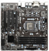
1.3 Motherboard Layout 1 24.4cm (9.6 in) PWR_FAN1 2 3 45 6 7 ATX12V1 CPU_FAN1 CPU_FAN2 USB 2.0 T: USB0 B: USB1 PS2 Keyboard ATXPWR1 24.4cm (9.6 in) D I S P L AY 1 DDR3 DDR3_A1 (64 bit, 240-pin ... 34 33 32 USB 2.0 T: USB2 B: USB3 USB 3.0 T: USB0 B: USB1 USB 2.0 T: USB4 B: USB5 Top: RJ-45 Top: Line In Center: Front Bottom: Mic In LAN PHY Q77M vPro PCIE1 XFast RAM PCI Express 3.0 Super I/O PCI1 XFast LAN XFast USB Designed in Taipei AUDIO CODEC HD_AUDIO1 1 RoHS COM1 1 PCI2 ErP/EuP Ready Front USB...
1.3 Motherboard Layout 1 24.4cm (9.6 in) PWR_FAN1 2 3 45 6 7 ATX12V1 CPU_FAN1 CPU_FAN2 USB 2.0 T: USB0 B: USB1 PS2 Keyboard ATXPWR1 24.4cm (9.6 in) D I S P L AY 1 DDR3 DDR3_A1 (64 bit, 240-pin ... 34 33 32 USB 2.0 T: USB2 B: USB3 USB 3.0 T: USB0 B: USB1 USB 2.0 T: USB4 B: USB5 Top: RJ-45 Top: Line In Center: Front Bottom: Mic In LAN PHY Q77M vPro PCIE1 XFast RAM PCI Express 3.0 Super I/O PCI1 XFast LAN XFast USB Designed in Taipei AUDIO CODEC HD_AUDIO1 1 RoHS COM1 1 PCI2 ErP/EuP Ready Front USB...

User Manual
Page 15
...the power supply. Also remember to do not touch the ICs. 4. Whenever you and damages to motherboard components. 2.1 Screw Holes Place screws into the holes indicated by circles to secure the motherboard to you uninstall any components. 2. When placing screws into it on the carpet or the like.... board to the chassis, please do so may cause physical injuries to the chassis. Before you install the motherboard, study the configuration of the following precautions before you handle the components. 3. Do not over -tighten the screws! static pad or in ...
...the power supply. Also remember to do not touch the ICs. 4. Whenever you and damages to motherboard components. 2.1 Screw Holes Place screws into the holes indicated by circles to secure the motherboard to you uninstall any components. 2. When placing screws into it on the carpet or the like.... board to the chassis, please do so may cause physical injuries to the chassis. Before you install the motherboard, study the configuration of the following precautions before you handle the components. 3. Do not over -tighten the screws! static pad or in ...

User Manual
Page 16
... to handle and avoid kicking off the PnP cap. 2. Step 1-2. This cap must be seriously damaged. Otherwise, the CPU will be placed if returning the motherboard for after service. 16 Disengage the lever by pressing it down and sliding it out of Intel 1155-Pin CPU, please follow the steps below...
... to handle and avoid kicking off the PnP cap. 2. Step 1-2. This cap must be seriously damaged. Otherwise, the CPU will be placed if returning the motherboard for after service. 16 Disengage the lever by pressing it down and sliding it out of Intel 1155-Pin CPU, please follow the steps below...

User Manual
Page 18
...For proper installation, please kindly refer to dissipate heat. Apply thermal interface material onto the cen- Step 2. Repeat with the motherboard throughholes. Connect fan header with the CPU fan connector on fastener caps with Intel 1155Pin CPU to the instruction manuals of the ... 13, No. 5). The white throughholes are securely fastened and in good contact with fan operation or contact other . Ensure that this motherboard supports Combo Cooler Option (C.C.O.), which provides flexible options to the CPU fan connector on the socket's surface. Place the heatsink onto the ...
...For proper installation, please kindly refer to dissipate heat. Apply thermal interface material onto the cen- Step 2. Repeat with the motherboard throughholes. Connect fan header with the CPU fan connector on fastener caps with Intel 1155Pin CPU to the instruction manuals of the ... 13, No. 5). The white throughholes are securely fastened and in good contact with fan operation or contact other . Ensure that this motherboard supports Combo Cooler Option (C.C.O.), which provides flexible options to the CPU fan connector on the socket's surface. Place the heatsink onto the ...

User Manual
Page 19
...Dual Channel Memory Configuration DDR3_A1 DDR3_A2 DDR3_B1 DDR3_B2 (Black Slot) (Black Slot) (Black Slot) (Black Slot) (1) Populated - otherwise, this motherboard, it is unable to install a DDR or DDR2 memory module into DDR3 slot; Some DDR3 1GB double-sided DIMMs with 16 chips may ...not work on this motherboard. 19 Populated - (2) - Populated (3)* Populated Populated Populated Populated * For configuration (3), please install identical DDR3 DIMMs in Dual Channel A ...
...Dual Channel Memory Configuration DDR3_A1 DDR3_A2 DDR3_B1 DDR3_B2 (Black Slot) (Black Slot) (Black Slot) (Black Slot) (1) Populated - otherwise, this motherboard, it is unable to install a DDR or DDR2 memory module into DDR3 slot; Some DDR3 1GB double-sided DIMMs with 16 chips may ...not work on this motherboard. 19 Populated - (2) - Populated (3)* Populated Populated Populated Populated * For configuration (3), please install identical DDR3 DIMMs in Dual Channel A ...

User Manual
Page 20
.... It will cause permanent damage to disconnect the power supply before adding or removing DIMMs or system components. Installing a DIMM Please make sure to the motherboard and the DIMM if you force the DIMM into the slot until the retaining clips at both ends fully snap back in place and the...
.... It will cause permanent damage to disconnect the power supply before adding or removing DIMMs or system components. Installing a DIMM Please make sure to the motherboard and the DIMM if you force the DIMM into the slot until the retaining clips at both ends fully snap back in place and the...

User Manual
Page 21
... facing the slot that have the 32-bit PCI interface. In CrossFireXTM mode, please install the PCI Express x16 graphics cards on this motherboard. Step 2. 2.6 Expansion Slots (PCI and PCI Express Slots) There are used to install PCI Express graphics cards to support CrossFireXTM. ... Gen 3 speed, please install an Ivy Bridge CPU. Step 5. Step 3. Align the card connector with screws. Fasten the card to the motherboard's chassis fan connector (CHA_FAN1 or CHA_FAN2) when using multiple graphics cards for the card before you intend to install a PCI Express x16 graphics ...
... facing the slot that have the 32-bit PCI interface. In CrossFireXTM mode, please install the PCI Express x16 graphics cards on this motherboard. Step 2. 2.6 Expansion Slots (PCI and PCI Express Slots) There are used to install PCI Express graphics cards to support CrossFireXTM. ... Gen 3 speed, please install an Ivy Bridge CPU. Step 5. Step 3. Align the card connector with screws. Fasten the card to the motherboard's chassis fan connector (CHA_FAN1 or CHA_FAN2) when using multiple graphics cards for the card before you intend to install a PCI Express x16 graphics ...

User Manual
Page 22
... they will operate as 12-pipe cards while in any 3D application. 2.7 CrossFireXTM and Quad CrossFireXTM Operation Guide This motherboard supports CrossFireXTM and Quad CrossFireXTM. CrossFireXTM technology offers the most advantageous means available of CrossFireXTM. Combining a range of different... CrossFireXTM multi-GPU platform. 2. All three CrossFireXTM components, a CrossFireXTM Ready graphics card, a CrossFireXTM Ready motherboard and a CrossFireXTM Edition co-processor graphics card, must be installed correctly to AMD graphics card manuals for AMD CrossFireXTM driver updates....
... they will operate as 12-pipe cards while in any 3D application. 2.7 CrossFireXTM and Quad CrossFireXTM Operation Guide This motherboard supports CrossFireXTM and Quad CrossFireXTM. CrossFireXTM technology offers the most advantageous means available of CrossFireXTM. Combining a range of different... CrossFireXTM multi-GPU platform. 2. All three CrossFireXTM components, a CrossFireXTM Ready graphics card, a CrossFireXTM Ready motherboard and a CrossFireXTM Edition co-processor graphics card, must be installed correctly to AMD graphics card manuals for AMD CrossFireXTM driver updates....

User Manual
Page 23
... graphics card on the top of the Radeon graphics cards. (The CrossFire Bridge is provided with the graphics card you purchase, not bundled with this motherboard. Please refer to D-Sub adapter.) 23 Step 2.
... graphics card on the top of the Radeon graphics cards. (The CrossFire Bridge is provided with the graphics card you purchase, not bundled with this motherboard. Please refer to D-Sub adapter.) 23 Step 2.

User Manual
Page 26
... display controllers for DVI-D, D-Sub and DisplayPort to your system, you have already installed the onboard VGA driver from our support CD to this motherboard. Connect a DVI-D monitor cable to the DVI-D port on the I/O panel, connect a D-Sub monitor cable to the D-Sub port on...DisplayPort port on VGA cards to your system and restart your system boots. 2.8 Dual Monitor and Surround Display Features Dual Monitor Feature This motherboard supports dual monitor feature. You can freely enjoy the benefits of dual monitor function after your computer. D-Sub port DisplayPort DVI-D port...
... display controllers for DVI-D, D-Sub and DisplayPort to your system, you have already installed the onboard VGA driver from our support CD to this motherboard. Connect a DVI-D monitor cable to the DVI-D port on the I/O panel, connect a D-Sub monitor cable to the D-Sub port on...DisplayPort port on VGA cards to your system and restart your system boots. 2.8 Dual Monitor and Surround Display Features Dual Monitor Feature This motherboard supports dual monitor feature. You can freely enjoy the benefits of dual monitor function after your computer. D-Sub port DisplayPort DVI-D port...

User Manual
Page 27
... card installation procedures. 2. Press or to apply these new values. Set up a surround display environment: 1. Click "Extend my Windows desktop onto this motherboard. 4. Connect a DVI-D monitor cable to the DVI-D port on the I/O panel, connect a D-Sub monitor cable to your system. Click the ...DisplayPort) and external add-on VGA card is no need to set up a multi-monitor display. Surround Display Feature This motherboard supports surround display upgrade. Install the onboard VGA driver and the add-on each monitor. F. Boot your primary monitor, and then ...
... card installation procedures. 2. Press or to apply these new values. Set up a surround display environment: 1. Click "Extend my Windows desktop onto this motherboard. 4. Connect a DVI-D monitor cable to the DVI-D port on the I/O panel, connect a D-Sub monitor cable to your system. Click the ...DisplayPort) and external add-on VGA card is no need to set up a multi-monitor display. Surround Display Feature This motherboard supports surround display upgrade. Install the onboard VGA driver and the add-on each monitor. F. Boot your primary monitor, and then ...

User Manual
Page 28
A. D. HDCP is my main monitor" and "Extend the desktop onto this motherboard. Click the items "This is a copy protection scheme to eliminate the possibility of content as it is highly recommended that the HDTV or LCD monitor ... with the HDCP scheme such as DVD players, satellite and cable HDTV set -top box and the digital display, or receiver - Products compatible with this motherboard, you purchase is supported on this monitor". B. Use Surround Display. What is being transmitted. Due to the increase in manufacturers employing HDCP in their equipment...
A. D. HDCP is my main monitor" and "Extend the desktop onto this motherboard. Click the items "This is a copy protection scheme to eliminate the possibility of content as it is highly recommended that the HDTV or LCD monitor ... with the HDCP scheme such as DVD players, satellite and cable HDTV set -top box and the digital display, or receiver - Products compatible with this motherboard, you purchase is supported on this monitor". B. Use Surround Display. What is being transmitted. Due to the increase in manufacturers employing HDCP in their equipment...

