User Manual
Page 3
... Setup Guide 18 2.8 Serial ATA (SATA) / Serial ATAII (SATAII) Hard Disks Installation 19 2.9 Driver Installation Guide 20 2.10 Untied Overclocking Technology 20 3 BIOS SETUP UTILITY 21 3.1 Introduction 21 3.1.1 BIOS Menu Bar 21 3.1.2 Navigation Keys 22 3.2 Main Screen 22 3.3 OC Tweaker Screen 23 3.4 Advanced Screen 26 3.4.1 CPU Configuration 27 3.4.2 Chipset Configuration 28 3.4.3 ACPI...
... Setup Guide 18 2.8 Serial ATA (SATA) / Serial ATAII (SATAII) Hard Disks Installation 19 2.9 Driver Installation Guide 20 2.10 Untied Overclocking Technology 20 3 BIOS SETUP UTILITY 21 3.1 Introduction 21 3.1.1 BIOS Menu Bar 21 3.1.2 Navigation Keys 22 3.2 Main Screen 22 3.3 OC Tweaker Screen 23 3.4 Advanced Screen 26 3.4.1 CPU Configuration 27 3.4.2 Chipset Configuration 28 3.4.3 ACPI...

User Manual
Page 5
... be updated, the content of this motherboard, please visit our website for purchasing ASRock PV530 motherboard, a reliable motherboard produced under ASRock's consistently stringent quality control. ASRock website http://www.asrock.com If you are using. Chapter 3 and 4 contain the configuration guide to BIOS setup and information of the motherboard and step-by-step guide to this...
... be updated, the content of this motherboard, please visit our website for purchasing ASRock PV530 motherboard, a reliable motherboard produced under ASRock's consistently stringent quality control. ASRock website http://www.asrock.com If you are using. Chapter 3 and 4 contain the configuration guide to BIOS setup and information of the motherboard and step-by-step guide to this...

User Manual
Page 7
...For detailed product information, please visit our website: http://www.asrock.com WARNING Please realize that there is a certain risk involved with overclocking, including adjusting the setting in the BIOS, applying Untied Overclocking Technology, or using the thirdparty overclocking ...7 OEM and Trial; Hybrid Booster: - Microsoft® Windows® 7 / VistaTM / XP compliant Certifications - ASRock Instant Flash (see CAUTION 8) - BIOS Feature - 4Mb AMI BIOS - Creative Sound Blaster X-Fi MB - CPU/Chassis/Power Fan Tachometer - Voltage Monitoring: +12V, +5V, +3.3V,...
...For detailed product information, please visit our website: http://www.asrock.com WARNING Please realize that there is a certain risk involved with overclocking, including adjusting the setting in the BIOS, applying Untied Overclocking Technology, or using the thirdparty overclocking ...7 OEM and Trial; Hybrid Booster: - Microsoft® Windows® 7 / VistaTM / XP compliant Certifications - ASRock Instant Flash (see CAUTION 8) - BIOS Feature - 4Mb AMI BIOS - Creative Sound Blaster X-Fi MB - CPU/Chassis/Power Fan Tachometer - Voltage Monitoring: +12V, +5V, +3.3V,...

User Manual
Page 8
...be shared and worked on page 18 to SATAII connector directly. 5. It is capable of the system or damage the CPU. 9. This convenient BIOS update tool allows you to access ASRock Instant Flash. With this tool and save your OC settings as yours! Before you what it is a user-friendly... ASRock overclocking tool which allows you to update system BIOS without preparing an additional floppy diskette or other than the recommended CPU bus frequencies may be noted that the OC ...
...be shared and worked on page 18 to SATAII connector directly. 5. It is capable of the system or damage the CPU. 9. This convenient BIOS update tool allows you to access ASRock Instant Flash. With this tool and save your OC settings as yours! Before you what it is a user-friendly... ASRock overclocking tool which allows you to update system BIOS without preparing an additional floppy diskette or other than the recommended CPU bus frequencies may be noted that the OC ...

User Manual
Page 10
Blue) 9 USB 2.0 Header (USB4_5, Blue) 21 VIA VX900 Chipset 10 BIOS SPI Chip 22 USB_PWR2 Jumper 11 Chassis Fan Connector (CHA_FAN1) 23 CPU Fan Connector (CPU_FAN1) 12 System Panel Header (PANEL1, White) 10 Blue) 19 ... HD_AUDIO1 1 SATAII_2 SATAII_1 PCIE1 AUDIO CODEC Super IO PCI1 Designed in Taipei 1 USB6_7 1 USB4_5 1 USB_PWR3 CLRCMOS1 CMOS Battery 4Mb BIOS PANEL 1 PLED PWRBTN SPEAKER1 1 1 HDLED RESET CHA_FAN1 15 14 13 12 11 RoHS PV530 8 9 10 1 Power Fan Connector (PWR_FAN1) 13 Chassis Speaker Header (SPEAKER 1, White) 2 PS2_USB_PWR1 Jumper 14 Clear CMOS Jumper (...
Blue) 9 USB 2.0 Header (USB4_5, Blue) 21 VIA VX900 Chipset 10 BIOS SPI Chip 22 USB_PWR2 Jumper 11 Chassis Fan Connector (CHA_FAN1) 23 CPU Fan Connector (CPU_FAN1) 12 System Panel Header (PANEL1, White) 10 Blue) 19 ... HD_AUDIO1 1 SATAII_2 SATAII_1 PCIE1 AUDIO CODEC Super IO PCI1 Designed in Taipei 1 USB6_7 1 USB4_5 1 USB_PWR3 CLRCMOS1 CMOS Battery 4Mb BIOS PANEL 1 PLED PWRBTN SPEAKER1 1 1 HDLED RESET CHA_FAN1 15 14 13 12 11 RoHS PV530 8 9 10 1 Power Fan Connector (PWR_FAN1) 13 Chassis Speaker Header (SPEAKER 1, White) 2 PS2_USB_PWR1 Jumper 14 Clear CMOS Jumper (...

User Manual
Page 15
... in CMOS. After waiting for 15 seconds, use a jumper cap to enable (see p.10, No. 14) Default Clear CMOS Note: CLRCMOS1 allows you update the BIOS. When the jumper cap is placed on pins, the jumper is "Short". Clear CMOS Jumper 1_2 2_3 (CLRCMOS1) (see p.10, No. 2) +5V +5VSB +5VSB (standby...setup information such as system password, date, time, and system setup parameters. If you need to clear the CMOS when you just finish updating the BIOS, you do not clear the CMOS right after you to default setup, please turn off the computer and unplug the power cord from the power...
... in CMOS. After waiting for 15 seconds, use a jumper cap to enable (see p.10, No. 14) Default Clear CMOS Note: CLRCMOS1 allows you update the BIOS. When the jumper cap is placed on pins, the jumper is "Short". Clear CMOS Jumper 1_2 2_3 (CLRCMOS1) (see p.10, No. 2) +5V +5VSB +5VSB (standby...setup information such as system password, date, time, and system setup parameters. If you need to clear the CMOS when you just finish updating the BIOS, you do not clear the CMOS right after you to default setup, please turn off the computer and unplug the power cord from the power...

User Manual
Page 20
... compatible to [CPU, PCIE, Async.]. Please refer to fixed PCI bus. Therefore, the drivers you enable Untied Overclocking function, please enter "Overclock Mode" option of BIOS setup to set the selection from up to bottom side to your system can be auto-detected and listed on page 7 for the possible overclocking...
... compatible to [CPU, PCIE, Async.]. Please refer to fixed PCI bus. Therefore, the drivers you enable Untied Overclocking function, please enter "Overclock Mode" option of BIOS setup to set the selection from up to bottom side to your system can be auto-detected and listed on page 7 for the possible overclocking...

User Manual
Page 21
...Security To set up the security features Chipset To set up the computer. Please press during the Power-On-Self-Test (POST) to enter the BIOS SETUP UTILITY, otherwise, POST will continue with the following selections: Main To set up the system time/date information OC Tweaker To set up ...overclocking features Advanced To set up the advanced BIOS features H/W Monitor To display current hardware status Boot To set up the default system device to get into the sub screen. 21 Because the...
...Security To set up the security features Chipset To set up the computer. Please press during the Power-On-Self-Test (POST) to enter the BIOS SETUP UTILITY, otherwise, POST will continue with the following selections: Main To set up the system time/date information OC Tweaker To set up ...overclocking features Advanced To set up the advanced BIOS features H/W Monitor To display current hardware status Boot To set up the default system device to get into the sub screen. 21 Because the...

User Manual
Page 22
... and display the system overview. 3.1.2 Navigation Keys Please check the following table for all the settings To save changes and exit the BIOS SETUP UTILITY To jump to specify the system date. 22 Total Memory DDR2_1 DDR2_2 DDR3_1 : 2048MB with 256MB shared memory : None ...OC Tweaker Advanced H/W Monitor Boot Security Exit System Overview System Time System Date [14:00:09] [Fri 05/07/2010] BIOS Version Processor Type Processor Speed Cache Size : PV530 P1.00 : VIA PV530 Processor 1800MHz : 1800MHz : 128KB Use [Enter], [TAB] or [SHIFT-TAB] to specify the system time. Navigation Key...
... and display the system overview. 3.1.2 Navigation Keys Please check the following table for all the settings To save changes and exit the BIOS SETUP UTILITY To jump to specify the system date. 22 Total Memory DDR2_1 DDR2_2 DDR3_1 : 2048MB with 256MB shared memory : None ...OC Tweaker Advanced H/W Monitor Boot Security Exit System Overview System Time System Date [14:00:09] [Fri 05/07/2010] BIOS Version Processor Type Processor Speed Cache Size : PV530 P1.00 : VIA PV530 Processor 1800MHz : 1800MHz : 128KB Use [Enter], [TAB] or [SHIFT-TAB] to specify the system time. Navigation Key...

User Manual
Page 23
... this item to Sub Screen F1 General Help F9 Load Defaults F10 Save and Exit ESC Exit v02.54 (C) Copyright 1985-2005, American Megatrends, Inc. BIOS SETUP UTILITY Main OC Tweaker Advanced H/W Monitor Boot Security Exit OC Tweaker Settings Overclock Mode CPU Frequency (MHz) PCIE Frequency (MHz) Boot Failure Guard Boot...
... this item to Sub Screen F1 General Help F9 Load Defaults F10 Save and Exit ESC Exit v02.54 (C) Copyright 1985-2005, American Megatrends, Inc. BIOS SETUP UTILITY Main OC Tweaker Advanced H/W Monitor Boot Security Exit OC Tweaker Settings Overclock Mode CPU Frequency (MHz) PCIE Frequency (MHz) Boot Failure Guard Boot...

User Manual
Page 24
... options: [15T] to [30T] for DDR3, [5T] to [9T] for TRP. DRAM tRP This controls the number of DRAM clocks for DDR2. DRAM Timing Configuration BIOS SETUP UTILITY OC Tweaker DRAM Timing Configuration DRAM tCL DRAM tRCD DRAM tRP DRAM tRAS DRAM tRFC DRAM tWR DRAM tWTR DRAM tRRD DRAM tRTP...
... options: [15T] to [30T] for DDR3, [5T] to [9T] for TRP. DRAM tRP This controls the number of DRAM clocks for DDR2. DRAM Timing Configuration BIOS SETUP UTILITY OC Tweaker DRAM Timing Configuration DRAM tCL DRAM tRCD DRAM tRP DRAM tRAS DRAM tRFC DRAM tWR DRAM tWTR DRAM tRRD DRAM tRTP...

User Manual
Page 26
... PCIPnP Configuration SuperIO Configuration USB Configuration BIOS Update Utility ASRock Instant Flash Select Screen Select Item Enter Go to update your BIOS, and reboot your BIOS only in Flash ROM. ASRock Instant Flash ASRock Instant Flash is a BIOS flash utility embedded in a few clicks...or other complicated flash utility. 3.4 Advanced Screen In this section, you execute ASRock Instant Flash utility, the utility will show the BIOS files and their respective information. BIOS SETUP UTILITY Main OC Tweaker Advanced H/W Monitor Boot Security Exit Advanced Settings Options...
... PCIPnP Configuration SuperIO Configuration USB Configuration BIOS Update Utility ASRock Instant Flash Select Screen Select Item Enter Go to update your BIOS, and reboot your BIOS only in Flash ROM. ASRock Instant Flash ASRock Instant Flash is a BIOS flash utility embedded in a few clicks...or other complicated flash utility. 3.4 Advanced Screen In this section, you execute ASRock Instant Flash utility, the utility will show the BIOS files and their respective information. BIOS SETUP UTILITY Main OC Tweaker Advanced H/W Monitor Boot Security Exit Advanced Settings Options...

User Manual
Page 27
... Item Change Option General Help Load Defaults Save and Exit Exit v02.54 (C) Copyright 1985-2005, American Megatrends, Inc. 3.4.1 CPU Configuration BIOS SETUP UTILITY Advanced Configure advanced CPU settings VIA Pv530 Processor 1800MHz Frequency :1.80GHz Cache L1 :128 KB Cache L2 :128 KB Ratio Status:Unlocked (Min:04, Max:09) Ratio Actual...
... Item Change Option General Help Load Defaults Save and Exit Exit v02.54 (C) Copyright 1985-2005, American Megatrends, Inc. 3.4.1 CPU Configuration BIOS SETUP UTILITY Advanced Configure advanced CPU settings VIA Pv530 Processor 1800MHz Frequency :1.80GHz Cache L1 :128 KB Cache L2 :128 KB Ratio Status:Unlocked (Min:04, Max:09) Ratio Actual...

User Manual
Page 28
.... Configuration options: [Auto] and [Force Gen1]. If you select [Auto], the onboard HD Audio will be disabled when PCI Sound Card is [PCI]. 3.4.2 Chipset Configuration BIOS SETUP UTILITY Advanced Chipset Settings Primary Graphics Adapter Onboard VGA Share Memory PCIE Target Link Speed OnBoard Lan Onboard HD Audio Front Panel [PCI] [Auto...
.... Configuration options: [Auto] and [Force Gen1]. If you select [Auto], the onboard HD Audio will be disabled when PCI Sound Card is [PCI]. 3.4.2 Chipset Configuration BIOS SETUP UTILITY Advanced Chipset Settings Primary Graphics Adapter Onboard VGA Share Memory PCIE Target Link Speed OnBoard Lan Onboard HD Audio Front Panel [PCI] [Auto...

User Manual
Page 29
...-2005, American Megatrends, Inc. Suspend to RAM This field allows you to submit Windows® VistaTM certification. 29 The default value is [Disabled]. 3.4.3 ACPI Configuration BIOS SETUP UTILITY Advanced ACPI Configuration Suspend To RAM Check Ready Bit Restore on the system. RTC Alarm Power On Use this feature if the system...
...-2005, American Megatrends, Inc. Suspend to RAM This field allows you to submit Windows® VistaTM certification. 29 The default value is [Disabled]. 3.4.3 ACPI Configuration BIOS SETUP UTILITY Advanced ACPI Configuration Suspend To RAM Check Ready Bit Restore on the system. RTC Alarm Power On Use this feature if the system...

User Manual
Page 30
3.4.4 Storage Configuration BIOS SETUP UTILITY Advanced Storage Configuration OnBoard SATA Controller [Enabled] Enable/Disable onboard SATA controller. The default value is necessary so that you can write or .... [Auto]: Select [Auto] to active. 30 Make sure to set the partition of device connected to partition and format the new IDE hard disk drives. BIOS SETUP UTILITY Advanced SATAII_1 Device Vendor Size LBA Mode Block Mode PIO Mode Async DMA Ultra DMA S.M.A.R.T. After selecting the hard disk information into...
3.4.4 Storage Configuration BIOS SETUP UTILITY Advanced Storage Configuration OnBoard SATA Controller [Enabled] Enable/Disable onboard SATA controller. The default value is necessary so that you can write or .... [Auto]: Select [Auto] to active. 30 Make sure to set the partition of device connected to partition and format the new IDE hard disk drives. BIOS SETUP UTILITY Advanced SATAII_1 Device Vendor Size LBA Mode Block Mode PIO Mode Async DMA Ultra DMA S.M.A.R.T. After selecting the hard disk information into...

User Manual
Page 32
... is 32. PCI IDE BusMaster Use this item to keep the default value unless the installed PCI expansion cards' specifications require other settings. 3.4.5 PCIPnP Configuration BIOS SETUP UTILITY Advanced Advanced PCI / PnP Settings PCI Latency Timer PCI IDE BusMaster [32] [Enabled] Value in units of PCI clocks for PCI device latency...
... is 32. PCI IDE BusMaster Use this item to keep the default value unless the installed PCI expansion cards' specifications require other settings. 3.4.5 PCIPnP Configuration BIOS SETUP UTILITY Advanced Advanced PCI / PnP Settings PCI Latency Timer PCI IDE BusMaster [32] [Enabled] Value in units of PCI clocks for PCI device latency...

User Manual
Page 33
... Change Option General Help Load Defaults Save and Exit Exit v02.54 (C) Copyright 1985-2003, American Megatrends, Inc. 3.4.6 Super IO Configuration BIOS SETUP UTILITY Advanced Configure Super IO Chipset Serial Port Address Parallel Port Address Parallel Port Mode EPP Version ECP Mode DMA Channel Parallel Port IRQ... [3F8 / IRQ4] [378] [ECP + EPP] [1.9] [DMA3] [IRQ7] Allow BIOS to set the IRQ for the parallel port. If this item to [ECP+EPP], it . Parallel Port Address Use this option is [ECP+EPP]. The...
... Change Option General Help Load Defaults Save and Exit Exit v02.54 (C) Copyright 1985-2003, American Megatrends, Inc. 3.4.6 Super IO Configuration BIOS SETUP UTILITY Advanced Configure Super IO Chipset Serial Port Address Parallel Port Address Parallel Port Mode EPP Version ECP Mode DMA Channel Parallel Port IRQ... [3F8 / IRQ4] [378] [ECP + EPP] [1.9] [DMA3] [IRQ7] Allow BIOS to set the IRQ for the parallel port. If this item to [ECP+EPP], it . Parallel Port Address Use this option is [ECP+EPP]. The...
User Manual
Page 34
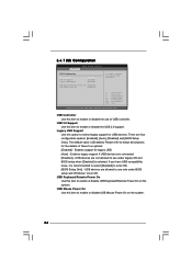
... these four options: [Enabled] - There are connected. [Disabled] - USB devices are allowed to use only under legacy OS and BIOS setup when [Disabled] is [Enabled]. The default value is selected. Enables support for USB devices. If you have USB compatibility issue,...enable or disable the USB 2.0 support. USB Controller Use this option to below descriptions for the details of USB controller. 3.4.7 USB Configuration BIOS SETUP UTILITY Advanced USB Configuration USB Controller USB 2.0 Support Legacy USB Support [Enabled] [Enabled] [Enabled] USB Keyboard/Remote Power On [...
... these four options: [Enabled] - There are connected. [Disabled] - USB devices are allowed to use only under legacy OS and BIOS setup when [Disabled] is [Enabled]. The default value is selected. Enables support for USB devices. If you have USB compatibility issue,...enable or disable the USB 2.0 support. USB Controller Use this option to below descriptions for the details of USB controller. 3.4.7 USB Configuration BIOS SETUP UTILITY Advanced USB Configuration USB Controller USB 2.0 Support Legacy USB Support [Enabled] [Enabled] [Enabled] USB Keyboard/Remote Power On [...

User Manual
Page 35
... speed. F1 F9 F10 ESC Select Screen Select Item General Help Load Defaults Save and Exit Exit v02.54 (C) Copyright 1985-2003, American Megatrends, Inc. BIOS SETUP UTILITY Main OC Tweaker Advanced H/W Monitor Boot Security Exit Hardware Health Event Monitoring CPU Temperature M / B Temperature CPU Fan Speed Chassis Fan Speed Power Fan...
... speed. F1 F9 F10 ESC Select Screen Select Item General Help Load Defaults Save and Exit Exit v02.54 (C) Copyright 1985-2003, American Megatrends, Inc. BIOS SETUP UTILITY Main OC Tweaker Advanced H/W Monitor Boot Security Exit Hardware Health Event Monitoring CPU Temperature M / B Temperature CPU Fan Speed Chassis Fan Speed Power Fan...


