
User Manual
Page 13
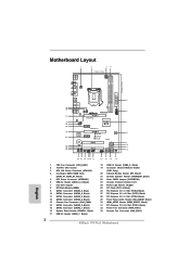
...USB3 Top: RJ-45 DDR3 Front USB 3.0 LAN PHY PWR_FAN1 CHA_FAN1 PCIE1 ErP/EuP Ready AUDIO CODEC HDMI_SPDIF1 1 1 HD_AUDIO1 PCIE2 PCI Express 3.0 P75 Pro3 Intel B75 Super I/O CMOS Battery PCIE4 PCIE3 XFast USB XFast RAM XFast LAN PCI1 64Mb BIOS RoHS SATA3_0 CI1 1 PLED1 1 SPEAKER1 1 1 CLRCMOS1 1...SATA2_4 CHA_FAN2 SATA2_1 SATA2_3 USB3_2_3 1 5 6 7 8 9 10 11 12 22 21 20 1918 17 1 CPU Fan Connector (CPU_FAN1) 2 1155-Pin CPU Socket 3 ATX 12V Power Connector (ATX12V1) 4 2 x 240-pin DDR3 DIMM Slots (DDR3_A1, DDR3_B1, Black) 5 ATX Power Connector (ATXPWR1) 6 USB 3.0 Header...
...USB3 Top: RJ-45 DDR3 Front USB 3.0 LAN PHY PWR_FAN1 CHA_FAN1 PCIE1 ErP/EuP Ready AUDIO CODEC HDMI_SPDIF1 1 1 HD_AUDIO1 PCIE2 PCI Express 3.0 P75 Pro3 Intel B75 Super I/O CMOS Battery PCIE4 PCIE3 XFast USB XFast RAM XFast LAN PCI1 64Mb BIOS RoHS SATA3_0 CI1 1 PLED1 1 SPEAKER1 1 1 CLRCMOS1 1...SATA2_4 CHA_FAN2 SATA2_1 SATA2_3 USB3_2_3 1 5 6 7 8 9 10 11 12 22 21 20 1918 17 1 CPU Fan Connector (CPU_FAN1) 2 1155-Pin CPU Socket 3 ATX 12V Power Connector (ATX12V1) 4 2 x 240-pin DDR3 DIMM Slots (DDR3_A1, DDR3_B1, Black) 5 ATX Power Connector (ATXPWR1) 6 USB 3.0 Header...
User Manual
Page 16
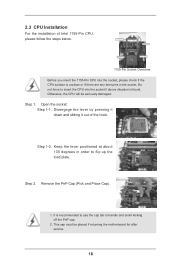
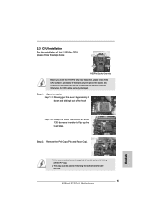
...Lever Contact Array Socket Body 1155-Pin Socket Overview Before you insert the 1155-Pin CPU into the socket if above situation is found. Step 1-2. Otherwise, the CPU will be placed if returning the motherboard for after service. 16 Disengage the lever by pressing it down and sliding it out of Intel 1155-Pin CPU,... please follow the steps below. Step 2. Do not force to insert the CPU into the socket, please check if the CPU surface is recommended to use the cap tab to flip ...
...Lever Contact Array Socket Body 1155-Pin Socket Overview Before you insert the 1155-Pin CPU into the socket if above situation is found. Step 1-2. Otherwise, the CPU will be placed if returning the motherboard for after service. 16 Disengage the lever by pressing it down and sliding it out of Intel 1155-Pin CPU,... please follow the steps below. Step 2. Do not force to insert the CPU into the socket, please check if the CPU surface is recommended to use the cap tab to flip ...
User Manual
Page 18
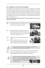
.... Before you install the heatsink, you press down on fastener caps with Intel 1155Pin CPU to the CPU_FAN connector (CPU_ FAN1, see page 13, No. 1). Fan cables on side closest to illustrate the installation of the heatsink for Socket LGA 1155/1156 CPU fan. 18 Please be secured on the motherboard. 2.4 Installation of...
.... Before you install the heatsink, you press down on fastener caps with Intel 1155Pin CPU to the CPU_FAN connector (CPU_ FAN1, see page 13, No. 1). Fan cables on side closest to illustrate the installation of the heatsink for Socket LGA 1155/1156 CPU fan. 18 Please be secured on the motherboard. 2.4 Installation of...
Quick Installation Guide
Page 2
... DDR3 Front USB 3.0 LAN PHY PWR_FAN1 CHA_FAN1 PCIE1 ErP/EuP Ready AUDIO CODEC HDMI_SPDIF1 1 1 HD_AUDIO1 PCIE2 PCI Express 3.0 P75 Pro3 Intel B75 Super I/O CMOS Battery PCIE4 PCIE3 XFast USB XFast RAM XFast LAN PCI1 64Mb BIOS RoHS SATA3_0 CI1 1 PLED1 1 SPEAKER1... 7 8 9 10 11 12 22 21 20 1918 17 16 15 14 13 1 CPU Fan Connector (CPU_FAN1) 2 1155-Pin CPU Socket 3 ATX 12V Power Connector (ATX12V1) 4 2 x 240-pin DDR3 DIMM Slots (DDR3_A1, DDR3_B1, Black) 5 ATX Power Connector ... Power Fan Connector (PWR_FAN1) 33 Chassis Fan Connector (CHA_FAN1) 2 ASRock P75 Pro3 Motherboard English
... DDR3 Front USB 3.0 LAN PHY PWR_FAN1 CHA_FAN1 PCIE1 ErP/EuP Ready AUDIO CODEC HDMI_SPDIF1 1 1 HD_AUDIO1 PCIE2 PCI Express 3.0 P75 Pro3 Intel B75 Super I/O CMOS Battery PCIE4 PCIE3 XFast USB XFast RAM XFast LAN PCI1 64Mb BIOS RoHS SATA3_0 CI1 1 PLED1 1 SPEAKER1... 7 8 9 10 11 12 22 21 20 1918 17 16 15 14 13 1 CPU Fan Connector (CPU_FAN1) 2 1155-Pin CPU Socket 3 ATX 12V Power Connector (ATX12V1) 4 2 x 240-pin DDR3 DIMM Slots (DDR3_A1, DDR3_B1, Black) 5 ATX Power Connector ... Power Fan Connector (PWR_FAN1) 33 Chassis Fan Connector (CHA_FAN1) 2 ASRock P75 Pro3 Motherboard English
Quick Installation Guide
Page 13
... of Intel 1155-Pin CPU, please follow the steps below. Remove the PnP Cap (Pick and Place Cap). This cap must be seriously damaged. It is found. Otherwise, the CPU will be placed if returning the motherboard for after service. 13 ASRock P75 Pro3 Motherboard Step 1-2. Do not force to insert the CPU into the socket...
... of Intel 1155-Pin CPU, please follow the steps below. Remove the PnP Cap (Pick and Place Cap). This cap must be seriously damaged. It is found. Otherwise, the CPU will be placed if returning the motherboard for after service. 13 ASRock P75 Pro3 Motherboard Step 1-2. Do not force to insert the CPU into the socket...
Quick Installation Guide
Page 15
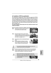
...provides flexible options to adopt three different CPU cooler types, Socket LGA 775, LGA 1155 and LGA 1156. Ensure that the fan cables are securely fastened and in good contact with 1155-Pin socket that the CPU and the heatsink are oriented on side closest ...an example to illustrate the installation of the heatsink for Socket LGA 1155/1156 CPU fan. 15 ASRock P75 Pro3 Motherboard Please adopt the type of heatsink and cooling fan compliant with fan operation or contact other . Ensure that supports Intel 1155-Pin CPUs. Step 5. Step 6. Secure redundant cable...
...provides flexible options to adopt three different CPU cooler types, Socket LGA 775, LGA 1155 and LGA 1156. Ensure that the fan cables are securely fastened and in good contact with 1155-Pin socket that the CPU and the heatsink are oriented on side closest ...an example to illustrate the installation of the heatsink for Socket LGA 1155/1156 CPU fan. 15 ASRock P75 Pro3 Motherboard Please adopt the type of heatsink and cooling fan compliant with fan operation or contact other . Ensure that supports Intel 1155-Pin CPUs. Step 5. Step 6. Secure redundant cable...


