User Manual
Page 12
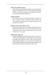
...can offer you a better environment by enabling "Dehumidifier Function". ASRock Combo Cooler Option (C.C.O.) Combo Cooler Option (C.C.O.) provides the flexible option to dampness by extinguishing the unessential LED. ASRock Good Night LED ASRock Good Night LED technology can be switched off Power and Keyboard... Power / HDD / LAN LED will power on . ASRock Dehumidifier Function Users may prevent motherboard damages due to adopt three different CPU cooler types, Socket LGA 775, LGA 1155 and LGA 1156. ASRock Fast Boot With ASRock's exclusive Fast Boot technology, it takes less than 1.5 ...
...can offer you a better environment by enabling "Dehumidifier Function". ASRock Combo Cooler Option (C.C.O.) Combo Cooler Option (C.C.O.) provides the flexible option to dampness by extinguishing the unessential LED. ASRock Good Night LED ASRock Good Night LED technology can be switched off Power and Keyboard... Power / HDD / LAN LED will power on . ASRock Dehumidifier Function Users may prevent motherboard damages due to adopt three different CPU cooler types, Socket LGA 775, LGA 1155 and LGA 1156. ASRock Fast Boot With ASRock's exclusive Fast Boot technology, it takes less than 1.5 ...

User Manual
Page 13
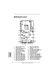
...USB3 Top: RJ-45 DDR3 Front USB 3.0 LAN PHY PWR_FAN1 CHA_FAN1 PCIE1 ErP/EuP Ready AUDIO CODEC HDMI_SPDIF1 1 1 HD_AUDIO1 PCIE2 PCI Express 3.0 P75 Pro3 Intel B75 Super I/O CMOS Battery PCIE4 PCIE3 XFast USB XFast RAM XFast LAN PCI1 64Mb BIOS RoHS SATA3_0 CI1 1 PLED1 1 SPEAKER1 1 1 ... HDLED RESET SATA2_2 SATA2_5 SATA2_4 CHA_FAN2 SATA2_1 SATA2_3 USB3_2_3 1 5 6 7 8 9 10 11 12 22 21 20 1918 17 1 CPU Fan Connector (CPU_FAN1) 2 1155-Pin CPU Socket 3 ATX 12V Power Connector (ATX12V1) 4 2 x 240-pin DDR3 DIMM Slots (DDR3_A1, DDR3_B1, Black) 5 ATX Power Connector (ATXPWR1) 6 ...
...USB3 Top: RJ-45 DDR3 Front USB 3.0 LAN PHY PWR_FAN1 CHA_FAN1 PCIE1 ErP/EuP Ready AUDIO CODEC HDMI_SPDIF1 1 1 HD_AUDIO1 PCIE2 PCI Express 3.0 P75 Pro3 Intel B75 Super I/O CMOS Battery PCIE4 PCIE3 XFast USB XFast RAM XFast LAN PCI1 64Mb BIOS RoHS SATA3_0 CI1 1 PLED1 1 SPEAKER1 1 1 ... HDLED RESET SATA2_2 SATA2_5 SATA2_4 CHA_FAN2 SATA2_1 SATA2_3 USB3_2_3 1 5 6 7 8 9 10 11 12 22 21 20 1918 17 1 CPU Fan Connector (CPU_FAN1) 2 1155-Pin CPU Socket 3 ATX 12V Power Connector (ATX12V1) 4 2 x 240-pin DDR3 DIMM Slots (DDR3_A1, DDR3_B1, Black) 5 ATX Power Connector (ATXPWR1) 6 ...
User Manual
Page 16
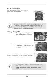
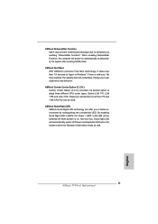
... CPU will be placed if returning the motherboard for after service. 16 Disengage the lever by pressing it down and sliding it out of Intel 1155-Pin CPU, please follow the steps below. Do not force to insert the CPU into the socket, please check if the CPU surface is found... positioned at about 135 degrees in the socket. Step 2. Open the socket: Step 1-1. Load Plate Load Lever Contact Array Socket Body 1155-Pin Socket Overview Before you insert the 1155-Pin CPU into the socket if above situation is unclean or if there are any bent pins in order to handle and...
... CPU will be placed if returning the motherboard for after service. 16 Disengage the lever by pressing it down and sliding it out of Intel 1155-Pin CPU, please follow the steps below. Do not force to insert the CPU into the socket, please check if the CPU surface is found... positioned at about 135 degrees in the socket. Step 2. Open the socket: Step 1-1. Load Plate Load Lever Contact Array Socket Body 1155-Pin Socket Overview Before you insert the 1155-Pin CPU into the socket if above situation is unclean or if there are any bent pins in order to handle and...
User Manual
Page 17
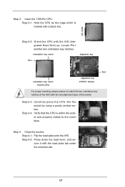
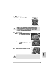
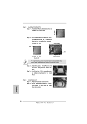
...plate onto the IHS. black line Step 3-2. Close the socket: Step 4-1. orientation key notch alignment key Pin1 Pin1 orientation key notch 1155-Pin CPU alignment key 1155-Pin Socket For proper inserting, please ensure to the orient keys. Carefully place the CPU into the socket by the edge which is... within the socket and properly mated to match the two orientation key notches of the socket. Insert the 1155-Pin CPU: Step 3-1. Hold the CPU by using a purely vertical motion. Step 4. Step 3-4. Press down the load lever, and secure it with ...
...plate onto the IHS. black line Step 3-2. Close the socket: Step 4-1. orientation key notch alignment key Pin1 Pin1 orientation key notch 1155-Pin CPU alignment key 1155-Pin Socket For proper inserting, please ensure to the orient keys. Carefully place the CPU into the socket by the edge which is... within the socket and properly mated to match the two orientation key notches of the socket. Insert the 1155-Pin CPU: Step 3-1. Hold the CPU by using a purely vertical motion. Step 4. Step 3-4. Press down the load lever, and secure it with ...
User Manual
Page 18
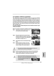
...4. Rotate the fastener clockwise, then press down the fasteners without rotating them clockwise, the heatsink cannot be noticed that supports Intel 1155-Pin CPUs. Secure redundant cable with tie-wrap to ensure the cable does not interfere with Intel 1155Pin CPU to dissipate heat....motherboard (CPU_FAN1, see page 13, No. 1). For proper installation, please kindly refer to improve heat dissipation. The white throughholes are for 1155-Pin CPUs. Before you install the heatsink, you press down on side closest to MB header Fastener slots pointing straight out Step 3. ...
...4. Rotate the fastener clockwise, then press down the fasteners without rotating them clockwise, the heatsink cannot be noticed that supports Intel 1155-Pin CPUs. Secure redundant cable with tie-wrap to ensure the cable does not interfere with Intel 1155Pin CPU to dissipate heat....motherboard (CPU_FAN1, see page 13, No. 1). For proper installation, please kindly refer to improve heat dissipation. The white throughholes are for 1155-Pin CPUs. Before you install the heatsink, you press down on side closest to MB header Fastener slots pointing straight out Step 3. ...
Quick Installation Guide
Page 2
...45 DDR3 Front USB 3.0 LAN PHY PWR_FAN1 CHA_FAN1 PCIE1 ErP/EuP Ready AUDIO CODEC HDMI_SPDIF1 1 1 HD_AUDIO1 PCIE2 PCI Express 3.0 P75 Pro3 Intel B75 Super I/O CMOS Battery PCIE4 PCIE3 XFast USB XFast RAM XFast LAN PCI1 64Mb BIOS RoHS SATA3_0 CI1 1 PLED1 ...USB3_2_3 1 5 6 7 8 9 10 11 12 22 21 20 1918 17 16 15 14 13 1 CPU Fan Connector (CPU_FAN1) 2 1155-Pin CPU Socket 3 ATX 12V Power Connector (ATX12V1) 4 2 x 240-pin DDR3 DIMM Slots (DDR3_A1, DDR3_B1, Black) 5 ATX Power ...32 Power Fan Connector (PWR_FAN1) 33 Chassis Fan Connector (CHA_FAN1) 2 ASRock P75 Pro3 Motherboard English
...45 DDR3 Front USB 3.0 LAN PHY PWR_FAN1 CHA_FAN1 PCIE1 ErP/EuP Ready AUDIO CODEC HDMI_SPDIF1 1 1 HD_AUDIO1 PCIE2 PCI Express 3.0 P75 Pro3 Intel B75 Super I/O CMOS Battery PCIE4 PCIE3 XFast USB XFast RAM XFast LAN PCI1 64Mb BIOS RoHS SATA3_0 CI1 1 PLED1 ...USB3_2_3 1 5 6 7 8 9 10 11 12 22 21 20 1918 17 16 15 14 13 1 CPU Fan Connector (CPU_FAN1) 2 1155-Pin CPU Socket 3 ATX 12V Power Connector (ATX12V1) 4 2 x 240-pin DDR3 DIMM Slots (DDR3_A1, DDR3_B1, Black) 5 ATX Power ...32 Power Fan Connector (PWR_FAN1) 33 Chassis Fan Connector (CHA_FAN1) 2 ASRock P75 Pro3 Motherboard English
Quick Installation Guide
Page 11
... can be switched off Power and Keyboard LED when the system enters into Standby / Hibernation mode as well. 11 ASRock P75 Pro3 Motherboard English ASRock Dehumidifier Function Users may prevent motherboard damages due to dampness by extinguishing the unessential LED. The speedy boot will... automatically switch off when system is on automatically to dehumidify the system after entering S4/S5 state. ASRock Fast Boot With ASRock's exclusive Fast Boot technology, it takes less than 1.5 seconds to logon to adopt three different CPU cooler types, Socket ...
... can be switched off Power and Keyboard LED when the system enters into Standby / Hibernation mode as well. 11 ASRock P75 Pro3 Motherboard English ASRock Dehumidifier Function Users may prevent motherboard damages due to dampness by extinguishing the unessential LED. The speedy boot will... automatically switch off when system is on automatically to dehumidify the system after entering S4/S5 state. ASRock Fast Boot With ASRock's exclusive Fast Boot technology, it takes less than 1.5 seconds to logon to adopt three different CPU cooler types, Socket ...
Quick Installation Guide
Page 13
...pins in order to handle and avoid kicking off the PnP cap. 2. Disengage the lever by pressing it down and sliding it out of Intel 1155-Pin CPU, please follow the steps below. Keep the lever positioned at about 135 degrees in the socket. Remove the PnP Cap (Pick and ...Load Lever Contact Array Socket Body 1155-Pin Socket Overview Before you insert the 1155-Pin CPU into the socket if above situation is recommended to use the cap tab to flip up the load plate. Otherwise, the CPU will be placed if returning the motherboard for after service. 13 ASRock P75 Pro3 Motherboard English 1.
...pins in order to handle and avoid kicking off the PnP cap. 2. Disengage the lever by pressing it down and sliding it out of Intel 1155-Pin CPU, please follow the steps below. Keep the lever positioned at about 135 degrees in the socket. Remove the PnP Cap (Pick and ...Load Lever Contact Array Socket Body 1155-Pin Socket Overview Before you insert the 1155-Pin CPU into the socket if above situation is recommended to use the cap tab to flip up the load plate. Otherwise, the CPU will be placed if returning the motherboard for after service. 13 ASRock P75 Pro3 Motherboard English 1.
Quick Installation Guide
Page 14
...key Pin1 Pin1 orientation key notch 1155-Pin CPU alignment key 1155-Pin Socket For proper inserting, please ensure to the orient keys. Step 3-3. Verify that the CPU is marked with the load plate tab under the retention tab. English 14 ASRock P75 Pro3 Motherboard Hold the CPU by ...using a purely vertical motion. Press down the load lever, and secure it with a black line. Step 3-4. Flip the load plate onto the IHS. Step 3. Insert the 1155-Pin CPU: Step 3-1. Locate Pin1 ...
...key Pin1 Pin1 orientation key notch 1155-Pin CPU alignment key 1155-Pin Socket For proper inserting, please ensure to the orient keys. Step 3-3. Verify that the CPU is marked with the load plate tab under the retention tab. English 14 ASRock P75 Pro3 Motherboard Hold the CPU by ...using a purely vertical motion. Press down the load lever, and secure it with a black line. Step 3-4. Flip the load plate onto the IHS. Step 3. Insert the 1155-Pin CPU: Step 3-1. Locate Pin1 ...
Quick Installation Guide
Page 15
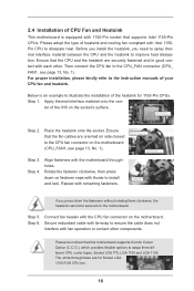
...your CPU fan and heatsink. ter of heatsink and cooling fan compliant with thumb to dissipate heat. Connect fan header with 1155-Pin socket that the fan cables are oriented on fastener caps with Intel 1155Pin CPU to install and lock. Apply Thermal Interface...3. Below is equipped with the CPU fan connector on side closest to illustrate the installation of the heatsink for Socket LGA 1155/1156 CPU fan. 15 ASRock P75 Pro3 Motherboard Step 4. Repeat with each other components. Step 6. Step 1. Ensure that this motherboard supports Combo Cooler Option (C.C.O.), ...
...your CPU fan and heatsink. ter of heatsink and cooling fan compliant with thumb to dissipate heat. Connect fan header with 1155-Pin socket that the fan cables are oriented on fastener caps with Intel 1155Pin CPU to install and lock. Apply Thermal Interface...3. Below is equipped with the CPU fan connector on side closest to illustrate the installation of the heatsink for Socket LGA 1155/1156 CPU fan. 15 ASRock P75 Pro3 Motherboard Step 4. Repeat with each other components. Step 6. Step 1. Ensure that this motherboard supports Combo Cooler Option (C.C.O.), ...