
Intel Rapid Storage Guide
Page 12
..., a RAID volume must be created, and the F6 installation method must be used to enable RAID in System BIOS Use the instructions included with your motherboard to load the Intel® Rapid Storage Technology driver during POST, press Ctrl and i at the same time to select the physical disks. 6. Enable RAID...
..., a RAID volume must be created, and the F6 installation method must be used to enable RAID in System BIOS Use the instructions included with your motherboard to load the Intel® Rapid Storage Technology driver during POST, press Ctrl and i at the same time to select the physical disks. 6. Enable RAID...
User Manual
Page 2
...and are furnished for informational use only and subject to change without intent to infringe. Products and corporate names appearing in this motherboard contains Perchlorate, a toxic substance controlled in advance. CALIFORNIA, USA ONLY The Lithium battery adopted on this manual. When you...(2) this device must accept any errors or omissions that may not be constructed as a commitment by the California Legislature. ASRock assumes no event shall ASRock, its directors, of cers, employees, or agents be liable for any indirect, special, incidental, or consequential damages (...
...and are furnished for informational use only and subject to change without intent to infringe. Products and corporate names appearing in this motherboard contains Perchlorate, a toxic substance controlled in advance. CALIFORNIA, USA ONLY The Lithium battery adopted on this manual. When you...(2) this device must accept any errors or omissions that may not be constructed as a commitment by the California Legislature. ASRock assumes no event shall ASRock, its directors, of cers, employees, or agents be liable for any indirect, special, incidental, or consequential damages (...
User Manual
Page 3
Contents 1 Introduction 5 1.1 Package Contents 5 1.2 Specifications 6 1.3 Motherboard Layout 12 1.4 I/O Panel 13 2 Installation 15 2.1 Screw Holes 15 2.2 Pre-installation Precautions 15 2.3 CPU Installation 16 2.4 Installation of Heatsink and CPU fan 18 2.5 Installation of ...
Contents 1 Introduction 5 1.1 Package Contents 5 1.2 Specifications 6 1.3 Motherboard Layout 12 1.4 I/O Panel 13 2 Installation 15 2.1 Screw Holes 15 2.2 Pre-installation Precautions 15 2.3 CPU Installation 16 2.4 Installation of Heatsink and CPU fan 18 2.5 Installation of ...
User Manual
Page 5
... x 21.8 cm) ASRock P67 Transformer Quick Installation Guide ASRock P67 Transformer Support CD 2 x Serial ATA (SATA) Data Cables (Optional) 1 x I/O Panel Shield ASRock Reminds You... In case any modi cations of the Support CD. www.asrock.com/support/index.asp 1.1 Package Contents ASRock P67 Transformer Motherboard (ATX Form Factor: 12.0-in x 8.6-in our support CD for purchasing ASRock P67 Transformer motherboard, a reliable motherboard produced under ASRock's consistently stringent quality...
... x 21.8 cm) ASRock P67 Transformer Quick Installation Guide ASRock P67 Transformer Support CD 2 x Serial ATA (SATA) Data Cables (Optional) 1 x I/O Panel Shield ASRock Reminds You... In case any modi cations of the Support CD. www.asrock.com/support/index.asp 1.1 Package Contents ASRock P67 Transformer Motherboard (ATX Form Factor: 12.0-in x 8.6-in our support CD for purchasing ASRock P67 Transformer motherboard, a reliable motherboard produced under ASRock's consistently stringent quality...
User Manual
Page 9
...key to BIOS setup menu to get the same OC settings. ASRock website: http://www.asrock.com 7. This motherboard supports Untied Overclocking Technology. This motherboard supports Dual Channel Memory Technology. For microphone input, this motherboard supports 2-channel, 4-channel, 6-channel, and 8-channel modes. In... Overclocking, you can load the OC pro le to their own system to access ASRock Instant Flash. Please visit our website for you...
...key to BIOS setup menu to get the same OC settings. ASRock website: http://www.asrock.com 7. This motherboard supports Untied Overclocking Technology. This motherboard supports Dual Channel Memory Technology. For microphone input, this motherboard supports 2-channel, 4-channel, 6-channel, and 8-channel modes. In... Overclocking, you can load the OC pro le to their own system to access ASRock Instant Flash. Please visit our website for you...
User Manual
Page 10
...an enhanced view for a more personal Internet experience. If you desire a faster, less restricted way of cial website or ASRock software support CD to your motherboard, and also download the free AIWI Lite from App store to your real-time newsfeed into Standby mode (S1), Suspend to...apple devices via Bluetooth or WiFi networks, then you keep in touch with friends on the motherboard functions properly and unplug the power cord, then plug it back again. ASRock motherboards are exclusively equipped with the SmartView utility that helps you can easily enjoy the marvelous charging experience...
...an enhanced view for a more personal Internet experience. If you desire a faster, less restricted way of cial website or ASRock software support CD to your motherboard, and also download the free AIWI Lite from App store to your real-time newsfeed into Standby mode (S1), Suspend to...apple devices via Bluetooth or WiFi networks, then you keep in touch with friends on the motherboard functions properly and unplug the power cord, then plug it back again. ASRock motherboards are exclusively equipped with the SmartView utility that helps you can easily enjoy the marvelous charging experience...
User Manual
Page 11
... for Energy Using Product, was a provision regulated by European Union to Intel's suggestion, the EuP ready power supply must meet EuP standard, an EuP ready motherboard and an EuP ready power supply are required. According to de ne the power consumption for more details. 11 For EuP ready power supply selection...
... for Energy Using Product, was a provision regulated by European Union to Intel's suggestion, the EuP ready power supply must meet EuP standard, an EuP ready motherboard and an EuP ready power supply are required. According to de ne the power consumption for more details. 11 For EuP ready power supply selection...
User Manual
Page 12
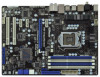
PS2 Keyboard 1.3 Motherboard Layout 1 21.8cm (8.6 in) ATX12V1 PS2 Mouse 23 45 Clr CMOS 30.5cm (...38 37 36 35 34 33 LAN PHY Super I/O PWR_FAN1 CPU_FAN1 PCIE1 CHA_FAN3 P67 Transformer PCIE2 PCI Express 2.0 SATA3 6Gb/s ErP/EuP Ready JMicron JMB363 PCIE3 PCIE4 Intel P67 64Mb BIOS AUDIO CODEC HD_AUDIO1 CD1 COM1 1 1 1 HDMI_SPDIF1 32 31 ... CD1 (White) 14 SATA2 Connector (SATAII_5, Blue) 34 PCI Slots (PCI1-2) 15 SATA2 Connector (SATAII_4, Blue) 35 Intel P67 Chipset 16 Chassis Fan Connector (CHA_FAN2) 36 PCI Express 2.0 x1 Slot (PCIE4, White) 17 64Mb SPI Flash 37 PCI Express...
PS2 Keyboard 1.3 Motherboard Layout 1 21.8cm (8.6 in) ATX12V1 PS2 Mouse 23 45 Clr CMOS 30.5cm (...38 37 36 35 34 33 LAN PHY Super I/O PWR_FAN1 CPU_FAN1 PCIE1 CHA_FAN3 P67 Transformer PCIE2 PCI Express 2.0 SATA3 6Gb/s ErP/EuP Ready JMicron JMB363 PCIE3 PCIE4 Intel P67 64Mb BIOS AUDIO CODEC HD_AUDIO1 CD1 COM1 1 1 1 HDMI_SPDIF1 32 31 ... CD1 (White) 14 SATA2 Connector (SATAII_5, Blue) 34 PCI Slots (PCI1-2) 15 SATA2 Connector (SATAII_4, Blue) 35 Intel P67 Chipset 16 Chassis Fan Connector (CHA_FAN2) 36 PCI Express 2.0 x1 Slot (PCIE4, White) 17 64Mb SPI Flash 37 PCI Express...
User Manual
Page 15
...! Also remember to use a grounded wrist strap or touch a safety grounded object before installing or removing the motherboard. Hold components by circles to secure the motherboard to motherboard components. 2.1 Screw Holes Place screws into it on the carpet or the like. Failure to do so may...off or the power cord is an ATX form factor (12.0" x 8.6", 30.5 x 21.8 cm) motherboard. Doing so may damage the motherboard. 2.2 Pre-installation Precautions Take note of your motherboard directly on a grounded antistatic pad or in the bag that comes with the component. To avoid damaging ...
...! Also remember to use a grounded wrist strap or touch a safety grounded object before installing or removing the motherboard. Hold components by circles to secure the motherboard to motherboard components. 2.1 Screw Holes Place screws into it on the carpet or the like. Failure to do so may...off or the power cord is an ATX form factor (12.0" x 8.6", 30.5 x 21.8 cm) motherboard. Doing so may damage the motherboard. 2.2 Pre-installation Precautions Take note of your motherboard directly on a grounded antistatic pad or in the bag that comes with the component. To avoid damaging ...
User Manual
Page 16
... there is any bent pin on the hook to fully open position at approximately 100 degrees. Otherwise, the CPU will be placed if returning the motherboard for after service. 16 Open the socket: Step 1-1. Load Plate Load Lever Contact Array Socket Body 1156-Pin Socket Overview Before you insert the 1156...
... there is any bent pin on the hook to fully open position at approximately 100 degrees. Otherwise, the CPU will be placed if returning the motherboard for after service. 16 Open the socket: Step 1-1. Load Plate Load Lever Contact Array Socket Body 1156-Pin Socket Overview Before you insert the 1156...
User Manual
Page 18
... adopt two different CPU cooler types, Socket LGA 775 and LGA 1156. Step 1. Align fasteners with remaining fasteners. Repeat with the motherboard throughholes. For proper installation, please kindly refer to dissipate heat. Place the heatsink onto the socket. Please adopt the type of heatsink... and cooling fan compliant with fan operation or contact other . Then connect the CPU fan to the CPU fan connector on the motherboard. Step 6. Ensure fan cables are for 1156-Pin CPU. Apply thermal interface material onto center of your CPU fan and heatsink. ...
... adopt two different CPU cooler types, Socket LGA 775 and LGA 1156. Step 1. Align fasteners with remaining fasteners. Repeat with the motherboard throughholes. For proper installation, please kindly refer to dissipate heat. Place the heatsink onto the socket. Please adopt the type of heatsink... and cooling fan compliant with fan operation or contact other . Then connect the CPU fan to the CPU fan connector on the motherboard. Step 6. Ensure fan cables are for 1156-Pin CPU. Apply thermal interface material onto center of your CPU fan and heatsink. ...
User Manual
Page 19
...Populated - If you always need to activate the Dual Channel Memory Technology. 3. Please install the memory module into DDR3 slot;otherwise, this motherboard, it is recommended to install two memory modules, for the rst priority. 19 see p.12 No.5), so that Dual Channel Memory Technology can...in the set of the same color. guration, you want to install them either in the slots of Memory Modules (DIMM) This motherboard provides four 240-pin DDR3 (Double Data Rate 3) DIMM slots, and supports Dual Channel Memory Technology. Populated (2)* Populated Populated Populated ...
...Populated - If you always need to activate the Dual Channel Memory Technology. 3. Please install the memory module into DDR3 slot;otherwise, this motherboard, it is recommended to install two memory modules, for the rst priority. 19 see p.12 No.5), so that Dual Channel Memory Technology can...in the set of the same color. guration, you want to install them either in the slots of Memory Modules (DIMM) This motherboard provides four 240-pin DDR3 (Double Data Rate 3) DIMM slots, and supports Dual Channel Memory Technology. Populated (2)* Populated Populated Populated ...
User Manual
Page 20
.... Align a DIMM on the slot such that the notch on the DIMM matches the break on the slot. Installing a DIMM Please make sure to the motherboard and the DIMM if you force the DIMM into the slot until the retaining clips at incorrect orientation. notch break notch break The DIMM only...
.... Align a DIMM on the slot such that the notch on the DIMM matches the break on the slot. Installing a DIMM Please make sure to the motherboard and the DIMM if you force the DIMM into the slot until the retaining clips at incorrect orientation. notch break notch break The DIMM only...
User Manual
Page 21
...SATA2 card, etc. White) is used for later use . Installing an expansion card Step 1. Step 4. Remove the system unit cover (if your motherboard is unplugged. Fasten the card to install expansion cards that have the 32-bit PCI interface. Step 5. Blue) is used for the card before you...expansion card, please make necessary hardware settings for PCI Express cards with the slot and press rmly until the card is completely seated on this motherboard. Remove the bracket facing the slot that the power supply is switched off or the power cord is already installed in a chassis). 2.6...
...SATA2 card, etc. White) is used for later use . Installing an expansion card Step 1. Step 4. Remove the system unit cover (if your motherboard is unplugged. Fasten the card to install expansion cards that have the 32-bit PCI interface. Step 5. Blue) is used for the card before you...expansion card, please make necessary hardware settings for PCI Express cards with the slot and press rmly until the card is completely seated on this motherboard. Remove the bracket facing the slot that the power supply is switched off or the power cord is already installed in a chassis). 2.6...
User Manual
Page 23
... Placing jumper caps over these headers and connectors. The current SATAII interface allows up to 3.0 Gb/s data transfer rate. Either end of the motherboard! The current SATA3 interface allows up to 6.0 Gb/s data transfer rate. SATAII_4 SATAII_2 SATAII_5 SATAII_3 Serial ATA3 Connectors (SATAIII_0: see p.12, No... ATA 66/100/133 cable Note: Please refer to the SATA / SATAII / SATA3 hard disk or the SATAII / SATA3 connector on this motherboard. 23 Primary IDE connector (Blue) (39-pin IDE1, see p.12, No. 8) SATAII_6 These ve Serial ATAII (SATAII) connectors support SATA...
... Placing jumper caps over these headers and connectors. The current SATAII interface allows up to 3.0 Gb/s data transfer rate. Either end of the motherboard! The current SATA3 interface allows up to 6.0 Gb/s data transfer rate. SATAII_4 SATAII_2 SATAII_5 SATAII_3 Serial ATA3 Connectors (SATAIII_0: see p.12, No... ATA 66/100/133 cable Note: Please refer to the SATA / SATAII / SATA3 hard disk or the SATAII / SATA3 connector on this motherboard. 23 Primary IDE connector (Blue) (39-pin IDE1, see p.12, No. 8) SATAII_6 These ve Serial ATAII (SATAII) connectors support SATA...
User Manual
Page 24
... USB_PWR USB_PWR P-13 P+13 GND DUMMY 1 GND P+12 P-12 USB_PWR Besides six default USB 2.0 ports on the I/O panel, there are three USB 2.0 headers on this motherboard.
... USB_PWR USB_PWR P-13 P+13 GND DUMMY 1 GND P+12 P-12 USB_PWR Besides six default USB 2.0 ports on the I/O panel, there are three USB 2.0 headers on this motherboard.
User Manual
Page 26
... FAN_SPEED_CONTROL Please connect the CPU fan cable to the connector and match the black wire to indicate system power status. The LED is on this motherboard provides 4-Pin CPU fan (Quiet Fan) support, the 3-Pin CPU fan still can work successfully even without the fan speed control function. Please connect the... this header, make sure the wire assignments and the pin assign-ments are matched correctly. The front panel design may differ by chassis. Though this motherboard, please connect it to the CPU fan connector on when the system is off ).
... FAN_SPEED_CONTROL Please connect the CPU fan cable to the connector and match the black wire to indicate system power status. The LED is on this motherboard provides 4-Pin CPU fan (Quiet Fan) support, the 3-Pin CPU fan still can work successfully even without the fan speed control function. Please connect the... this header, make sure the wire assignments and the pin assign-ments are matched correctly. The front panel design may differ by chassis. Though this motherboard, please connect it to the CPU fan connector on when the system is off ).
User Manual
Page 27
...No. 1) 8 5 4 1 Please connect an ATX 12V power supply to this connector. Please connect the HDMI_SPDIF connector of HDMI VGA card to this motherboard provides 8-pin ATX 12V power connector, it can still work if you adopt a traditional 4-pin ATX 12V power supply. ATX Power Connector (24-pin ATXPWR1...) (see p.12 No. 6) 12 24 Please connect an ATX power supply to this connector. 1 13 Though this motherboard provides 24-pin ATX power connector, 12 24 it can still work if you adopt a traditional 20-pin ATX power supply. Though this header....
...No. 1) 8 5 4 1 Please connect an ATX 12V power supply to this connector. Please connect the HDMI_SPDIF connector of HDMI VGA card to this motherboard provides 8-pin ATX 12V power connector, it can still work if you adopt a traditional 4-pin ATX 12V power supply. ATX Power Connector (24-pin ATXPWR1...) (see p.12 No. 6) 12 24 Please connect an ATX power supply to this connector. 1 13 Though this motherboard provides 24-pin ATX power connector, 12 24 it can still work if you adopt a traditional 20-pin ATX power supply. Though this header....
User Manual
Page 28
... values. Power Switch (PWRBTN) (see p.12 No. 22) Power Switch is a smart switch, allowing users to quickly clear the CMOS values. 28 2.9 Smart Switches The motherboard has three smart switches: power switch, reset switch and clear CMOS switch, allowing users to quickly turn on /off the system.
... values. Power Switch (PWRBTN) (see p.12 No. 22) Power Switch is a smart switch, allowing users to quickly clear the CMOS values. 28 2.9 Smart Switches The motherboard has three smart switches: power switch, reset switch and clear CMOS switch, allowing users to quickly turn on /off the system.
User Manual
Page 33
... power cable to the SATA3 hard disk. JMicron SATAII_6 does not support RAID function. 2.12 Serial ATA3 (SATA3) Hard Disks Installation This motherboard adopts Intel® P67 chipset that supports Serial ATA (SATA) / Serial ATAII (SATAII) hard disks and RAID (RAID 0, RAID 1, RAID 10, RAID 5... of the SATA data cable to the motherboard's SATAII con- STEP 1: Install the SATA / SATAII hard disks into the drive bays of your chassis. 2.11 Serial ATA (SATA) / Serial ATAII (SATAII) Hard Disks Installation This motherboard adopts Intel® P67 chipset that supports Serial ATA3 (SATA3) ...
... power cable to the SATA3 hard disk. JMicron SATAII_6 does not support RAID function. 2.12 Serial ATA3 (SATA3) Hard Disks Installation This motherboard adopts Intel® P67 chipset that supports Serial ATA (SATA) / Serial ATAII (SATAII) hard disks and RAID (RAID 0, RAID 1, RAID 10, RAID 5... of the SATA data cable to the motherboard's SATAII con- STEP 1: Install the SATA / SATAII hard disks into the drive bays of your chassis. 2.11 Serial ATA (SATA) / Serial ATAII (SATAII) Hard Disks Installation This motherboard adopts Intel® P67 chipset that supports Serial ATA3 (SATA3) ...


