User Manual
Page 5
... information of this motherboard, please visit our website for details. 5 ASRock website http://www.asrock.com If you for purchasing ASRock P67 Transformer motherboard, a reliable motherboard produced under ASRock's consistently stringent quality control. Chapter 1: Introduction Thank you require technical support...to set the BIOS option in , 30.5 cm x 21.8 cm) ASRock P67 Transformer Quick Installation Guide ASRock P67 Transformer Support CD 2 x Serial ATA (SATA) Data Cables (Optional) 1 x I/O Panel Shield ASRock Reminds You... In this manual will be subject to quality and endurance. ...
... information of this motherboard, please visit our website for details. 5 ASRock website http://www.asrock.com If you for purchasing ASRock P67 Transformer motherboard, a reliable motherboard produced under ASRock's consistently stringent quality control. Chapter 1: Introduction Thank you require technical support...to set the BIOS option in , 30.5 cm x 21.8 cm) ASRock P67 Transformer Quick Installation Guide ASRock P67 Transformer Support CD 2 x Serial ATA (SATA) Data Cables (Optional) 1 x I/O Panel Shield ASRock Reminds You... In this manual will be subject to quality and endurance. ...
Quick Installation Guide
Page 1
... battery in California, USA, please follow the related regulations in any form or by the California Legislature. All rights reserved. 1 ASRock P67 Transformer Motherboard English Disclaimer: Specifications and information contained in this guide are used only for identification or explanation and to... the contents of this guide, ASRock does not provide warranty of any interference received, including interference that may appear in this guide. This device complies with Part ...
... battery in California, USA, please follow the related regulations in any form or by the California Legislature. All rights reserved. 1 ASRock P67 Transformer Motherboard English Disclaimer: Specifications and information contained in this guide are used only for identification or explanation and to... the contents of this guide, ASRock does not provide warranty of any interference received, including interference that may appear in this guide. This device complies with Part ...
Quick Installation Guide
Page 2
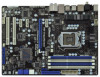
... 36 35 34 33 LAN PHY Super I/O PWR_FAN1 CPU_FAN1 PCIE1 CHA_FAN3 P67 Transformer PCIE2 PCI Express 2.0 SATA3 6Gb/s ErP/EuP Ready JMicron JMB363 PCIE3 PCIE4 Intel P67 64Mb BIOS AUDIO CODEC HD_AUDIO1 CD1 COM1 1 1 1 HDMI_SPDIF1 32 ...(White) 14 SATA2 Connector (SATAII_5, Blue) 34 PCI Slots (PCI1-2) 15 SATA2 Connector (SATAII_4, Blue) 35 Intel P67 Chipset 16 Chassis Fan Connector (CHA_FAN2) 36 PCI Express 2.0 x1 Slot (PCIE4, White) 17 64Mb SPI Flash 37 PCI... (PCIE1, White) 20 Reset Switch (RSTBTN) 40 Power Fan Connector (PWR_FAN1) 2 ASRock P67 Transformer Motherboard English
... 36 35 34 33 LAN PHY Super I/O PWR_FAN1 CPU_FAN1 PCIE1 CHA_FAN3 P67 Transformer PCIE2 PCI Express 2.0 SATA3 6Gb/s ErP/EuP Ready JMicron JMB363 PCIE3 PCIE4 Intel P67 64Mb BIOS AUDIO CODEC HD_AUDIO1 CD1 COM1 1 1 1 HDMI_SPDIF1 32 ...(White) 14 SATA2 Connector (SATAII_5, Blue) 34 PCI Slots (PCI1-2) 15 SATA2 Connector (SATAII_4, Blue) 35 Intel P67 Chipset 16 Chassis Fan Connector (CHA_FAN2) 36 PCI Express 2.0 x1 Slot (PCIE4, White) 17 64Mb SPI Flash 37 PCI... (PCIE1, White) 20 Reset Switch (RSTBTN) 40 Power Fan Connector (PWR_FAN1) 2 ASRock P67 Transformer Motherboard English
Quick Installation Guide
Page 3
... next to the table below for Audio Output Connection Audio Output Channels Front Speaker Rear Speaker Central / Bass Side Speaker (No. 9) (No. 6) (No. 7) (No. 5) 2 V -- -- -- 4 V V -- -- 6 V V V -- 8 V V V V English 3 ASRock P67 Transformer Motherboard TABLE for connection details in accordance with the type of speaker you use . See the table below for the LAN port LED indications. Please...
... next to the table below for Audio Output Connection Audio Output Channels Front Speaker Rear Speaker Central / Bass Side Speaker (No. 9) (No. 6) (No. 7) (No. 5) 2 V -- -- -- 4 V V -- -- 6 V V V -- 8 V V V V English 3 ASRock P67 Transformer Motherboard TABLE for connection details in accordance with the type of speaker you use . See the table below for the LAN port LED indications. Please...
Quick Installation Guide
Page 4
Please select "Mixer ToolBox" , click "Enable playback multi-streaming", and click "ok". To enable Multi-Streaming function, you are allowed to select "Realtek HDA Primary output" to use Rear Speaker, Central/Bass, and Front Speaker, or select "Realtek HDA Audio 2nd output" to the front panel audio header. Choose "2CH", "4CH", "6CH", or "8CH" and then you need to connect a front panel audio cable to use front panel audio. English 4 ASRock P67 Transformer Motherboard After restarting your computer, you will find "Mixer" tool on your system.
Please select "Mixer ToolBox" , click "Enable playback multi-streaming", and click "ok". To enable Multi-Streaming function, you are allowed to select "Realtek HDA Primary output" to use Rear Speaker, Central/Bass, and Front Speaker, or select "Realtek HDA Audio 2nd output" to the front panel audio header. Choose "2CH", "4CH", "6CH", or "8CH" and then you need to connect a front panel audio cable to use front panel audio. English 4 ASRock P67 Transformer Motherboard After restarting your computer, you will find "Mixer" tool on your system.
Quick Installation Guide
Page 5
...bit / VistaTM / VistaTM 64bit, it is recommended to set the BIOS option in our support CD for details. 5 ASRock P67 Transformer Motherboard English Because the motherboard specifications and the BIOS software might be updated, the content of this motherboard, please... visit our website for purchasing ASRock P67 Transformer motherboard, a reliable motherboard produced under ASRock's consistently stringent quality control. ASRock website http://www.asrock.com If you are using. More detailed information of the motherboard and ...
...bit / VistaTM / VistaTM 64bit, it is recommended to set the BIOS option in our support CD for details. 5 ASRock P67 Transformer Motherboard English Because the motherboard specifications and the BIOS software might be updated, the content of this motherboard, please... visit our website for purchasing ASRock P67 Transformer motherboard, a reliable motherboard produced under ASRock's consistently stringent quality control. ASRock website http://www.asrock.com If you are using. More detailed information of the motherboard and ...
Quick Installation Guide
Page 6
... 2.0 x16 slot (blue @ x16 mode) - 3 x PCI Express 2.0 x1 slots - 2 x PCI slots - 7.1 CH HD Audio with LED English 6 ASRock P67 Transformer Motherboard Supports Wake-On-LAN - Supports Energy Efficient Ethernet 802.3az I /O - ATX Form Factor: 12.0-in x 8.6-in LGA1156 Package - Supports Intel&#...174; Turbo Boost Technology - Intel® P67 - Premium Blu-ray audio support - Max. All Solid Capacitor design (100% Japan-made high-quality Conductive Polymer Capacitors) - Advanced V8 + ...
... 2.0 x16 slot (blue @ x16 mode) - 3 x PCI Express 2.0 x1 slots - 2 x PCI slots - 7.1 CH HD Audio with LED English 6 ASRock P67 Transformer Motherboard Supports Wake-On-LAN - Supports Energy Efficient Ethernet 802.3az I /O - ATX Form Factor: 12.0-in x 8.6-in LGA1156 Package - Supports Intel&#...174; Turbo Boost Technology - Intel® P67 - Premium Blu-ray audio support - Max. All Solid Capacitor design (100% Japan-made high-quality Conductive Polymer Capacitors) - Advanced V8 + ...
Quick Installation Guide
Page 7
... "Plug and Play" - DRAM, PCH, CPU PLL, VTT Voltage Multi-adjustment - Drivers, Utilities, AntiVirus Software (Trial Version), ASRock Software Suite (CyberLink DVD Suite - ASRock Instant Flash (see CAUTION 5) - 2 x SATA3 6.0 Gb/s connectors, support RAID (RAID 0, RAID 1, RAID 10, RAID ... UEFI Legal BIOS with LED - 64Mb AMI BIOS - T. (Intelligent Overclocking Technology) - Trial) - ASRock Extreme Tuning Utility (AXTU) (see CAUTION 8) 7 ASRock P67 Transformer Motherboard English Supports jumperfree - ACPI 1.1 Compliance Wake Up Events - SATA3 USB3.0 Connector Smart Switch BIOS ...
... "Plug and Play" - DRAM, PCH, CPU PLL, VTT Voltage Multi-adjustment - Drivers, Utilities, AntiVirus Software (Trial Version), ASRock Software Suite (CyberLink DVD Suite - ASRock Instant Flash (see CAUTION 5) - 2 x SATA3 6.0 Gb/s connectors, support RAID (RAID 0, RAID 1, RAID 10, RAID ... UEFI Legal BIOS with LED - 64Mb AMI BIOS - T. (Intelligent Overclocking Technology) - Trial) - ASRock Extreme Tuning Utility (AXTU) (see CAUTION 8) 7 ASRock P67 Transformer Motherboard English Supports jumperfree - ACPI 1.1 Compliance Wake Up Events - SATA3 USB3.0 Connector Smart Switch BIOS ...
Quick Installation Guide
Page 8
... (see CAUTION 9) - Voltage Monitoring: +12V, +5V, +3.3V, CPU Vcore OS - English 8 ASRock P67 Transformer Motherboard CPU Frequency Stepless Control (see CAUTION 10) - Boot Failure Guard (B.F.G.) - Good Night LED - Turbo 40 / Turbo 50 Technology Hardware ...your own risk and expense. Combo Cooler Option (C.C.O.) (see CAUTION 14) * For detailed product information, please visit our website: http://www.asrock.com WARNING Please realize that there is a certain risk involved with overclocking, including adjusting the setting in the BIOS, applying Untied Overclocking Technology...
... (see CAUTION 9) - Voltage Monitoring: +12V, +5V, +3.3V, CPU Vcore OS - English 8 ASRock P67 Transformer Motherboard CPU Frequency Stepless Control (see CAUTION 10) - Boot Failure Guard (B.F.G.) - Good Night LED - Turbo 40 / Turbo 50 Technology Hardware ...your own risk and expense. Combo Cooler Option (C.C.O.) (see CAUTION 14) * For detailed product information, please visit our website: http://www.asrock.com WARNING Please realize that there is a certain risk involved with overclocking, including adjusting the setting in the BIOS, applying Untied Overclocking Technology...
Quick Installation Guide
Page 9
...64258;ash drive or hard drive must use FAT32/16/12 file system. 9 ASRock P67 Transformer Motherboard English Please check the table on page 3 for system usage under Windows® 7 / VistaTM / XP. ASRock Extreme Tuning Utility (AXTU) is an all-in-one tool to adjust. Please visit ... the POST or press key to BIOS setup menu to read "Untied Overclocking Technology" on page 15 for optimal system performance. ASRock website: http://www.asrock.com 7. ASRock Instant Flash is a BIOS flash utility embedded in a user-friendly interface, which is no such limitation. 5. Just ...
...64258;ash drive or hard drive must use FAT32/16/12 file system. 9 ASRock P67 Transformer Motherboard English Please check the table on page 3 for system usage under Windows® 7 / VistaTM / XP. ASRock Extreme Tuning Utility (AXTU) is an all-in-one tool to adjust. Please visit ... the POST or press key to BIOS setup menu to read "Untied Overclocking Technology" on page 15 for optimal system performance. ASRock website: http://www.asrock.com 7. ASRock Instant Flash is a BIOS flash utility embedded in a user-friendly interface, which is no such limitation. 5. Just ...
Quick Installation Guide
Page 10
..., we will automatically shutdown. Connecting your PC and apple devices via Bluetooth or WiFi networks, then you to perform over-clocking. ASRock APP Charger allows you can easily enjoy the marvelous charging experience than ever. Although this motherboard offers stepless control, it is just ... first utility to turn your iPhone/iPod touch as iPhone/iPod/iPad Touch, ASRock has prepared a wonderful solution for IE that not all the 775 CPU Fan can be used. 10 ASRock P67 Transformer Motherboard English Simply installing the APP Charger driver, it back again. While CPU overheat...
..., we will automatically shutdown. Connecting your PC and apple devices via Bluetooth or WiFi networks, then you to perform over-clocking. ASRock APP Charger allows you can easily enjoy the marvelous charging experience than ever. Although this motherboard offers stepless control, it is just ... first utility to turn your iPhone/iPod touch as iPhone/iPod/iPad Touch, ASRock has prepared a wonderful solution for IE that not all the 775 CPU Fan can be used. 10 ASRock P67 Transformer Motherboard English Simply installing the APP Charger driver, it back again. While CPU overheat...
Quick Installation Guide
Page 11
... standard, an EuP ready motherboard and an EuP ready power supply are required. According to define the power consumption for more details. 11 ASRock P67 Transformer Motherboard English To meet the standard of the completed system shall be under 100 mA current consumption. EuP, stands for Energy Using Product, was a provision...
... standard, an EuP ready motherboard and an EuP ready power supply are required. According to define the power consumption for more details. 11 ASRock P67 Transformer Motherboard English To meet the standard of the completed system shall be under 100 mA current consumption. EuP, stands for Energy Using Product, was a provision...
Quick Installation Guide
Page 12
... so may damage the motherboard. 2.1 CPU Installation For the installation of the following precautions before you uninstall any bent pin on the socket. English 12 ASRock P67 Transformer Motherboard 2. Unplug the power cord from the wall socket before you insert the 1156-Pin CPU into the socket, please check if the CPU surface...
... so may damage the motherboard. 2.1 CPU Installation For the installation of the following precautions before you uninstall any bent pin on the socket. English 12 ASRock P67 Transformer Motherboard 2. Unplug the power cord from the wall socket before you insert the 1156-Pin CPU into the socket, please check if the CPU surface...
Quick Installation Guide
Page 13
... notch 1156-Pin CPU alignment key 1156-Pin Socket For proper inserting, please ensure to match the two orientation key notches of the socket. 13 ASRock P67 Transformer Motherboard English Step 1. Disengaging the lever by the edges where are marked with the two alignment keys of the CPU with black lines. Rotate the...
... notch 1156-Pin CPU alignment key 1156-Pin Socket For proper inserting, please ensure to match the two orientation key notches of the socket. 13 ASRock P67 Transformer Motherboard English Step 1. Disengaging the lever by the edges where are marked with the two alignment keys of the CPU with black lines. Rotate the...
Quick Installation Guide
Page 14
... the CPU fan connector on the socket surface. Step 3-4. Apply thermal interface material onto center of the heatsink for Socket LGA 1156 CPU fan. 14 ASRock P67 Transformer Motherboard English Ensure fan cables are for 1156-Pin CPU. Carefully place the CPU into the socket by using a purely vertical motion. The white throughholes...
... the CPU fan connector on the socket surface. Step 3-4. Apply thermal interface material onto center of the heatsink for Socket LGA 1156 CPU fan. 14 ASRock P67 Transformer Motherboard English Ensure fan cables are for 1156-Pin CPU. Carefully place the CPU into the socket by using a purely vertical motion. The white throughholes...
Quick Installation Guide
Page 15
... activated. Populated (2)* Populated Populated Populated Populated * For the configuration (2), please install identical DDR3 DIMMs in the slots of the same color. English 15 ASRock P67 Transformer Motherboard see p.2 No.5), so that Dual Channel Memory Technology can be damaged. 4. This motherboard also allows you have to the Dual Channel Memory Confi...
... activated. Populated (2)* Populated Populated Populated Populated * For the configuration (2), please install identical DDR3 DIMMs in the slots of the same color. English 15 ASRock P67 Transformer Motherboard see p.2 No.5), so that Dual Channel Memory Technology can be damaged. 4. This motherboard also allows you have to the Dual Channel Memory Confi...
Quick Installation Guide
Page 16
... fully snap back in one correct orientation. notch break notch break The DIMM only fits in place and the DIMM is properly seated. 16 ASRock P67 Transformer Motherboard English Installing a DIMM Please make sure to the motherboard and the DIMM if you force the DIMM into the slot until the retaining clips...
... fully snap back in one correct orientation. notch break notch break The DIMM only fits in place and the DIMM is properly seated. 16 ASRock P67 Transformer Motherboard English Installing a DIMM Please make sure to the motherboard and the DIMM if you force the DIMM into the slot until the retaining clips...
Quick Installation Guide
Page 17
... on the slot. Keep the screws for PCI Express x16 lane width graphics cards. Align the card connector with screws. Replace the system cover. 17 ASRock P67 Transformer Motherboard English PCIE slots: PCIE1 / PCIE3 / PCIE4 (PCIE x1 slot; Remove the system unit cover (if your motherboard is used for later use . Remove the...
... on the slot. Keep the screws for PCI Express x16 lane width graphics cards. Align the card connector with screws. Replace the system cover. 17 ASRock P67 Transformer Motherboard English PCIE slots: PCIE1 / PCIE3 / PCIE4 (PCIE x1 slot; Remove the system unit cover (if your motherboard is used for later use . Remove the...
Quick Installation Guide
Page 18
... CMOS Switch has the same function as the Clear CMOS jumper. If no jumper cap is placed on pins, the jumper is "Open". English 18 ASRock P67 Transformer Motherboard However, please do the clear-CMOS action. The illustration shows a 3-pin jumper whose pin1 and pin2 are setup. 2.5 Jumpers Setup The illustration shows how...
... CMOS Switch has the same function as the Clear CMOS jumper. If no jumper cap is placed on pins, the jumper is "Open". English 18 ASRock P67 Transformer Motherboard However, please do the clear-CMOS action. The illustration shows a 3-pin jumper whose pin1 and pin2 are setup. 2.5 Jumpers Setup The illustration shows how...
Quick Installation Guide
Page 19
... connect the black end to the IDE devices 80-conductor ATA 66/100/133 cable Note: Please refer to 3.0 Gb/s data transfer rate. English 19 ASRock P67 Transformer Motherboard Primary IDE connector (Blue) (39-pin IDE1, see p.2, No. 10) Serial ATA (SATA) Data Cable (Optional) SATAIII_1 SATAIII_0 These two Serial ATA3 (SATA3) connectors...
... connect the black end to the IDE devices 80-conductor ATA 66/100/133 cable Note: Please refer to 3.0 Gb/s data transfer rate. English 19 ASRock P67 Transformer Motherboard Primary IDE connector (Blue) (39-pin IDE1, see p.2, No. 10) Serial ATA (SATA) Data Cable (Optional) SATAIII_1 SATAIII_0 These two Serial ATA3 (SATA3) connectors...


