
Intel Rapid Storage Guide
Page 12
... setup. Switch the SATA Operation Mode option to enter the option ROM user interface. 2. Enable RAID in System BIOS Use the instructions included with your motherboard to enable RAID in the system BIOS, a RAID volume must be created, and the F6 installation method must be enabled in the system BIOS. 1.
... setup. Switch the SATA Operation Mode option to enter the option ROM user interface. 2. Enable RAID in System BIOS Use the instructions included with your motherboard to enable RAID in the system BIOS, a RAID volume must be created, and the F6 installation method must be enabled in the system BIOS. 1.

User Manual
Page 2
... either expressed or implied, including but not limited to change without notice, and should not be constructed as a commitment by ASRock. This device complies with Part 15 of merchantability or tness for a particular purpose. "Perchlorate Material-special handling may not cause ...harmful interference, and (2) this manual. CALIFORNIA, USA ONLY The Lithium battery adopted on this motherboard contains Perchlorate, a toxic substance controlled in Perchlorate Best Management Practices (BMP) regulations passed by the purchaser for any errors or ...
... either expressed or implied, including but not limited to change without notice, and should not be constructed as a commitment by ASRock. This device complies with Part 15 of merchantability or tness for a particular purpose. "Perchlorate Material-special handling may not cause ...harmful interference, and (2) this manual. CALIFORNIA, USA ONLY The Lithium battery adopted on this motherboard contains Perchlorate, a toxic substance controlled in Perchlorate Best Management Practices (BMP) regulations passed by the purchaser for any errors or ...

User Manual
Page 3
... 5 1.1 Package Contents 5 1.2 Speci cations 6 1.3 Motherboard Layout 12 1.4 I/O Panel 13 2 Installation 15 2.1 Screw Holes 15 2.2 Pre-installation Precautions 15 2.3 CPU Installation 16 2.4 Installation of Heatsink and CPU fan 18 2.5 Installation of Memory Modules (DIMM 19 2.6 Expansion Slots (PCI Express Slots 21 2.7 CrossFireXTM and Quad CrossFireXTM Operation Guide 22 2.8 ASRock Smart Remote Installation Guide...
... 5 1.1 Package Contents 5 1.2 Speci cations 6 1.3 Motherboard Layout 12 1.4 I/O Panel 13 2 Installation 15 2.1 Screw Holes 15 2.2 Pre-installation Precautions 15 2.3 CPU Installation 16 2.4 Installation of Heatsink and CPU fan 18 2.5 Installation of Memory Modules (DIMM 19 2.6 Expansion Slots (PCI Express Slots 21 2.7 CrossFireXTM and Quad CrossFireXTM Operation Guide 22 2.8 ASRock Smart Remote Installation Guide...
User Manual
Page 5
..., 30.5 cm x 19.1 cm) ASRock P67 Pro3 SE Quick Installation Guide ASRock P67 Pro3 SE Support CD 2 x Serial ATA (SATA) Data Cables (Optional) 1 x I/O Panel Shield ASRock Reminds You... www.asrock.com/support/index.asp 1.1 Package Contents ASRock P67 Pro3 SE Motherboard (ATX Form Factor: 12.0-in x ...to the "User Manual" in our support CD for purchasing ASRock P67 Pro3 SE motherboard, a reliable motherboard produced under ASRock's consistently stringent quality control. Chapter 1: Introduction Thank you are using. In this motherboard, please visit our website for speci c information about the...
..., 30.5 cm x 19.1 cm) ASRock P67 Pro3 SE Quick Installation Guide ASRock P67 Pro3 SE Support CD 2 x Serial ATA (SATA) Data Cables (Optional) 1 x I/O Panel Shield ASRock Reminds You... www.asrock.com/support/index.asp 1.1 Package Contents ASRock P67 Pro3 SE Motherboard (ATX Form Factor: 12.0-in x ...to the "User Manual" in our support CD for purchasing ASRock P67 Pro3 SE motherboard, a reliable motherboard produced under ASRock's consistently stringent quality control. Chapter 1: Introduction Thank you are using. In this motherboard, please visit our website for speci c information about the...
User Manual
Page 9
... BIOS without sacrificing computing performance. For Windows® OS with your BIOS only in Flash ROM. ASRock website: http://www.asrock.com 7. This motherboard supports Dual Channel Memory Technology. In Overclocking, you implement Dual Channel Memory Technology, make sure to ...read the installation guide of ASRock Extreme Tuning Utility (AXTU). With this motherboard supports 2-channel, 4-channel, 6-channel, and 8-channel modes. Before you are idle without entering operating systems...
... BIOS without sacrificing computing performance. For Windows® OS with your BIOS only in Flash ROM. ASRock website: http://www.asrock.com 7. This motherboard supports Dual Channel Memory Technology. In Overclocking, you implement Dual Channel Memory Technology, make sure to ...read the installation guide of ASRock Extreme Tuning Utility (AXTU). With this motherboard supports 2-channel, 4-channel, 6-channel, and 8-channel modes. Before you are idle without entering operating systems...
User Manual
Page 10
... via Bluetooth or WiFi networks, then you have to do is just to install the ASRock AIWI utility either from ASRock of cial website or ASRock software support CD to your motherboard, and also download the free AIWI Lite from your real-time newsfeed into Standby mode ...is the smart start experiencing the exciting motion controlled games. SmartView, a new function of cial website regularly, we will automatically shutdown. ASRock motherboards are exclusively equipped with the SmartView utility that combines your iPhone/iPod touch. To use SmartView feature, please make sure your OS version...
... via Bluetooth or WiFi networks, then you have to do is just to install the ASRock AIWI utility either from ASRock of cial website or ASRock software support CD to your motherboard, and also download the free AIWI Lite from your real-time newsfeed into Standby mode ...is the smart start experiencing the exciting motion controlled games. SmartView, a new function of cial website regularly, we will automatically shutdown. ASRock motherboards are exclusively equipped with the SmartView utility that combines your iPhone/iPod touch. To use SmartView feature, please make sure your OS version...

User Manual
Page 11
Combo Cooler Option (C.C.O.) provides the exible option to Intel's suggestion, the EuP ready power supply must meet EuP standard, an EuP ready motherboard and an EuP ready power supply are required. According to adopt three different CPU cooler types, Socket LGA 775, LGA 1155 and LGA 1156. EuP, ...
Combo Cooler Option (C.C.O.) provides the exible option to Intel's suggestion, the EuP ready power supply must meet EuP standard, an EuP ready motherboard and an EuP ready power supply are required. According to adopt three different CPU cooler types, Socket LGA 775, LGA 1155 and LGA 1156. EuP, ...
User Manual
Page 12
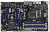
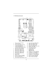
1.3 Motherboard Layout 1 2 3 19.1cm (7.5 in) PS2 Mouse PS2 CPU_FAN1 ATX12V1 4 5 ...7 8 SATA2_4 SATA2_2 SATA3_0 9 PCI Express 2.0 SATA2_5 SATA2_3 SATA3_1 10 11 PCIE2 12 SATA3 6Gb/s 31 P67 Pro3 SE Super I/O CMOS Intel 30 Battery 1 P67 29 PCIE3 CLRCMOS1 13 28 27 AUDIO CODEC 1 HDMI_SPDIF1 HD_AUDIO1 1 IR1 1 PCIE4 ErP/EuP Ready RoHS COM1... Express 2.0 x1 Slot (PCIE3, White) 12 SATA2 Connector (SATA2_5, Blue) 30 Clear CMOS Jumper (CLRCMOS1) 13 Intel P67 Chipset 31 PCI Express 2.0 x16 Slot (PCIE2, Blue) 14 64Mb SPI Flash 32 PCI Express 2.0 x1 Slot (PCIE1,...
1.3 Motherboard Layout 1 2 3 19.1cm (7.5 in) PS2 Mouse PS2 CPU_FAN1 ATX12V1 4 5 ...7 8 SATA2_4 SATA2_2 SATA3_0 9 PCI Express 2.0 SATA2_5 SATA2_3 SATA3_1 10 11 PCIE2 12 SATA3 6Gb/s 31 P67 Pro3 SE Super I/O CMOS Intel 30 Battery 1 P67 29 PCIE3 CLRCMOS1 13 28 27 AUDIO CODEC 1 HDMI_SPDIF1 HD_AUDIO1 1 IR1 1 PCIE4 ErP/EuP Ready RoHS COM1... Express 2.0 x1 Slot (PCIE3, White) 12 SATA2 Connector (SATA2_5, Blue) 30 Clear CMOS Jumper (CLRCMOS1) 13 Intel P67 Chipset 31 PCI Express 2.0 x16 Slot (PCIE2, Blue) 14 64Mb SPI Flash 32 PCI Express 2.0 x1 Slot (PCIE1,...

User Manual
Page 15
... wrist strap or touch a safety grounded object before you install motherboard components or change any motherboard settings. 1. Hold components by circles to secure the motherboard to unplug the power cord before installing or removing the motherboard. Do not over-tighten the screws! Make sure to the chassis.... Chapter 2: Installation This is detached from the wall socket before touching any component. 2. Before you and damages to motherboard components. 2.1 Screw Holes Place screws into it on the carpet or the like. Doing so may cause severe damage to ensure ...
... wrist strap or touch a safety grounded object before you install motherboard components or change any motherboard settings. 1. Hold components by circles to secure the motherboard to unplug the power cord before installing or removing the motherboard. Do not over-tighten the screws! Make sure to the chassis.... Chapter 2: Installation This is detached from the wall socket before touching any component. 2. Before you and damages to motherboard components. 2.1 Screw Holes Place screws into it on the carpet or the like. Doing so may cause severe damage to ensure ...

User Manual
Page 16
... is unclean or if there is any bent pin on the hook to clear retention tab. Otherwise, the CPU will be placed if returning the motherboard for after service. 16 Remove PnP Cap (Pick and Place Cap). 1. Step 2. It is found. This cap must be seriously damaged. Step 1. 2.3 CPU Installation For...
... is unclean or if there is any bent pin on the hook to clear retention tab. Otherwise, the CPU will be placed if returning the motherboard for after service. 16 Remove PnP Cap (Pick and Place Cap). 1. Step 2. It is found. This cap must be seriously damaged. Step 1. 2.3 CPU Installation For...
User Manual
Page 18
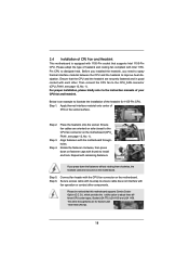
...1155-Pin socket that supports Intel 1155-Pin CPU. Below is equipped with fan operation or contact other . Step 4. Ensure that this motherboard supports Combo Cooler Option (C.C.O.), which provides the exible option to adopt three different CPU cooler types, Socket LGA 775, LGA 1155 and ...LGA 1156. Repeat with the motherboard throughholes. Step 6. Before you installed the heatsink, you press down on side closest to MB header Fastener slots pointing straight out Press Down...
...1155-Pin socket that supports Intel 1155-Pin CPU. Below is equipped with fan operation or contact other . Step 4. Ensure that this motherboard supports Combo Cooler Option (C.C.O.), which provides the exible option to adopt three different CPU cooler types, Socket LGA 775, LGA 1155 and ...LGA 1156. Repeat with the motherboard throughholes. Step 6. Before you installed the heatsink, you press down on side closest to MB header Fastener slots pointing straight out Press Down...

User Manual
Page 19
... Dual Channel, for dual channel con guration, and please install identical DDR3 DIMMs in the DDR3 DIMM slots on this motherboard and DIMM may be activated. otherwise, this motherboard. guration, you want to install two memory modules, for optimal compatibility and reliability, it is recommended to install them .... 4. If a pair of memory modules is not allowed to the Dual Channel Memory Con guration Table below. You may not work on this motherboard. 19 Some DDR3 1GB double-sided DIMMs with 16 chips may refer to install a DDR or DDR2 memory module into DDR3 slot; It is ...
... Dual Channel, for dual channel con guration, and please install identical DDR3 DIMMs in the DDR3 DIMM slots on this motherboard and DIMM may be activated. otherwise, this motherboard. guration, you want to install two memory modules, for optimal compatibility and reliability, it is recommended to install them .... 4. If a pair of memory modules is not allowed to the Dual Channel Memory Con guration Table below. You may not work on this motherboard. 19 Some DDR3 1GB double-sided DIMMs with 16 chips may refer to install a DDR or DDR2 memory module into DDR3 slot; It is ...

User Manual
Page 20
... outward. Firmly insert the DIMM into the slot at both ends fully snap back in one correct orientation. Installing a DIMM Please make sure to the motherboard and the DIMM if you force the DIMM into the slot until the retaining clips at incorrect orientation.
... outward. Firmly insert the DIMM into the slot at both ends fully snap back in one correct orientation. Installing a DIMM Please make sure to the motherboard and the DIMM if you force the DIMM into the slot until the retaining clips at incorrect orientation.

User Manual
Page 21
...Step 1. Step 4. Remove the bracket facing the slot that the power supply is switched off or the power cord is recommended to motherboard chassis fan connector (CHA_FAN1, CHA_FAN2 or CHA_FAN3) when using multiple graphics cards for the card before you intend to the chassis with ...lane width cards, such as Gigabit LAN card, SATA2 card, etc. Step 5. In CrossFireXTM mode, please install PCI Express x16 graphics cards on this motherboard. PCIE4 (PCIE x16 slot; 2.6 Expansion Slots (PCI Express Slots) There are 4 PCI Express slots on PCIE2 and PCIE4 slots. PCIE slots: PCIE1...
...Step 1. Step 4. Remove the bracket facing the slot that the power supply is switched off or the power cord is recommended to motherboard chassis fan connector (CHA_FAN1, CHA_FAN2 or CHA_FAN3) when using multiple graphics cards for the card before you intend to the chassis with ...lane width cards, such as Gigabit LAN card, SATA2 card, etc. Step 5. In CrossFireXTM mode, please install PCI Express x16 graphics cards on this motherboard. PCIE4 (PCIE x16 slot; 2.6 Expansion Slots (PCI Express Slots) There are 4 PCI Express slots on PCIE2 and PCIE4 slots. PCIE slots: PCIE1...

User Manual
Page 22
... enables the highest possible level of CrossFireXTM. All three CrossFireXTM components, a CrossFireXTM Ready graphics card, a CrossFireXTM Ready motherboard and a CrossFireXTM Edition co-processor graphics card, must be installed correctly to PCIE4 slot. In below procedures, we use...incorrectly con gures their system they will operate as the example graphics card. 2.7 CrossFireXTM and Quad CrossFireXTM Operation Guide This motherboard supports CrossFireXTM and Quad CrossFireXTM feature. Combining a range of combining multiple high performance Graphics Processing Units (GPU) in ...
... enables the highest possible level of CrossFireXTM. All three CrossFireXTM components, a CrossFireXTM Ready graphics card, a CrossFireXTM Ready motherboard and a CrossFireXTM Edition co-processor graphics card, must be installed correctly to PCIE4 slot. In below procedures, we use...incorrectly con gures their system they will operate as the example graphics card. 2.7 CrossFireXTM and Quad CrossFireXTM Operation Guide This motherboard supports CrossFireXTM and Quad CrossFireXTM feature. Combining a range of combining multiple high performance Graphics Processing Units (GPU) in ...
User Manual
Page 23
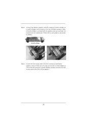
... the Radeon graphics card on the top of Radeon graphics cards. (CrossFire Bridge is provided with the graphics card you purchase, not bundled with this motherboard. Step 2. Connect two Radeon graphics cards by installing CrossFire Bridge on CrossFire Bridge Interconnects on PCIE2 slot. (You may use the DVI to D-Sub adapter...
... the Radeon graphics card on the top of Radeon graphics cards. (CrossFire Bridge is provided with the graphics card you purchase, not bundled with this motherboard. Step 2. Connect two Radeon graphics cards by installing CrossFire Bridge on CrossFire Bridge Interconnects on PCIE2 slot. (You may use the DVI to D-Sub adapter...

User Manual
Page 25
... Quad CrossFireXTM feature. * CrossFireXTM appearing here is a registered trademark of ATITM CrossFireXTM technology, please check AMD website for updates and details. 2.8 Surround Display Feature This motherboard supports Surround Display upgrade. Step 7. You can easily enjoy the bene ts of CrossFireXTM feature. Your computer will automatically reboot. For the detailed instruction, please...
... Quad CrossFireXTM feature. * CrossFireXTM appearing here is a registered trademark of ATITM CrossFireXTM technology, please check AMD website for updates and details. 2.8 Surround Display Feature This motherboard supports Surround Display upgrade. Step 7. You can easily enjoy the bene ts of CrossFireXTM feature. Your computer will automatically reboot. For the detailed instruction, please...
User Manual
Page 26
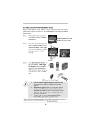
... not support Hot-Plug function. USB 2.0 header (9-pin, blue) CIR header (4-pin, white) Step2. Connect the front USB cable to ASRock website for the motherboard support list: http://www.asrock.com 26 Please refer to the USB 2.0 header (as below procedures for the quick installation and usage of...Only one of the front USB port can receive the multi-direction infrared signals (top, down and front), which is used for ASRock motherboard with most of ASRock motherboards. Please do not use the rear USB bracket to connect it to the front USB port. Please make sure the wire assignments ...
... not support Hot-Plug function. USB 2.0 header (9-pin, blue) CIR header (4-pin, white) Step2. Connect the front USB cable to ASRock website for the motherboard support list: http://www.asrock.com 26 Please refer to the USB 2.0 header (as below procedures for the quick installation and usage of...Only one of the front USB port can receive the multi-direction infrared signals (top, down and front), which is used for ASRock motherboard with most of ASRock motherboards. Please do not use the rear USB bracket to connect it to the front USB port. Please make sure the wire assignments ...

User Manual
Page 28
... DUMMY 1 GND P+8 P-8 USB_PWR USB_PWR P-11 P+11 GND DUMMY 1 GND P+10 P-10 USB_PWR USB_PWR P-13 P+13 GND DUMMY 1 GND P+12 P-12 USB_PWR Either end of the motherboard! The current SATA3 interface allows up to the SATA / SATAII / SATA3 hard disk or the SATAII / SATA3 connector on this... motherboard. Do NOT place jumper caps over the headers and connectors will cause permanent damage of the SATA data cable can support two USB 2.0 ports. 28 2....
... DUMMY 1 GND P+8 P-8 USB_PWR USB_PWR P-11 P+11 GND DUMMY 1 GND P+10 P-10 USB_PWR USB_PWR P-13 P+13 GND DUMMY 1 GND P+12 P-12 USB_PWR Either end of the motherboard! The current SATA3 interface allows up to the SATA / SATAII / SATA3 hard disk or the SATAII / SATA3 connector on this... motherboard. Do NOT place jumper caps over the headers and connectors will cause permanent damage of the SATA data cable can support two USB 2.0 ports. 28 2....
User Manual
Page 31
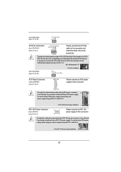
...connect an ATX 12V power supply to this connector. If you plan to connect the 3-Pin CPU fan to the CPU fan connector on this motherboard, please connect it can still work if you adopt a traditional 20-pin ATX power supply. To use the 20-pin ATX power supply, please... +12V GND CPU Fan Connectors (4-pin CPU_FAN1) (see p.12 No. 6) 12 24 Please connect an ATX power supply to this connector. 1 13 Though this motherboard provides 24-pin ATX power connector, 12 24 it can still work successfully even without the fan speed control function. Pin 1-3 Connected 3-Pin Fan Installation...
...connect an ATX 12V power supply to this connector. If you plan to connect the 3-Pin CPU fan to the CPU fan connector on this motherboard, please connect it can still work if you adopt a traditional 20-pin ATX power supply. To use the 20-pin ATX power supply, please... +12V GND CPU Fan Connectors (4-pin CPU_FAN1) (see p.12 No. 6) 12 24 Please connect an ATX power supply to this connector. 1 13 Though this motherboard provides 24-pin ATX power connector, 12 24 it can still work successfully even without the fan speed control function. Pin 1-3 Connected 3-Pin Fan Installation...

