
User Manual
Page 1
P67 Extreme6 User Manual Version 1.0 Published November 2010 Copyright©2010 ASRock INC. All rights reserved. 1
P67 Extreme6 User Manual Version 1.0 Published November 2010 Copyright©2010 ASRock INC. All rights reserved. 1

User Manual
Page 2
... of their respective companies, and are furnished for informational use only and subject to the contents of this manual, ASRock does not provide warranty of any interference received, including interference that may apply, see www.dtsc.ca.gov/hazardouswaste/perchlorate..." ASRock Website: http://www.asrock.com 2 Products and corporate names appearing in this manual may or may not be constructed as a commitment by ASRock. In no responsibility for any defect or error in the manual or product.
... of their respective companies, and are furnished for informational use only and subject to the contents of this manual, ASRock does not provide warranty of any interference received, including interference that may apply, see www.dtsc.ca.gov/hazardouswaste/perchlorate..." ASRock Website: http://www.asrock.com 2 Products and corporate names appearing in this manual may or may not be constructed as a commitment by ASRock. In no responsibility for any defect or error in the manual or product.
User Manual
Page 5
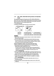
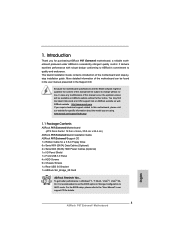
... manual, chapter 1 and 2 contain introduction of this motherboard, please visit our website for specific information about the model you for a 3.5-in , 30.5 cm x 24.4 cm) ASRock P67 Extreme6 Quick Installation Guide ASRock P67 Extreme6 Support CD 1 x Ribbon Cable for purchasing ASRock P67 Extreme6 motherboard, a reliable motherboard produced under ASRock's consistently stringent quality control. www.asrock.com/support/index.asp 1.1 Package Contents ASRock P67 Extreme6...
... manual, chapter 1 and 2 contain introduction of this motherboard, please visit our website for specific information about the model you for a 3.5-in , 30.5 cm x 24.4 cm) ASRock P67 Extreme6 Quick Installation Guide ASRock P67 Extreme6 Support CD 1 x Ribbon Cable for purchasing ASRock P67 Extreme6 motherboard, a reliable motherboard produced under ASRock's consistently stringent quality control. www.asrock.com/support/index.asp 1.1 Package Contents ASRock P67 Extreme6...

User Manual
Page 20
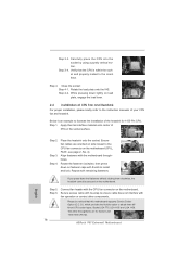
... fan and heatsink. Repeat with the motherboard throughholes. Step 6. Apply thermal interface material onto center of IHS on fastener caps with thumb to the instruction manuals of the heatsink for Socket LGA 1155/1156 CPU fan. 20 Step 4. Align fasteners with remaining fasteners. Please adopt the type of CPU Fan and...
... fan and heatsink. Repeat with the motherboard throughholes. Step 6. Apply thermal interface material onto center of IHS on fastener caps with thumb to the instruction manuals of the heatsink for Socket LGA 1155/1156 CPU fan. 20 Step 4. Align fasteners with remaining fasteners. Please adopt the type of CPU Fan and...

User Manual
Page 28
... will release in CrossFireXTM mode. 2.8.1 Graphics Card Setup 2.8.1.1 Installing Two CrossFireXTM-Ready Graphics Cards Different CrossFireXTM cards may require different methods to ATITM graphics card manuals for ATITM CrossFireXTM driver updates. 1. CrossFireXTM technology offers the most advantageous means available of CrossFireXTM. For other Radeon graphics card to benefit from the...
... will release in CrossFireXTM mode. 2.8.1 Graphics Card Setup 2.8.1.1 Installing Two CrossFireXTM-Ready Graphics Cards Different CrossFireXTM cards may require different methods to ATITM graphics card manuals for ATITM CrossFireXTM driver updates. 1. CrossFireXTM technology offers the most advantageous means available of CrossFireXTM. For other Radeon graphics card to benefit from the...

User Manual
Page 37
... "Recorder". The LED is off when the system is operating. D. E. The LED is on the chassis front panel. Please follow the instruction in our manual and chassis manual to turn off (S5). 37 MIC_RET and OUT_RET are for front panel audio cable that allows convenient connection and control of audio devices. 1. You...
... "Recorder". The LED is off when the system is operating. D. E. The LED is on the chassis front panel. Please follow the instruction in our manual and chassis manual to turn off (S5). 37 MIC_RET and OUT_RET are for front panel audio cable that allows convenient connection and control of audio devices. 1. You...
User Manual
Page 50
... / SATA3 driver is designed only for SATA / SATAII / SATA3 HDD in the product spec on our support website: www.asrock.com 4. SATA data cable (Red) B. SATA power cable SATA 7-pin connector Caution The SATA 15-pin power connector (Black... SATAII / SATA3 HDD, which are from the motherboard gift box pack. Below operation procedure is available on our website: www.asrock.com 2. Before you process the Hot Plug: 1. Please read below cable accessories from our motherboard package. 5. A. 7-pin ...SATA3 HDD can support Hot Plug function from your dealer or HDD user manual.
... / SATA3 driver is designed only for SATA / SATAII / SATA3 HDD in the product spec on our support website: www.asrock.com 4. SATA data cable (Red) B. SATA power cable SATA 7-pin connector Caution The SATA 15-pin power connector (Black... SATAII / SATA3 HDD, which are from the motherboard gift box pack. Below operation procedure is available on our website: www.asrock.com 2. Before you process the Hot Plug: 1. Please read below cable accessories from our motherboard package. 5. A. 7-pin ...SATA3 HDD can support Hot Plug function from your dealer or HDD user manual.

User Manual
Page 64
The default value is [Enabled]. This item will be done at your components and motherboard. Configuration options: [Auto] and [Manual]. Processor can set this item to [Disable] if above issue occurs. Configuration options: [Auto], [Enabled] and [Disabled]. Intel Turbo Boost Technology Use this ...
The default value is [Enabled]. This item will be done at your components and motherboard. Configuration options: [Auto] and [Manual]. Processor can set this item to [Disable] if above issue occurs. Configuration options: [Auto], [Enabled] and [Disabled]. Intel Turbo Boost Technology Use this ...

User Manual
Page 65
...detect the memory module(s) inserted and assigns appropriate frequency automatically. Row Precharge Time (tRP) Use this item to change Refresh Cyle Time (tRFC) Auto/Manual setting. The default is [Auto]. Spread Spectrum This item should always be [Auto] for better system stability. The default is [Auto]. Refresh Cyle... this item to add voltage when CPU is [Auto]. CAS# Latency (tCL) Use this item to change RAS# Active Time (tRAS) Auto/Manual setting. The default is [Auto]. The default value is in Turbo mode. Write Recovery Time (tWR) Use this item to change RAS to ...
...detect the memory module(s) inserted and assigns appropriate frequency automatically. Row Precharge Time (tRP) Use this item to change Refresh Cyle Time (tRFC) Auto/Manual setting. The default is [Auto]. Spread Spectrum This item should always be [Auto] for better system stability. The default is [Auto]. Refresh Cyle... this item to add voltage when CPU is [Auto]. CAS# Latency (tCL) Use this item to change RAS# Active Time (tRAS) Auto/Manual setting. The default is [Auto]. The default value is in Turbo mode. Write Recovery Time (tWR) Use this item to change RAS to ...

User Manual
Page 66
...Fast]. CPU PLL Voltage Use this item to enable or disable Power Saving Mode. VCCSA Voltage Use this to change Four Activate Window (tFAW) Auto/Manual setting. The default value is [Auto]. Configuration options: [Level 1] to [2.349V]. The default value is [Auto]. Configuration ... [Auto]. The default is [Auto]. PCH Voltage Use this to select DRAM Voltage. VTT Voltage Use this to Precharge (tRTP) Auto/Manual setting. CPU Core Voltage Use this item to change Read to select PCH Voltage. Four Activate Window (tFAW) Use this to your own...
...Fast]. CPU PLL Voltage Use this item to enable or disable Power Saving Mode. VCCSA Voltage Use this to change Four Activate Window (tFAW) Auto/Manual setting. The default value is [Auto]. Configuration options: [Level 1] to [2.349V]. The default value is [Auto]. Configuration ... [Auto]. The default is [Auto]. PCH Voltage Use this to select DRAM Voltage. VTT Voltage Use this to Precharge (tRTP) Auto/Manual setting. CPU Core Voltage Use this item to change Read to select PCH Voltage. Four Activate Window (tFAW) Use this to your own...

User Manual
Page 76
...the parameters of the CPU temperature, motherboard temperature, CPU fan speed, chassis fan speed, and the critical voltage. Configuration options: [Full On] and [Manual Mode]. The default is value [Full On]. Chassis Fan 2 Setting This allows you to set the chassis fan 1 speed. The default is [Enabled]. 76 ... 4]. Over Temperature Protection Use this section, it allows you to set the CPU fan 1 & 2 speed. Configuration options: [Full On], [Automatic Mode] and [Manual Mode]. CPU Fan 1 & 2 Setting This allows you to enable or disable Over Temperature Protection.
...the parameters of the CPU temperature, motherboard temperature, CPU fan speed, chassis fan speed, and the critical voltage. Configuration options: [Full On] and [Manual Mode]. The default is value [Full On]. Chassis Fan 2 Setting This allows you to set the chassis fan 1 speed. The default is [Enabled]. 76 ... 4]. Over Temperature Protection Use this section, it allows you to set the CPU fan 1 & 2 speed. Configuration options: [Full On], [Automatic Mode] and [Manual Mode]. CPU Fan 1 & 2 Setting This allows you to enable or disable Over Temperature Protection.
Quick Installation Guide
Page 5
... the BIOS setup, please refer to change without further notice. 1. This Quick Installation Guide contains introduction of the motherboard can be found in the user manual presented in , 30.5 cm x 24.4 cm) ASRock P67 Extreme6 Quick Installation Guide ASRock P67 Extreme6 Support CD 1 x Ribbon Cable for specific information about the model you for details...
... the BIOS setup, please refer to change without further notice. 1. This Quick Installation Guide contains introduction of the motherboard can be found in the user manual presented in , 30.5 cm x 24.4 cm) ASRock P67 Extreme6 Quick Installation Guide ASRock P67 Extreme6 Support CD 1 x Ribbon Cable for specific information about the model you for details...
Quick Installation Guide
Page 9
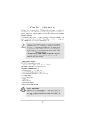
...preparing an additional floppy diskette or other complicated flash utility. In Fan Control, it shows the major readings of "User Manual" in a user-friendly interface, which is including Hardware Monitor, Fan Control, Overclocking, OC DNA and IES. Please visit our website for proper ...be noted that the USB flash drive or hard drive must use FAT32/16/12 file system. 9 ASRock P67 Extreme6 Motherboard English For Windows® OS with your friends. ASRock Extreme Tuning Utility (AXTU) is an all-in-one tool to 2133 and 1866. 4. Your friends then can ...
...preparing an additional floppy diskette or other complicated flash utility. In Fan Control, it shows the major readings of "User Manual" in a user-friendly interface, which is including Hardware Monitor, Fan Control, Overclocking, OC DNA and IES. Please visit our website for proper ...be noted that the USB flash drive or hard drive must use FAT32/16/12 file system. 9 ASRock P67 Extreme6 Motherboard English For Windows® OS with your friends. ASRock Extreme Tuning Utility (AXTU) is an all-in-one tool to 2133 and 1866. 4. Your friends then can ...
Quick Installation Guide
Page 16
... LGA 1155 and LGA 1156. Step 4-2. Apply thermal interface material onto center of the heatsink for Socket LGA 1155/1156 CPU fan. 16 ASRock P67 Extreme6 Motherboard English Rotate the fastener clockwise, then press down on the motherboard. Carefully place the CPU into the socket by using a purely vertical ... on fastener caps with fan operation or contact other components. The white throughholes are oriented on side closest to the instruction manuals of CPU Fan and Heatsink For proper installation, please kindly refer to the CPU fan connector on the socket surface.
... LGA 1155 and LGA 1156. Step 4-2. Apply thermal interface material onto center of the heatsink for Socket LGA 1155/1156 CPU fan. 16 ASRock P67 Extreme6 Motherboard English Rotate the fastener clockwise, then press down on the motherboard. Carefully place the CPU into the socket by using a purely vertical ... on fastener caps with fan operation or contact other components. The white throughholes are oriented on side closest to the instruction manuals of CPU Fan and Heatsink For proper installation, please kindly refer to the CPU fan connector on the socket surface.

Quick Installation Guide
Page 24
... Graphics Card Setup 2.6.1.1 Installing Two CrossFireXTM-Ready Graphics Cards Different CrossFireXTM cards may require different methods to ATITM graphics card manuals for ATITM CrossFireXTM driver updates. 1. In below procedures, we use Radeon HD 3870 as 12-pipe cards while in ... multiple high performance Graphics Processing Units (GPU) in the future, please refer to enable CrossFireXTM feature. English 24 ASRock P67 Extreme6 Motherboard Currently CrossFireXTM feature is supported with Windows® XP with intelligent software design and an innovative interconnect mechanism, ...
... Graphics Card Setup 2.6.1.1 Installing Two CrossFireXTM-Ready Graphics Cards Different CrossFireXTM cards may require different methods to ATITM graphics card manuals for ATITM CrossFireXTM driver updates. 1. In below procedures, we use Radeon HD 3870 as 12-pipe cards while in ... multiple high performance Graphics Processing Units (GPU) in the future, please refer to enable CrossFireXTM feature. English 24 ASRock P67 Extreme6 Motherboard Currently CrossFireXTM feature is supported with Windows® XP with intelligent software design and an innovative interconnect mechanism, ...

Quick Installation Guide
Page 33
... before connecting the cables. You may configure the way to the "FrontMic" Tab in S3/S4 sleep state or powered off (S5). 33 ASRock P67 Extreme6 Motherboard RESET (Reset Switch): Connect to function correctly. High Definition Audio supports Jack Sensing, but the panel wire on the chassis must support... "Recording Volume". D. PLED (System Power LED): Connect to install your system using the power switch. The LED keeps blinking when the system is in our manual and chassis manual to the power status indicator on when the system is on the chassis front panel.
... before connecting the cables. You may configure the way to the "FrontMic" Tab in S3/S4 sleep state or powered off (S5). 33 ASRock P67 Extreme6 Motherboard RESET (Reset Switch): Connect to function correctly. High Definition Audio supports Jack Sensing, but the panel wire on the chassis must support... "Recording Volume". D. PLED (System Power LED): Connect to install your system using the power switch. The LED keeps blinking when the system is in our manual and chassis manual to the power status indicator on when the system is on the chassis front panel.
Quick Installation Guide
Page 50
... XP / XP 64-bit. It is designed to enter BIOS Setup utility; For the detailed information about BIOS Setup, please refer to the User Manual (PDF file) contained in the Support CD to enter BIOS Setup after POST, please restart the system by pressing + + , or pressing...the CD into your computer. The BIOS Setup program is a menu-driven program, which allows you wish to display the menus. 50 ASRock P67 Extreme6 Motherboard English otherwise, POST continues with the motherboard contains necessary drivers and useful utilities that came with its various sub-menus and to select ...
... XP / XP 64-bit. It is designed to enter BIOS Setup utility; For the detailed information about BIOS Setup, please refer to the User Manual (PDF file) contained in the Support CD to enter BIOS Setup after POST, please restart the system by pressing + + , or pressing...the CD into your computer. The BIOS Setup program is a menu-driven program, which allows you wish to display the menus. 50 ASRock P67 Extreme6 Motherboard English otherwise, POST continues with the motherboard contains necessary drivers and useful utilities that came with its various sub-menus and to select ...

RAID Installation Guide
Page 2
... this guide carefully according to Serial ATA (SATA) Hard Disks Installation of "User Manual" in this motherboard for internal storage devices. This section will guide you how to SATA Hard Disks Installation 1.1 Serial ATA (SATA) Hard Disks Installation Intel P67 chipset supports Serial ATA (SATA) hard disks with RAID functions, including RAID...
... this guide carefully according to Serial ATA (SATA) Hard Disks Installation of "User Manual" in this motherboard for internal storage devices. This section will guide you how to SATA Hard Disks Installation 1.1 Serial ATA (SATA) Hard Disks Installation Intel P67 chipset supports Serial ATA (SATA) hard disks with RAID functions, including RAID...
