User Manual
Page 7
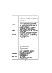
...ATX power connector - 8 pin 12V power connector - AMI UEFI Legal BIOS with eSATA3 port) - 4 x Rear USB 3.0 ports by Etron EJ168A, support USB 1.0/ 2.0/3.0 up to 5Gb/s - 4 x SATA2 3.0 Gb/s connectors, support RAID (RAID 0, RAID 1, RAID 10, RAID 5 and Intel Rapid Storage), NCQ, AHCI and Hot Plug... Dr. Debug (7-Segment Debug LED) - 1 x Clear CMOS Switch with LED - 1 x Power Switch with LED - 1 x Reset Switch with LED - SATA3 USB3.0 Connector Smart Switch BIOS Feature - 1 x eSATA3 Connector - 4 x Ready-to-Use USB 3.0 Ports - 2 x RJ-45 LAN Ports with LED (ACT/LINK LED and SPEED LED) - 1 x IEEE ...
...ATX power connector - 8 pin 12V power connector - AMI UEFI Legal BIOS with eSATA3 port) - 4 x Rear USB 3.0 ports by Etron EJ168A, support USB 1.0/ 2.0/3.0 up to 5Gb/s - 4 x SATA2 3.0 Gb/s connectors, support RAID (RAID 0, RAID 1, RAID 10, RAID 5 and Intel Rapid Storage), NCQ, AHCI and Hot Plug... Dr. Debug (7-Segment Debug LED) - 1 x Clear CMOS Switch with LED - 1 x Power Switch with LED - 1 x Reset Switch with LED - SATA3 USB3.0 Connector Smart Switch BIOS Feature - 1 x eSATA3 Connector - 4 x Ready-to-Use USB 3.0 Ports - 2 x RJ-45 LAN Ports with LED (ACT/LINK LED and SPEED LED) - 1 x IEEE ...
User Manual
Page 8
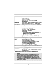
... - ErP/EuP Ready (ErP/EuP ready power supply is a certain risk involved with overclocking, including adjusting the setting in the BIOS, applying Untied Overclocking Technology, or using the third-party overclocking tools. It should be done at your system. ACPI 1.1 Compliance ...even cause damage to the components and devices of your own risk and expense. OEM and Trial) Unique Feature - SMBIOS 2.3.1 Support - ASRock AIWI (see CAUTION 10) - SmartView (see CAUTION 8) - Boot Failure Guard (B.F.G.) - Chassis Temperature Sensing - CPU/Chassis Quiet Fan (Allow Chassis Fan Speed ...
... - ErP/EuP Ready (ErP/EuP ready power supply is a certain risk involved with overclocking, including adjusting the setting in the BIOS, applying Untied Overclocking Technology, or using the third-party overclocking tools. It should be done at your system. ACPI 1.1 Compliance ...even cause damage to the components and devices of your own risk and expense. OEM and Trial) Unique Feature - SMBIOS 2.3.1 Support - ASRock AIWI (see CAUTION 10) - SmartView (see CAUTION 8) - Boot Failure Guard (B.F.G.) - Chassis Temperature Sensing - CPU/Chassis Quiet Fan (Allow Chassis Fan Speed ...

User Manual
Page 14
...Dual GLAN 46 PCIE2 RoHS 64Mb BIOS CrossFireX 45 PCI1 1394a ErP/EuP Ready CLRCMOS1 44 PCIE3 1 CMOS Intel Super I/O Battery PCI Express 2.0 P67 SATA3_0_1 Front USB 3.0 SATA3_M3_M4 SATA3_M1_M2 43 42 41 40 39 PCIE4 P67 Extreme6 PCI2 Designed in Taipei 1 HDMI_SPDIF1 ...Dual Channel: DDR3_A2, DDR3_B2, White) 7 ATX Power Connector (ATXPWR1) 8 Front Panel IEEE 1394 Header (FRONT_1394, White) 9 Power Fan Connector (PWR_FAN1) 10 Chassis Fan Connector (CHA_FAN3) 11 SATA2 Connector (SATA2_5, Blue) 12 SATA2 Connector (SATA2_4, Blue) 13 SATA2 Connector (SATA2_3, Blue) 14 SATA2 Connector ...
...Dual GLAN 46 PCIE2 RoHS 64Mb BIOS CrossFireX 45 PCI1 1394a ErP/EuP Ready CLRCMOS1 44 PCIE3 1 CMOS Intel Super I/O Battery PCI Express 2.0 P67 SATA3_0_1 Front USB 3.0 SATA3_M3_M4 SATA3_M1_M2 43 42 41 40 39 PCIE4 P67 Extreme6 PCI2 Designed in Taipei 1 HDMI_SPDIF1 ...Dual Channel: DDR3_A2, DDR3_B2, White) 7 ATX Power Connector (ATXPWR1) 8 Front Panel IEEE 1394 Header (FRONT_1394, White) 9 Power Fan Connector (PWR_FAN1) 10 Chassis Fan Connector (CHA_FAN3) 11 SATA2 Connector (SATA2_5, Blue) 12 SATA2 Connector (SATA2_4, Blue) 13 SATA2 Connector (SATA2_3, Blue) 14 SATA2 Connector ...

User Manual
Page 34
...for 15 seconds, use a jumper cap to clear the CMOS when you just finish updating the BIOS, you must boot up the system first, and then shut it down before you update the BIOS. FDD connector (33-pin FLOPPY1) (see p.14, No. 32) Setting Default Clear CMOS Description Note:... CLRCMOS1 allows you to default setup, please turn off the computer and unplug the power cord from the power supply. 2.10 Jumpers Setup The illustration shows how jumpers...
...for 15 seconds, use a jumper cap to clear the CMOS when you just finish updating the BIOS, you must boot up the system first, and then shut it down before you update the BIOS. FDD connector (33-pin FLOPPY1) (see p.14, No. 32) Setting Default Clear CMOS Description Note:... CLRCMOS1 allows you to default setup, please turn off the computer and unplug the power cord from the power supply. 2.10 Jumpers Setup The illustration shows how jumpers...

Quick Installation Guide
Page 2
...BIOS CrossFireX 45 PCI1 1394a ErP/EuP Ready CLRCMOS1 44 PCIE3 1 CMOS Intel Super I/O Battery PCI Express 2.0 P67 SATA3_0_1 Front USB 3.0 SATA3_M3_M4 SATA3_M1_M2 43 42 41 40 39 PCIE4 P67 Extreme6..., Blue) 9 Power Fan Connector (PWR_FAN1) 35 USB 3.0 Header (USB3_2_3, Light Blue) 10 Chassis Fan Connector (CHA_FAN3) 36 COM Port Header (COM1) 11 SATA2 Connector (SATA2_5, Blue...P67 Chipset 46 PCI Express 2.0 x16 Slot (PCIE2, Blue) 23 Reset Switch (RSTBTN) 47 PCI Express 2.0 x1 Slot (PCIE1, White) 24 Power Switch (PWRBTN) 48 SLI / XFIRE Power Connector 2 ASRock P67 Extreme6...
...BIOS CrossFireX 45 PCI1 1394a ErP/EuP Ready CLRCMOS1 44 PCIE3 1 CMOS Intel Super I/O Battery PCI Express 2.0 P67 SATA3_0_1 Front USB 3.0 SATA3_M3_M4 SATA3_M1_M2 43 42 41 40 39 PCIE4 P67 Extreme6..., Blue) 9 Power Fan Connector (PWR_FAN1) 35 USB 3.0 Header (USB3_2_3, Light Blue) 10 Chassis Fan Connector (CHA_FAN3) 36 COM Port Header (COM1) 11 SATA2 Connector (SATA2_5, Blue...P67 Chipset 46 PCI Express 2.0 x16 Slot (PCIE2, Blue) 23 Reset Switch (RSTBTN) 47 PCI Express 2.0 x1 Slot (PCIE1, White) 24 Power Switch (PWRBTN) 48 SLI / XFIRE Power Connector 2 ASRock P67 Extreme6...
Quick Installation Guide
Page 7
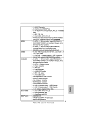
...eSATA3 port) - 4 x Rear USB 3.0 ports by Etron EJ168A, support USB 1.0/ 2.0/3.0 up to 5Gb/s - 4 x SATA2 3.0 Gb/s connectors, support RAID (RAID 0, RAID 1, RAID 10, RAID 5 and Intel Rapid Storage), NCQ, AHCI and Hot Plug functions - 6 x SATA3 6.0Gb/s connectors - 1 x Floppy connector - 1 x IR header - 1 x COM port...- 1 x IEEE 1394 Port - 1 x Clear CMOS Switch with GUI support - AMI UEFI Legal BIOS with LED - SLI/XFire power connector - Supports "Plug and Play" 7 ASRock P67 Extreme6 Motherboard English CPU/Chassis/Power FAN connector - 24 pin ATX power connector - 8 pin 12V power connector...
...eSATA3 port) - 4 x Rear USB 3.0 ports by Etron EJ168A, support USB 1.0/ 2.0/3.0 up to 5Gb/s - 4 x SATA2 3.0 Gb/s connectors, support RAID (RAID 0, RAID 1, RAID 10, RAID 5 and Intel Rapid Storage), NCQ, AHCI and Hot Plug functions - 6 x SATA3 6.0Gb/s connectors - 1 x Floppy connector - 1 x IR header - 1 x COM port...- 1 x IEEE 1394 Port - 1 x Clear CMOS Switch with GUI support - AMI UEFI Legal BIOS with LED - SLI/XFire power connector - Supports "Plug and Play" 7 ASRock P67 Extreme6 Motherboard English CPU/Chassis/Power FAN connector - 24 pin ATX power connector - 8 pin 12V power connector...

Quick Installation Guide
Page 8
...10) - Good Night LED Hardware - CPU Temperature Sensing Monitor - Chassis Temperature Sensing - CPU/Chassis Fan Multi-Speed Control - FCC, CE, WHQL - ErP/EuP Ready (ErP/EuP ready power supply is a certain risk involved with overclocking, including adjusting the setting in the BIOS... of your own risk and expense. English 8 ASRock P67 Extreme6 Motherboard ACPI 1.1 Compliance Wake Up Events - ASRock AIWI (see CAUTION 9) - ASRock APP Charger (see CAUTION 8) - CPU Frequency Stepless Control (see CAUTION 7) - ASRock Instant Flash (see CAUTION 11) - CPU/Chassis...
...10) - Good Night LED Hardware - CPU Temperature Sensing Monitor - Chassis Temperature Sensing - CPU/Chassis Fan Multi-Speed Control - FCC, CE, WHQL - ErP/EuP Ready (ErP/EuP ready power supply is a certain risk involved with overclocking, including adjusting the setting in the BIOS... of your own risk and expense. English 8 ASRock P67 Extreme6 Motherboard ACPI 1.1 Compliance Wake Up Events - ASRock AIWI (see CAUTION 9) - ASRock APP Charger (see CAUTION 8) - CPU Frequency Stepless Control (see CAUTION 7) - ASRock Instant Flash (see CAUTION 11) - CPU/Chassis...
Quick Installation Guide
Page 214
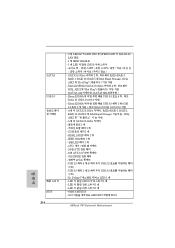
...; 의 SATA2 3.0Gb/s RAID (RAID 0, RAID 1, RAID 10, RAID 5 및 Intel Rapid Storage NCQ, AHCI 6 개 의 SATA3 6.0Gb/s 1 1 개 - HDMI_SPDIF 헤더 1 개 - USB 3.0 헤더 1 개 (2 USB 3.0 2개 ) - Dr. Debug (7 LED) 1 개 - LED 1 개 - 64Mb AMI BIOS - GUI AMI UEFI 적합형 BIOS ASRock P67 Extreme6 Motherboard LED 1 개 - CPU 24 핀 ATX...
...; 의 SATA2 3.0Gb/s RAID (RAID 0, RAID 1, RAID 10, RAID 5 및 Intel Rapid Storage NCQ, AHCI 6 개 의 SATA3 6.0Gb/s 1 1 개 - HDMI_SPDIF 헤더 1 개 - USB 3.0 헤더 1 개 (2 USB 3.0 2개 ) - Dr. Debug (7 LED) 1 개 - LED 1 개 - 64Mb AMI BIOS - GUI AMI UEFI 적합형 BIOS ASRock P67 Extreme6 Motherboard LED 1 개 - CPU 24 핀 ATX...

Quick Installation Guide
Page 243
7. ASRock Instant Flash は、Flash ROM ROM BIOS BIOS より、MS-DOS Windows BIOS POST の間に
7. ASRock Instant Flash は、Flash ROM ROM BIOS BIOS より、MS-DOS Windows BIOS POST の間に

Quick Installation Guide
Page 290
... 0, RAID 1, RAID 10, RAID 5 和 Intel Rapid Storage), NCQ, AHCI 6 x SATA3 6.0Gb/s 接頭 - 1 x 1 x 1 x 1 x HDMI_SPDIF 接頭 - 1 x IEEE 1394 接頭 - 1 x CPU 24 針 ATX 8 針 12V SLI/XFire 4 x USB 2.0 8 USB 2.0 接口 ) - 1 x USB 3.0 2 USB 3.0 接口 ) - 1 x Dr. Debug (7 LED) - 1 個 LED CMOS 1 個 LED 1 個 LED 64Mb AMI BIOS - ACPI 1.1 ASRock P67 Extreme6 Motherboard
... 0, RAID 1, RAID 10, RAID 5 和 Intel Rapid Storage), NCQ, AHCI 6 x SATA3 6.0Gb/s 接頭 - 1 x 1 x 1 x 1 x HDMI_SPDIF 接頭 - 1 x IEEE 1394 接頭 - 1 x CPU 24 針 ATX 8 針 12V SLI/XFire 4 x USB 2.0 8 USB 2.0 接口 ) - 1 x USB 3.0 2 USB 3.0 接口 ) - 1 x Dr. Debug (7 LED) - 1 個 LED CMOS 1 個 LED 1 個 LED 64Mb AMI BIOS - ACPI 1.1 ASRock P67 Extreme6 Motherboard


