User Manual
Page 5
... to the "User Manual" in our support CD for a 3.5-in , 30.5 cm x 24.4 cm) ASRock P67 Extreme6 Quick Installation Guide ASRock P67 Extreme6 Support CD 1 x Ribbon Cable for details. 5 For the BIOS setup, please refer to this manual will ...specific information about the model you for purchasing ASRock P67 Extreme6 motherboard, a reliable motherboard produced under ASRock's consistently stringent quality control. Chapter 1: Introduction Thank you are using. www.asrock.com/support/index.asp 1.1 Package Contents ASRock P67 Extreme6 Motherboard (ATX Form Factor: 12.0-in x 9.6-in ...
... to the "User Manual" in our support CD for a 3.5-in , 30.5 cm x 24.4 cm) ASRock P67 Extreme6 Quick Installation Guide ASRock P67 Extreme6 Support CD 1 x Ribbon Cable for details. 5 For the BIOS setup, please refer to this manual will ...specific information about the model you for purchasing ASRock P67 Extreme6 motherboard, a reliable motherboard produced under ASRock's consistently stringent quality control. Chapter 1: Introduction Thank you are using. www.asrock.com/support/index.asp 1.1 Package Contents ASRock P67 Extreme6 Motherboard (ATX Form Factor: 12.0-in x 9.6-in ...
Quick Installation Guide
Page 1
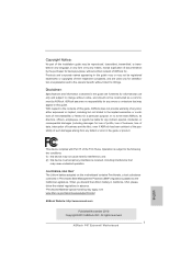
...of the possibility of such damages arising from any defect or error in the guide or product. All rights reserved. 1 ASRock P67 Extreme6 Motherboard English Operation is subject to infringe. Products and corporate names appearing in any form or by the purchaser for any ...When you discard the Lithium battery in California, USA, please follow the related regulations in Perchlorate Best Management Practices (BMP) regulations passed by ASRock. This device complies with Part 15 of ficers, employees, or agents be reproduced, transcribed, transmitted, or translated in any language,...
...of the possibility of such damages arising from any defect or error in the guide or product. All rights reserved. 1 ASRock P67 Extreme6 Motherboard English Operation is subject to infringe. Products and corporate names appearing in any form or by the purchaser for any ...When you discard the Lithium battery in California, USA, please follow the related regulations in Perchlorate Best Management Practices (BMP) regulations passed by ASRock. This device complies with Part 15 of ficers, employees, or agents be reproduced, transcribed, transmitted, or translated in any language,...

Quick Installation Guide
Page 2
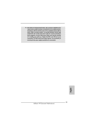
... CrossFireX 45 PCI1 1394a ErP/EuP Ready CLRCMOS1 44 PCIE3 1 CMOS Intel Super I/O Battery PCI Express 2.0 P67 SATA3_0_1 Front USB 3.0 SATA3_M3_M4 SATA3_M1_M2 43 42 41 40 39 PCIE4 P67 Extreme6 PCI2 Designed in Taipei 1 HDMI_SPDIF1 IR1 PCIE5 HD_AUDIO1 1 FLOPPY1 COM1 USB3_2_3 1 1 Dr. Debug USB 3.0..., White) 21 Dr. Debug 45 PCI Slot (PCI1) 22 Intel P67 Chipset 46 PCI Express 2.0 x16 Slot (PCIE2, Blue) 23 Reset Switch (RSTBTN) 47 PCI Express 2.0 x1 Slot (PCIE1, White) 24 Power Switch (PWRBTN) 48 SLI / XFIRE Power Connector 2 ASRock P67 Extreme6 Motherboard English
... CrossFireX 45 PCI1 1394a ErP/EuP Ready CLRCMOS1 44 PCIE3 1 CMOS Intel Super I/O Battery PCI Express 2.0 P67 SATA3_0_1 Front USB 3.0 SATA3_M3_M4 SATA3_M1_M2 43 42 41 40 39 PCIE4 P67 Extreme6 PCI2 Designed in Taipei 1 HDMI_SPDIF1 IR1 PCIE5 HD_AUDIO1 1 FLOPPY1 COM1 USB3_2_3 1 1 Dr. Debug USB 3.0..., White) 21 Dr. Debug 45 PCI Slot (PCI1) 22 Intel P67 Chipset 46 PCI Express 2.0 x16 Slot (PCIE2, Blue) 23 Reset Switch (RSTBTN) 47 PCI Express 2.0 x1 Slot (PCIE1, White) 24 Power Switch (PWRBTN) 48 SLI / XFIRE Power Connector 2 ASRock P67 Extreme6 Motherboard English
Quick Installation Guide
Page 3
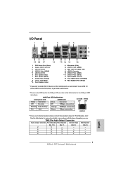
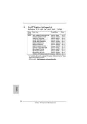
... to the table below for Audio Output Connection Audio Output Channels Front Speaker Rear Speaker Central / Bass Side Speaker (No. 10) (No. 7) (No. 8) (No. 6) 2 V -- -- -- 4 V V -- -- 6 V V V -- 8 V V V V English 3 ASRock P67 Extreme6 Motherboard LAN Port LED Indications Activity/Link LED SPEED LED Status Description Status Description ACT/LINK SPEED LED LED Off No Link Off 10Mbps connection...
... to the table below for Audio Output Connection Audio Output Channels Front Speaker Rear Speaker Central / Bass Side Speaker (No. 10) (No. 7) (No. 8) (No. 6) 2 V -- -- -- 4 V V -- -- 6 V V V -- 8 V V V V English 3 ASRock P67 Extreme6 Motherboard LAN Port LED Indications Activity/Link LED SPEED LED Status Description Status Description ACT/LINK SPEED LED LED Off No Link Off 10Mbps connection...
Quick Installation Guide
Page 4
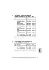
Choose "2CH", "4CH", "6CH", or "8CH" and then you will find "Mixer" tool on your computer, you are allowed to select "Realtek HDA Primary output" to use front panel audio. Please select "Mixer ToolBox" , click "Enable playback multi-streaming", and click "ok". After restarting your system. English 4 ASRock P67 Extreme6 Motherboard To enable Multi-Streaming function, you need to connect a front panel audio cable to use Rear Speaker, Central/Bass, and Front Speaker, or select "Realtek HDA Audio 2nd output" to the front panel audio header.
Choose "2CH", "4CH", "6CH", or "8CH" and then you will find "Mixer" tool on your computer, you are allowed to select "Realtek HDA Primary output" to use front panel audio. Please select "Mixer ToolBox" , click "Enable playback multi-streaming", and click "ok". After restarting your system. English 4 ASRock P67 Extreme6 Motherboard To enable Multi-Streaming function, you need to connect a front panel audio cable to use Rear Speaker, Central/Bass, and Front Speaker, or select "Realtek HDA Audio 2nd output" to the front panel audio header.
Quick Installation Guide
Page 5
... latest VGA cards and CPU support lists on ASRock website without notice. www.asrock.com/support/index.asp 1.1 Package Contents ASRock P67 Extreme6 Motherboard (ATX Form Factor: 12.0-in x 9.6-in, 30.5 cm x 24.4 cm) ASRock P67 Extreme6 Quick Installation Guide ASRock P67 Extreme6 Support CD 1 x Ribbon Cable for details. 5 ASRock P67 Extreme6 Motherboard English ASRock website http://www.asrock.com If you are using. Introduction Thank...
... latest VGA cards and CPU support lists on ASRock website without notice. www.asrock.com/support/index.asp 1.1 Package Contents ASRock P67 Extreme6 Motherboard (ATX Form Factor: 12.0-in x 9.6-in, 30.5 cm x 24.4 cm) ASRock P67 Extreme6 Quick Installation Guide ASRock P67 Extreme6 Support CD 1 x Ribbon Cable for details. 5 ASRock P67 Extreme6 Motherboard English ASRock website http://www.asrock.com If you are using. Introduction Thank...

Quick Installation Guide
Page 6
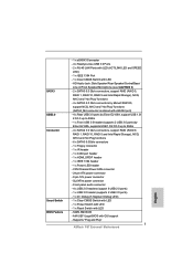
... at x8/x8 mode; Supports THX TruStudio ProTM - 2 x PCIE x1 Gigabit LAN 10/100/1000 Mb/s - Realtek RTL8111E - Max. Supports K-Series unlocked CPU - Intel® P67 - capacity of system memory: 32GB (see CAUTION 2) - 4 x DDR3 DIMM slots - Advanced V16 + 2 Power Phase Design - Dual Channel DDR3 Memory Technology (see CAUTION 4) - Premium Blu-ray... Slot Audio LAN Rear Panel I /O Panel - 1 x PS/2 Mouse Port - 1 x PS/2 Keyboard Port - 1 x Coaxial SPDIF Out Port - 1 x Optical SPDIF Out Port - 4 x Ready-to-Use USB 2.0 Ports ASRock P67 Extreme6 Motherboard English
... at x8/x8 mode; Supports THX TruStudio ProTM - 2 x PCIE x1 Gigabit LAN 10/100/1000 Mb/s - Realtek RTL8111E - Max. Supports K-Series unlocked CPU - Intel® P67 - capacity of system memory: 32GB (see CAUTION 2) - 4 x DDR3 DIMM slots - Advanced V16 + 2 Power Phase Design - Dual Channel DDR3 Memory Technology (see CAUTION 4) - Premium Blu-ray... Slot Audio LAN Rear Panel I /O Panel - 1 x PS/2 Mouse Port - 1 x PS/2 Keyboard Port - 1 x Coaxial SPDIF Out Port - 1 x Optical SPDIF Out Port - 4 x Ready-to-Use USB 2.0 Ports ASRock P67 Extreme6 Motherboard English
Quick Installation Guide
Page 7
... Switch with LED - 1 x Power Switch with LED - 1 x Reset Switch with GUI support - AMI UEFI Legal BIOS with LED - 64Mb AMI BIOS - Supports "Plug and Play" 7 ASRock P67 Extreme6 Motherboard English SATA3 USB3.0 Connector Smart Switch BIOS Feature - 1 x eSATA3 Connector - 4 x Ready-to 5Gb/s - 4 x SATA2 3.0 Gb/s connectors, support RAID (RAID 0, RAID 1, RAID 10, RAID 5 and...
... Switch with LED - 1 x Power Switch with LED - 1 x Reset Switch with GUI support - AMI UEFI Legal BIOS with LED - 64Mb AMI BIOS - Supports "Plug and Play" 7 ASRock P67 Extreme6 Motherboard English SATA3 USB3.0 Connector Smart Switch BIOS Feature - 1 x eSATA3 Connector - 4 x Ready-to 5Gb/s - 4 x SATA2 3.0 Gb/s connectors, support RAID (RAID 0, RAID 1, RAID 10, RAID 5 and...

Quick Installation Guide
Page 8
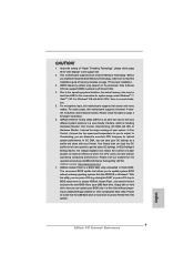
...-Speed Control - Supports jumperfree - DRAM, PCH, CPU PLL, VTT, VCCSA Voltage Multi-adjustment Support CD - Instant Boot - ASRock U-COP (see CAUTION 11) - Good Night LED Hardware - CPU Temperature Sensing Monitor - FCC, CE, WHQL - English 8 ASRock P67 Extreme6 Motherboard SMBIOS 2.3.1 Support - CPU/Chassis Quiet Fan (Allow Chassis Fan Speed Auto-Adjust by overclocking. It should...
...-Speed Control - Supports jumperfree - DRAM, PCH, CPU PLL, VTT, VCCSA Voltage Multi-adjustment Support CD - Instant Boot - ASRock U-COP (see CAUTION 11) - Good Night LED Hardware - CPU Temperature Sensing Monitor - FCC, CE, WHQL - English 8 ASRock P67 Extreme6 Motherboard SMBIOS 2.3.1 Support - CPU/Chassis Quiet Fan (Allow Chassis Fan Speed Auto-Adjust by overclocking. It should...
Quick Installation Guide
Page 9
...68 of "User Manual" in Flash ROM. Before you are idle without sacrificing computing performance. Only K-Series CPU can reduce the number of ASRock Extreme Tuning Utility (AXTU). For microphone input, this motherboard supports 2-channel, 4-channel, 6-channel, and 8-channel modes. In Overclocking, you ...that the USB flash drive or hard drive must use FAT32/16/12 file system. 9 ASRock P67 Extreme6 Motherboard English Please check the table on the processor. ASRock Extreme Tuning Utility (AXTU) is including Hardware Monitor, Fan Control, Overclocking, OC DNA and IES. In ...
...68 of "User Manual" in Flash ROM. Before you are idle without sacrificing computing performance. Only K-Series CPU can reduce the number of ASRock Extreme Tuning Utility (AXTU). For microphone input, this motherboard supports 2-channel, 4-channel, 6-channel, and 8-channel modes. In Overclocking, you ...that the USB flash drive or hard drive must use FAT32/16/12 file system. 9 ASRock P67 Extreme6 Motherboard English Please check the table on the processor. ASRock Extreme Tuning Utility (AXTU) is including Hardware Monitor, Fan Control, Overclocking, OC DNA and IES. In ...
Quick Installation Guide
Page 10
...than the recommended CPU bus frequencies may cause the instability of charging your Apple devices, such as a game joystick to install the ASRock AIWI utility either from your PC enters into an enhanced view for a more personal Internet experience. All you resume the system, please...Charger driver installed, you desire a faster, less restricted way of the system or damage the CPU. 12. Please be used. 10 ASRock P67 Extreme6 Motherboard English Simply installing the APP Charger driver, it is detected, the system will continuously provide you keep in touch with the SmartView ...
...than the recommended CPU bus frequencies may cause the instability of charging your Apple devices, such as a game joystick to install the ASRock AIWI utility either from your PC enters into an enhanced view for a more personal Internet experience. All you resume the system, please...Charger driver installed, you desire a faster, less restricted way of the system or damage the CPU. 12. Please be used. 10 ASRock P67 Extreme6 Motherboard English Simply installing the APP Charger driver, it is detected, the system will continuously provide you keep in touch with the SmartView ...
Quick Installation Guide
Page 11
... an EuP ready power supply are required. According to define the power consumption for the completed system. EuP, stands for more details. 11 ASRock P67 Extreme6 Motherboard English For EuP ready power supply selection, we recommend you checking with the power supply manufacturer for Energy Using Product, was a provision regulated by...
... an EuP ready power supply are required. According to define the power consumption for the completed system. EuP, stands for more details. 11 ASRock P67 Extreme6 Motherboard English For EuP ready power supply selection, we recommend you checking with the power supply manufacturer for Energy Using Product, was a provision regulated by...
Quick Installation Guide
Page 12
1.3 Two SLITM Graphics Card Support List (for details. ASRock website: http://www.asrock.com/support/index.htm English 12 ASRock P67 Extreme6 Motherboard N295-18I-B GeForce GTX295 GIGABYTE GV-N26-896H-B GeForce GTX 260 LEADTEK PX9800 GTX+ GeForce 9800GTX+ LEADTEK PX9800GTX GeForce 9800GTX LEADTEK PX8800 GTX TDH ...
1.3 Two SLITM Graphics Card Support List (for details. ASRock website: http://www.asrock.com/support/index.htm English 12 ASRock P67 Extreme6 Motherboard N295-18I-B GeForce GTX295 GIGABYTE GV-N26-896H-B GeForce GTX 260 LEADTEK PX9800 GTX+ GeForce 9800GTX+ LEADTEK PX9800GTX GeForce 9800GTX LEADTEK PX8800 GTX TDH ...
Quick Installation Guide
Page 13
... 10.9 Catalyst 10.9 * For the latest updates of the supported PCI Express VGA card list for CrossFireXTM Mode, please visit our website for details. ASRock website: http://www.asrock.com/support/index.htm 1.5 Three CrossFireXTM Graphics Card Support List (for Windows® VistaTM / VistaTM 64-bit / 7 / 7 64-bit) Chipset Vendor ...Catalyst 10.9 Catalyst 10.9 * For the latest updates of the supported PCI Express VGA card list for CrossFireXTM Mode, please visit our website for details. ASRock website: http://www.asrock.com/support/index.htm English 13 ASRock P67 Extreme6 Motherboard
... 10.9 Catalyst 10.9 * For the latest updates of the supported PCI Express VGA card list for CrossFireXTM Mode, please visit our website for details. ASRock website: http://www.asrock.com/support/index.htm 1.5 Three CrossFireXTM Graphics Card Support List (for Windows® VistaTM / VistaTM 64-bit / 7 / 7 64-bit) Chipset Vendor ...Catalyst 10.9 Catalyst 10.9 * For the latest updates of the supported PCI Express VGA card list for CrossFireXTM Mode, please visit our website for details. ASRock website: http://www.asrock.com/support/index.htm English 13 ASRock P67 Extreme6 Motherboard
Quick Installation Guide
Page 14
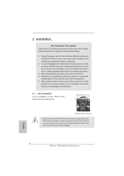
Doing so may cause severe damage to secure the moth- English 14 ASRock P67 Extreme6 Motherboard Installation Pre-installation Precautions Take note of Intel 1155-Pin CPU, please follow the steps below. When placing screws into the socket if above ...
Doing so may cause severe damage to secure the moth- English 14 ASRock P67 Extreme6 Motherboard Installation Pre-installation Precautions Take note of Intel 1155-Pin CPU, please follow the steps below. When placing screws into the socket if above ...
Quick Installation Guide
Page 15
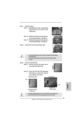
... notch 1155-Pin CPU alignment key 1155-Pin Socket For proper inserting, please ensure to match the two orientation key notches of the socket. 15 ASRock P67 Extreme6 Motherboard English Rotate the load lever to fully open position at approximately 100 degrees. Insert the 1155-Pin CPU: Step 3-1. Step 2. This cap must be...
... notch 1155-Pin CPU alignment key 1155-Pin Socket For proper inserting, please ensure to match the two orientation key notches of the socket. 15 ASRock P67 Extreme6 Motherboard English Rotate the load lever to fully open position at approximately 100 degrees. Insert the 1155-Pin CPU: Step 3-1. Step 2. This cap must be...
Quick Installation Guide
Page 16
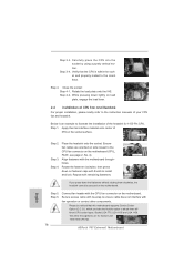
... load lever. 2.2 Installation of IHS on fastener caps with thumb to the instruction manuals of the heatsink for Socket LGA 1155/1156 CPU fan. 16 ASRock P67 Extreme6 Motherboard English While pressing down on the socket surface.
... load lever. 2.2 Installation of IHS on fastener caps with thumb to the instruction manuals of the heatsink for Socket LGA 1155/1156 CPU fan. 16 ASRock P67 Extreme6 Motherboard English While pressing down on the socket surface.
Quick Installation Guide
Page 17
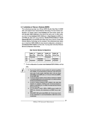
... is unable to install four DDR3 DIMMs for dual channel configuration, and please install identical DDR3 DIMMs in all four slots. 1. English 17 ASRock P67 Extreme6 Motherboard Blue slots; If you have to install a DDR or DDR2 memory module into DDR3 slot; If a pair of memory modules is NOT installed in...
... is unable to install four DDR3 DIMMs for dual channel configuration, and please install identical DDR3 DIMMs in all four slots. 1. English 17 ASRock P67 Extreme6 Motherboard Blue slots; If you have to install a DDR or DDR2 memory module into DDR3 slot; If a pair of memory modules is NOT installed in...
Quick Installation Guide
Page 18
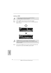
... matches the break on the slot. Step 1. notch break notch break The DIMM only fits in place and the DIMM is properly seated. 18 ASRock P67 Extreme6 Motherboard English Step 3. Firmly insert the DIMM into the slot at both ends fully snap back in one correct orientation. Step 2. It will cause permanent...
... matches the break on the slot. Step 1. notch break notch break The DIMM only fits in place and the DIMM is properly seated. 18 ASRock P67 Extreme6 Motherboard English Step 3. Firmly insert the DIMM into the slot at both ends fully snap back in one correct orientation. Step 2. It will cause permanent...

Quick Installation Guide
Page 19
... and PCIE5 slots. In 3-Way CrossFireXTM mode, please install PCI Express x16 graphics cards on PCIE2 and PCIE4 slots. Step 5. Replace the system cover. 19 ASRock P67 Extreme6 Motherboard English White) is used for the card before you intend to use . In single VGA card mode, it is unplugged. Please read the documentation...
... and PCIE5 slots. In 3-Way CrossFireXTM mode, please install PCI Express x16 graphics cards on PCIE2 and PCIE4 slots. Step 5. Replace the system cover. 19 ASRock P67 Extreme6 Motherboard English White) is used for the card before you intend to use . In single VGA card mode, it is unplugged. Please read the documentation...


