
Intel Rapid Storage Guide
Page 12
... Enter. 4. Enable RAID in the system BIOS. 1. Switch the SATA Operation Mode option to enable RAID in System BIOS Use the instructions included with your motherboard to RAID. 5. Click the Storage Configuration menu. 4. When finished press Enter. 12
... Enter. 4. Enable RAID in the system BIOS. 1. Switch the SATA Operation Mode option to enable RAID in System BIOS Use the instructions included with your motherboard to RAID. 5. Click the Storage Configuration menu. 4. When finished press Enter. 12

User Manual
Page 2
With respect to the contents of this motherboard contains Perchlorate, a toxic substance controlled in Perchlorate Best Management Practices (BMP) regulations passed by the California Legislature. CALIFORNIA, USA ONLY The Lithium battery adopted on this manual, ASRock does not provide warranty of any kind...;tness for a particular purpose. "Perchlorate Material-special handling may apply, see www.dtsc.ca.gov/hazardouswaste/perchlorate" ASRock Website: http://www.asrock.com 2 Disclaimer: Specifications and information contained in this manual are used only for identification or...
With respect to the contents of this motherboard contains Perchlorate, a toxic substance controlled in Perchlorate Best Management Practices (BMP) regulations passed by the California Legislature. CALIFORNIA, USA ONLY The Lithium battery adopted on this manual, ASRock does not provide warranty of any kind...;tness for a particular purpose. "Perchlorate Material-special handling may apply, see www.dtsc.ca.gov/hazardouswaste/perchlorate" ASRock Website: http://www.asrock.com 2 Disclaimer: Specifications and information contained in this manual are used only for identification or...

User Manual
Page 3
Contents 1 Introduction 5 1.1 Package Contents 5 1.2 Specifications 6 1.3 Motherboard Layout 14 1.4 I/O Panel 15 2 Installation 17 2.1 Screw Holes 17 2.2 Pre-installation Precautions 17 2.3 CPU Installation 18 2.4 Installation of Heatsink and CPU fan 20 2.5 Installation of ...
Contents 1 Introduction 5 1.1 Package Contents 5 1.2 Specifications 6 1.3 Motherboard Layout 14 1.4 I/O Panel 15 2 Installation 17 2.1 Screw Holes 17 2.2 Pre-installation Precautions 17 2.3 CPU Installation 18 2.4 Installation of Heatsink and CPU fan 20 2.5 Installation of ...
User Manual
Page 5
... without notice. Chapter 1: Introduction Thank you for specific information about the model you require technical support related to this motherboard, please visit our website for purchasing ASRock P67 Extreme6 motherboard, a reliable motherboard produced under ASRock's consistently stringent quality control. In this manual will be subject to quality and endurance. In case any modifications of...
... without notice. Chapter 1: Introduction Thank you for specific information about the model you require technical support related to this motherboard, please visit our website for purchasing ASRock P67 Extreme6 motherboard, a reliable motherboard produced under ASRock's consistently stringent quality control. In this manual will be subject to quality and endurance. In case any modifications of...
User Manual
Page 9
This motherboard supports Dual Channel Memory Technology. Only K-Series CPU can save the new BIOS file to fine-tune different system functions in Flash ROM. Please check the table on page 21 for proper installation. 3. ASRock Extreme Tuning Utility (AXTU) is an all-in-one ...In OC DNA, you to access ASRock Instant Flash. Your friends then can press key during the POST or press key to BIOS setup menu to adjust. Please be less than 4GB for the reservation for optimal system performance. For microphone input, this motherboard supports 2-channel, 4-channel, 6-channel,...
This motherboard supports Dual Channel Memory Technology. Only K-Series CPU can save the new BIOS file to fine-tune different system functions in Flash ROM. Please check the table on page 21 for proper installation. 3. ASRock Extreme Tuning Utility (AXTU) is an all-in-one ...In OC DNA, you to access ASRock Instant Flash. Your friends then can press key during the POST or press key to BIOS setup menu to adjust. Please be less than 4GB for the reservation for optimal system performance. For microphone input, this motherboard supports 2-channel, 4-channel, 6-channel,...

User Manual
Page 10
... 7 64 bit / VistaTM / VistaTM 64 bit, and your iPhone/iPod touch. Although this motherboard offers stepless control, it is detected, the system will continuously provide you - Please be used. 10 ASRock AIWI utility introduces a new way of the system or damage the CPU. 12. While CPU ...IE8. To improve heat dissipation, remember to RAM (S3), hibernation mode (S4) or power off (S5). ASRock motherboards are exclusively equipped with friends on the motherboard functions properly and unplug the power cord, then plug it makes your iPhone charged much quickly from App store to...
... 7 64 bit / VistaTM / VistaTM 64 bit, and your iPhone/iPod touch. Although this motherboard offers stepless control, it is detected, the system will continuously provide you - Please be used. 10 ASRock AIWI utility introduces a new way of the system or damage the CPU. 12. While CPU ...IE8. To improve heat dissipation, remember to RAM (S3), hibernation mode (S4) or power off (S5). ASRock motherboards are exclusively equipped with friends on the motherboard functions properly and unplug the power cord, then plug it makes your iPhone charged much quickly from App store to...

User Manual
Page 11
According to Intel's suggestion, the EuP ready power supply must meet EuP standard, an EuP ready motherboard and an EuP ready power supply are required. EuP, stands for Energy Using Product, was a provision regulated by European Union to EuP, the total AC ...
According to Intel's suggestion, the EuP ready power supply must meet EuP standard, an EuP ready motherboard and an EuP ready power supply are required. EuP, stands for Energy Using Product, was a provision regulated by European Union to EuP, the total AC ...

User Manual
Page 14
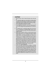
1.6 Motherboard Layout 1 2 24.4cm (9.6 in) 34 56 PS2 Mouse PS2...PCI1 1394a ErP/EuP Ready CLRCMOS1 44 PCIE3 1 CMOS Intel Super I/O Battery PCI Express 2.0 P67 SATA3_0_1 Front USB 3.0 SATA3_M3_M4 SATA3_M1_M2 43 42 41 40 39 PCIE4 P67 Extreme6 PCI2 Designed in Taipei 1 HDMI_SPDIF1 IR1 PCIE5 HD_AUDIO1 1 FLOPPY1 COM1 USB3_2_3 1 1 Dr. ... (SATA3_M1, White) 19 SATA3 Connector (SATA3_M4, White) 20 SATA3 Connector (SATA3_M3, White) 21 Dr. Debug 22 Intel P67 Chipset 23 Reset Switch (RSTBTN) 24 Power Switch (PWRBTN) 25 Power LED Header (PLED1) 26 Chassis Speaker Header (SPEAKER...
1.6 Motherboard Layout 1 2 24.4cm (9.6 in) 34 56 PS2 Mouse PS2...PCI1 1394a ErP/EuP Ready CLRCMOS1 44 PCIE3 1 CMOS Intel Super I/O Battery PCI Express 2.0 P67 SATA3_0_1 Front USB 3.0 SATA3_M3_M4 SATA3_M1_M2 43 42 41 40 39 PCIE4 P67 Extreme6 PCI2 Designed in Taipei 1 HDMI_SPDIF1 IR1 PCIE5 HD_AUDIO1 1 FLOPPY1 COM1 USB3_2_3 1 1 Dr. ... (SATA3_M1, White) 19 SATA3 Connector (SATA3_M4, White) 20 SATA3 Connector (SATA3_M3, White) 21 Dr. Debug 22 Intel P67 Chipset 23 Reset Switch (RSTBTN) 24 Power Switch (PWRBTN) 25 Power LED Header (PLED1) 26 Chassis Speaker Header (SPEAKER...

User Manual
Page 15
... (USB12) 17 Optical SPDIF Out Port 18 Clear CMOS Switch (CLRCBTN) 19 PS/2 Keyboard Port (Purple) * If you want to install USB 3.0 device on this motherboard, we recommend to use USB 3.0 ports (USB12) as the first priority to get better performance. * There are two LED next to the table below...
... (USB12) 17 Optical SPDIF Out Port 18 Clear CMOS Switch (CLRCBTN) 19 PS/2 Keyboard Port (Purple) * If you want to install USB 3.0 device on this motherboard, we recommend to use USB 3.0 ports (USB12) as the first priority to get better performance. * There are two LED next to the table below...

User Manual
Page 17
... switched off or the power cord is an ATX form factor (12.0" x 9.6", 30.5 x 24.4 cm) motherboard. Failure to unplug the power cord before you install motherboard components or change any component. 2. Chapter 2: Installation This is detached from the wall socket before you handle components.... Failure to do so may cause physical injuries to you install the motherboard, study the configuration of the following precautions before installing or removing the motherboard. Before you and damages to motherboard components. 2.1 Screw Holes Place screws into it on the carpet or...
... switched off or the power cord is an ATX form factor (12.0" x 9.6", 30.5 x 24.4 cm) motherboard. Failure to unplug the power cord before you install motherboard components or change any component. 2. Chapter 2: Installation This is detached from the wall socket before you handle components.... Failure to do so may cause physical injuries to you install the motherboard, study the configuration of the following precautions before installing or removing the motherboard. Before you and damages to motherboard components. 2.1 Screw Holes Place screws into it on the carpet or...

User Manual
Page 18
... is any bent pin on the hook to handle and avoid kicking off the PnP cap. 2. Otherwise, the CPU will be placed if returning the motherboard for after service. 18 Remove PnP Cap (Pick and Place Cap). 1. Step 1-3. This cap must be seriously damaged. Do not force to insert the CPU...
... is any bent pin on the hook to handle and avoid kicking off the PnP cap. 2. Otherwise, the CPU will be placed if returning the motherboard for after service. 18 Remove PnP Cap (Pick and Place Cap). 1. Step 1-3. This cap must be seriously damaged. Do not force to insert the CPU...

User Manual
Page 20
... not interfere with thumb to dissipate heat. Ensure fan cables are securely fastened and in good contact with 1155-Pin socket that this motherboard supports Combo Cooler Option (C.C.O.), which provides the flexible option to the CPU_FAN connector (CPU_FAN1, see page 14, No. 4). Rotate...three different CPU cooler types, Socket LGA 775, LGA 1155 and LGA 1156. Apply Thermal Interface Material Step 2. Repeat with the motherboard throughholes. Please adopt the type of heatsink and cooling fan compliant with tie-wrap to improve heat dissipation. Before you installed the...
... not interfere with thumb to dissipate heat. Ensure fan cables are securely fastened and in good contact with 1155-Pin socket that this motherboard supports Combo Cooler Option (C.C.O.), which provides the flexible option to the CPU_FAN connector (CPU_FAN1, see page 14, No. 4). Rotate...three different CPU cooler types, Socket LGA 775, LGA 1155 and LGA 1156. Apply Thermal Interface Material Step 2. Repeat with the motherboard throughholes. Please adopt the type of heatsink and cooling fan compliant with tie-wrap to improve heat dissipation. Before you installed the...

User Manual
Page 21
...Dual Channel Memory Technology . 4. In other words, install them in DDR3_A1 and DDR3_A2, it is not allowed to install them on this motherboard and DIMM may be activated. If only one memory module or three memory modules are installed in Dual Channel A (DDR3_ A1 and DDR3_B1;...to activate the Dual Channel Memory Technology. 3. see p.14 No.5) or identical DDR3 DIMM pair in the slots of Memory Modules (DIMM) This motherboard provides four 240-pin DDR3 (Double Data Rate 3) DIMM slots, and supports Dual Channel Memory Technology. Populated - If you to install identical (the...
...Dual Channel Memory Technology . 4. In other words, install them in DDR3_A1 and DDR3_A2, it is not allowed to install them on this motherboard and DIMM may be activated. If only one memory module or three memory modules are installed in Dual Channel A (DDR3_ A1 and DDR3_B1;...to activate the Dual Channel Memory Technology. 3. see p.14 No.5) or identical DDR3 DIMM pair in the slots of Memory Modules (DIMM) This motherboard provides four 240-pin DDR3 (Double Data Rate 3) DIMM slots, and supports Dual Channel Memory Technology. Populated - If you to install identical (the...

User Manual
Page 22
.... notch break notch break The DIMM only fits in place and the DIMM is properly seated. 22 Installing a DIMM Please make sure to the motherboard and the DIMM if you force the DIMM into the slot until the retaining clips at incorrect orientation. Step 1. Step 2.
.... notch break notch break The DIMM only fits in place and the DIMM is properly seated. 22 Installing a DIMM Please make sure to the motherboard and the DIMM if you force the DIMM into the slot until the retaining clips at incorrect orientation. Step 1. Step 2.

User Manual
Page 23
...card connector with screws. In single VGA card mode, it is unplugged. In 3-Way CrossFireXTM mode, please install PCI Express x16 graphics cards on this motherboard. Installing an expansion card Step 1. Step 2. Keep the screws for later use . PCIE slots: PCIE1 / PCIE3 (PCIE x1 slot; Blue) ... to install expansion cards that you first time install or remove PCI Express x1 card on the slot. Fasten the card to motherboard chassis fan connector (CHA_FAN1, CHA_FAN2 or CHA_FAN3) when using multiple graphics cards for the card before you start the installation. Replace the ...
...card connector with screws. In single VGA card mode, it is unplugged. In 3-Way CrossFireXTM mode, please install PCI Express x16 graphics cards on this motherboard. Installing an expansion card Step 1. Step 2. Keep the screws for later use . PCIE slots: PCIE1 / PCIE3 (PCIE x1 slot; Blue) ... to install expansion cards that you first time install or remove PCI Express x1 card on the slot. Fasten the card to motherboard chassis fan connector (CHA_FAN1, CHA_FAN2 or CHA_FAN3) when using multiple graphics cards for the card before you start the installation. Replace the ...

User Manual
Page 24
... up to the PCI Express graphics cards. 24 Download the driver from NVIDIA® website (www.nvidia.com). 3. 2.7 SLITM and Quad SLITM Operation Guide This motherboard supports NVIDIA® SLITM and Quad SLITM (Scalable Link Interface) technology that allows you should have two identical Quad SLITM-ready graphics cards that are...
... up to the PCI Express graphics cards. 24 Download the driver from NVIDIA® website (www.nvidia.com). 3. 2.7 SLITM and Quad SLITM Operation Guide This motherboard supports NVIDIA® SLITM and Quad SLITM (Scalable Link Interface) technology that allows you should have two identical Quad SLITM-ready graphics cards that are...

User Manual
Page 28
All three CrossFireXTM components, a CrossFireXTM Ready graphics card, a CrossFireXTM Ready motherboard and a CrossFireXTM Edition co-processor graphics card, must be installed correctly to PCIE4 slot. Step 1. Currently CrossFireXTM...methods to ATITM graphics card manuals for ATITM CrossFireXTM driver updates. 1. 2.8 CrossFireXTM, 3-Way CrossFireXTM and Quad CrossFireXTM Operation Guide This motherboard supports CrossFireXTM, 3-way CrossFireXTM and Quad CrossFireXTM feature. CrossFireXTM technology offers the most advantageous means available of combining multiple high performance Graphics ...
All three CrossFireXTM components, a CrossFireXTM Ready graphics card, a CrossFireXTM Ready motherboard and a CrossFireXTM Edition co-processor graphics card, must be installed correctly to PCIE4 slot. Step 1. Currently CrossFireXTM...methods to ATITM graphics card manuals for ATITM CrossFireXTM driver updates. 1. 2.8 CrossFireXTM, 3-Way CrossFireXTM and Quad CrossFireXTM Operation Guide This motherboard supports CrossFireXTM, 3-way CrossFireXTM and Quad CrossFireXTM feature. CrossFireXTM technology offers the most advantageous means available of combining multiple high performance Graphics ...

User Manual
Page 29
... the Radeon graphics card on the top of Radeon graphics cards. (CrossFire Bridge is provided with the graphics card you purchase, not bundled with this motherboard. Step 2. Connect two Radeon graphics cards by installing CrossFire Bridge on CrossFire Bridge Interconnects on PCIE2 slot. (You may use the DVI to D-Sub adapter...
... the Radeon graphics card on the top of Radeon graphics cards. (CrossFire Bridge is provided with the graphics card you purchase, not bundled with this motherboard. Step 2. Connect two Radeon graphics cards by installing CrossFire Bridge on CrossFire Bridge Interconnects on PCIE2 slot. (You may use the DVI to D-Sub adapter...

User Manual
Page 30
... card to connect Radeon graphics cards on PCIE4 and PCIE5 slots. (CrossFireTM Bridge is provided with the graphics card you purchase, not bundled with this motherboard. Step 2. Please refer to section "Expansion Slots". Install one Radeon graphics card to PCIE5 slot. For the proper installation procedures, please refer to your graphics...
... card to connect Radeon graphics cards on PCIE4 and PCIE5 slots. (CrossFireTM Bridge is provided with the graphics card you purchase, not bundled with this motherboard. Step 2. Please refer to section "Expansion Slots". Install one Radeon graphics card to PCIE5 slot. For the proper installation procedures, please refer to your graphics...

User Manual
Page 33
... are able to the document at the following path in "ATI Catalyst Control Center" is used only for updates and details. 2.9 Surround Display Feature This motherboard supports Surround Display upgrade. After restarting your computer, please confirm whether the option "Enable CrossFireTM" in the Support CD: ..\ Surround Display Information 33...
... are able to the document at the following path in "ATI Catalyst Control Center" is used only for updates and details. 2.9 Surround Display Feature This motherboard supports Surround Display upgrade. After restarting your computer, please confirm whether the option "Enable CrossFireTM" in the Support CD: ..\ Surround Display Information 33...


