User Manual
Page 5
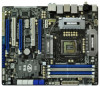
... CPU support lists on ASRock website without notice. www.asrock.com/support/index.asp 1.1 Package Contents ASRock P67 Extreme6 Motherboard (ATX Form Factor: 12.0-in x 9.6-in, 30.5 cm x 24.4 cm) ASRock P67 Extreme6 Quick Installation Guide ASRock P67 Extreme6 Support CD 1 x Ribbon Cable for a 3.5-in our support CD for purchasing ASRock P67 Extreme6 motherboard, a reliable motherboard produced under ASRock's consistently stringent quality control. ASRock website http://www.asrock.com If you...
... CPU support lists on ASRock website without notice. www.asrock.com/support/index.asp 1.1 Package Contents ASRock P67 Extreme6 Motherboard (ATX Form Factor: 12.0-in x 9.6-in, 30.5 cm x 24.4 cm) ASRock P67 Extreme6 Quick Installation Guide ASRock P67 Extreme6 Support CD 1 x Ribbon Cable for a 3.5-in our support CD for purchasing ASRock P67 Extreme6 motherboard, a reliable motherboard produced under ASRock's consistently stringent quality control. ASRock website http://www.asrock.com If you...

User Manual
Page 14
1.6 Motherboard Layout 1 2 24.4cm (9.6 in) 34 ... ErP/EuP Ready CLRCMOS1 44 PCIE3 1 CMOS Intel Super I/O Battery PCI Express 2.0 P67 SATA3_0_1 Front USB 3.0 SATA3_M3_M4 SATA3_M1_M2 43 42 41 40 39 PCIE4 P67 Extreme6 PCI2 Designed in Taipei 1 HDMI_SPDIF1 IR1 PCIE5 HD_AUDIO1 1 FLOPPY1 COM1 USB3_2_3 1 1 ...DIMM Slots (Dual Channel: DDR3_A1, DDR3_B1, Blue) 6 2 x 240-pin DDR3 DIMM Slots (Dual Channel: DDR3_A2, DDR3_B2, White) 7 ATX Power Connector (ATXPWR1) 8 Front Panel IEEE 1394 Header (FRONT_1394, White) 9 Power Fan Connector (PWR_FAN1) 10 Chassis Fan Connector (CHA_FAN3) 11...
1.6 Motherboard Layout 1 2 24.4cm (9.6 in) 34 ... ErP/EuP Ready CLRCMOS1 44 PCIE3 1 CMOS Intel Super I/O Battery PCI Express 2.0 P67 SATA3_0_1 Front USB 3.0 SATA3_M3_M4 SATA3_M1_M2 43 42 41 40 39 PCIE4 P67 Extreme6 PCI2 Designed in Taipei 1 HDMI_SPDIF1 IR1 PCIE5 HD_AUDIO1 1 FLOPPY1 COM1 USB3_2_3 1 1 ...DIMM Slots (Dual Channel: DDR3_A1, DDR3_B1, Blue) 6 2 x 240-pin DDR3 DIMM Slots (Dual Channel: DDR3_A2, DDR3_B2, White) 7 ATX Power Connector (ATXPWR1) 8 Front Panel IEEE 1394 Header (FRONT_1394, White) 9 Power Fan Connector (PWR_FAN1) 10 Chassis Fan Connector (CHA_FAN3) 11...

User Manual
Page 17
Doing so may damage the motherboard. 2.2 Pre-installation Precautions Take note of your motherboard directly on a grounded antistatic pad or in the bag that the power is switched off or the power cord is an ATX form factor (12.0" x 9.6", 30.5 x 24.4 cm) motherboard. Also remember to use a grounded... wrist strap or touch a safety grounded object before you install the motherboard, study the configuration of the following precautions before...
Doing so may damage the motherboard. 2.2 Pre-installation Precautions Take note of your motherboard directly on a grounded antistatic pad or in the bag that the power is switched off or the power cord is an ATX form factor (12.0" x 9.6", 30.5 x 24.4 cm) motherboard. Also remember to use a grounded... wrist strap or touch a safety grounded object before you install the motherboard, study the configuration of the following precautions before...

User Manual
Page 39
...Power Connector (4-pin SLI/XFIRE_PWR1) (see p.14 No. 1) 8 5 4 1 Please connect an ATX 12V power supply to this motherboard provides 24-pin ATX power connector, 12 24 it can still work if you adopt a traditional 20-pin ATX power supply. Pin 1-3 Connected (3-pin CPU_FAN2) (see p.14 No. 3) 3-Pin Fan Installation...Pin CPU fan still can work successfully even without the fan speed control function. Though this motherboard provides 8-pin ATX 12V power connector, it can still work if you adopt a traditional 4-pin ATX 12V power supply. If you plan to connect the 3-Pin CPU fan to the CPU...
...Power Connector (4-pin SLI/XFIRE_PWR1) (see p.14 No. 1) 8 5 4 1 Please connect an ATX 12V power supply to this motherboard provides 24-pin ATX power connector, 12 24 it can still work if you adopt a traditional 20-pin ATX power supply. Pin 1-3 Connected (3-pin CPU_FAN2) (see p.14 No. 3) 3-Pin Fan Installation...Pin CPU fan still can work successfully even without the fan speed control function. Though this motherboard provides 8-pin ATX 12V power connector, it can still work if you adopt a traditional 4-pin ATX 12V power supply. If you plan to connect the 3-Pin CPU fan to the CPU...

Quick Installation Guide
Page 2
...2 x 240-pin DDR3 DIMM Slots 30 USB 2.0 Header (USB12_13, Blue) (Dual Channel: DDR3_A2, DDR3_B2, White) 31 USB 2.0 Header (USB10_11, Blue) 7 ATX Power Connector (ATXPWR1) 32 Clear CMOS Jumper (CLRCMOS1) 8 Front Panel IEEE 1394 Header 33 USB 2.0 Header (USB8_9, Blue) (FRONT_1394, White) 34 USB 2.0 ... x1 Slot (PCIE3, White) 21 Dr. Debug 45 PCI Slot (PCI1) 22 Intel P67 Chipset 46 PCI Express 2.0 x16 Slot (PCIE2, Blue) 23 Reset Switch (RSTBTN) 47 PCI Express 2.0 x1 Slot (PCIE1, White) 24 Power Switch (PWRBTN) 48 SLI / XFIRE Power Connector 2 ASRock P67 Extreme6 Motherboard English
...2 x 240-pin DDR3 DIMM Slots 30 USB 2.0 Header (USB12_13, Blue) (Dual Channel: DDR3_A2, DDR3_B2, White) 31 USB 2.0 Header (USB10_11, Blue) 7 ATX Power Connector (ATXPWR1) 32 Clear CMOS Jumper (CLRCMOS1) 8 Front Panel IEEE 1394 Header 33 USB 2.0 Header (USB8_9, Blue) (FRONT_1394, White) 34 USB 2.0 ... x1 Slot (PCIE3, White) 21 Dr. Debug 45 PCI Slot (PCI1) 22 Intel P67 Chipset 46 PCI Express 2.0 x16 Slot (PCIE2, Blue) 23 Reset Switch (RSTBTN) 47 PCI Express 2.0 x1 Slot (PCIE1, White) 24 Power Switch (PWRBTN) 48 SLI / XFIRE Power Connector 2 ASRock P67 Extreme6 Motherboard English
Quick Installation Guide
Page 5
.../support/index.asp 1.1 Package Contents ASRock P67 Extreme6 Motherboard (ATX Form Factor: 12.0-in x 9.6-in, 30.5 cm x 24.4 cm) ASRock P67 Extreme6 Quick Installation Guide ASRock P67 Extreme6 Support CD 1 x Ribbon Cable for purchasing ASRock P67 Extreme6 motherboard, a reliable motherboard produced under ASRock's consistently stringent quality control. This Quick Installation Guide contains introduction of this manual will be available on ASRock website as well. You may find...
.../support/index.asp 1.1 Package Contents ASRock P67 Extreme6 Motherboard (ATX Form Factor: 12.0-in x 9.6-in, 30.5 cm x 24.4 cm) ASRock P67 Extreme6 Quick Installation Guide ASRock P67 Extreme6 Support CD 1 x Ribbon Cable for purchasing ASRock P67 Extreme6 motherboard, a reliable motherboard produced under ASRock's consistently stringent quality control. This Quick Installation Guide contains introduction of this manual will be available on ASRock website as well. You may find...

Quick Installation Guide
Page 6
...Supports LAN Cable Detection - Supports Intel® Turbo Boost 2.0 Technology - Supports K-Series unlocked CPU - Intel® P67 - Supports NVIDIA® Quad SLITM and SLITM - 7.1 CH HD Audio with Teaming function I /O 6 - Max.... 32GB (see CAUTION 2) - 4 x DDR3 DIMM slots - Supports Dual LAN with Content Protection (Realtek ALC892 Audio Codec) - ATX Form Factor: 12.0-in x 9.6-in LGA1155 Package - Supports 2nd Generation Intel® CoreTM i7 / i5 / i3 in , 30... Out Port - 1 x Optical SPDIF Out Port - 4 x Ready-to-Use USB 2.0 Ports ASRock P67 Extreme6 Motherboard English
...Supports LAN Cable Detection - Supports Intel® Turbo Boost 2.0 Technology - Supports K-Series unlocked CPU - Intel® P67 - Supports NVIDIA® Quad SLITM and SLITM - 7.1 CH HD Audio with Teaming function I /O 6 - Max.... 32GB (see CAUTION 2) - 4 x DDR3 DIMM slots - Supports Dual LAN with Content Protection (Realtek ALC892 Audio Codec) - ATX Form Factor: 12.0-in x 9.6-in LGA1155 Package - Supports 2nd Generation Intel® CoreTM i7 / i5 / i3 in , 30... Out Port - 1 x Optical SPDIF Out Port - 4 x Ready-to-Use USB 2.0 Ports ASRock P67 Extreme6 Motherboard English
Quick Installation Guide
Page 7
... CMOS Switch with LED - 1 x Power Switch with LED - 1 x Reset Switch with GUI support - CPU/Chassis/Power FAN connector - 24 pin ATX power connector - 8 pin 12V power connector - Supports "Plug and Play" 7 ASRock P67 Extreme6 Motherboard English SLI/XFire power connector - AMI UEFI Legal BIOS with LED - 64Mb AMI BIOS - HD Audio Jack: Side Speaker/Rear...
... CMOS Switch with LED - 1 x Power Switch with LED - 1 x Reset Switch with GUI support - CPU/Chassis/Power FAN connector - 24 pin ATX power connector - 8 pin 12V power connector - Supports "Plug and Play" 7 ASRock P67 Extreme6 Motherboard English SLI/XFire power connector - AMI UEFI Legal BIOS with LED - 64Mb AMI BIOS - HD Audio Jack: Side Speaker/Rear...

Quick Installation Guide
Page 35
... (see p.2 No. 7) 12 24 Please connect an ATX power supply to this connector. 1 13 Though this motherboard provides 24-pin ATX power connector, 12 24 it with Pin 1 and Pin 13. 20-Pin ATX Power Supply Installation 1 13 ATX 12V Power Connector (8-pin ATX12V1) (see p.2 No. 48...motherboard provides 4-Pin CPU fan (Quiet Fan) support, the 3-Pin CPU fan still can work if you adopt a traditional 4-pin ATX 12V power supply. To use this connector, but please connect it can still work successfully even without the fan speed control function. English 35 ASRock P67 Extreme6 Motherboard...
... (see p.2 No. 7) 12 24 Please connect an ATX power supply to this connector. 1 13 Though this motherboard provides 24-pin ATX power connector, 12 24 it with Pin 1 and Pin 13. 20-Pin ATX Power Supply Installation 1 13 ATX 12V Power Connector (8-pin ATX12V1) (see p.2 No. 48...motherboard provides 4-Pin CPU fan (Quiet Fan) support, the 3-Pin CPU fan still can work if you adopt a traditional 4-pin ATX 12V power supply. To use this connector, but please connect it can still work successfully even without the fan speed control function. English 35 ASRock P67 Extreme6 Motherboard...
Quick Installation Guide
Page 214
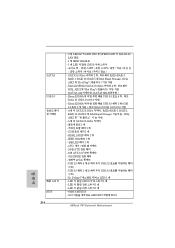
...; SPEED LED RJ-45 LAN 포트 - 1 개 IEEE 1394 포트 - 1 개 LED 가 달린 CMOS 5 참조 ) - LED 1 개 - CPU 24 핀 ATX 8 핀 ATX 12V SLI/XFIRE USB 2.0 헤더 4 개 (8 USB 2.0 2개 ) - GUI AMI UEFI 적합형 BIOS ASRock P67 Extreme6 Motherboard
...; SPEED LED RJ-45 LAN 포트 - 1 개 IEEE 1394 포트 - 1 개 LED 가 달린 CMOS 5 참조 ) - LED 1 개 - CPU 24 핀 ATX 8 핀 ATX 12V SLI/XFIRE USB 2.0 헤더 4 개 (8 USB 2.0 2개 ) - GUI AMI UEFI 적합형 BIOS ASRock P67 Extreme6 Motherboard

Quick Installation Guide
Page 231
...; CPU CPU 3 핀 CPU 1-3 1-3 3 (3 핀 CPU_FAN2) (2 3 ATX (24 핀 ATXPWR1) (2 7 12 24 ATX 1 13 24 핀 ATX 12 24 종래의 20 핀 ATX 20 핀 ATX Pin 1 과 Pin 13 20 핀 ATX 1 13 ATX 12V (8 핀 ATX12V1) (2 1 8 5 4 1 ATX 12V 8- 핀 ATX 12V 4- 핀 ATX 12V 용하여 4- 핀 ATX 1 과 핀 5 8 5 4- 핀 ATX 12V 4 1 한국어 231 ASRock P67 Extreme6 Motherboard
...; CPU CPU 3 핀 CPU 1-3 1-3 3 (3 핀 CPU_FAN2) (2 3 ATX (24 핀 ATXPWR1) (2 7 12 24 ATX 1 13 24 핀 ATX 12 24 종래의 20 핀 ATX 20 핀 ATX Pin 1 과 Pin 13 20 핀 ATX 1 13 ATX 12V (8 핀 ATX12V1) (2 1 8 5 4 1 ATX 12V 8- 핀 ATX 12V 4- 핀 ATX 12V 용하여 4- 핀 ATX 1 과 핀 5 8 5 4- 핀 ATX 12V 4 1 한국어 231 ASRock P67 Extreme6 Motherboard
Quick Installation Guide
Page 239
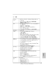
...) - Premium Blu-ray THX TruStudio ProTM 2 x PCIE x1 Gigabit LAN 10/100/1000 Mb/s - PS/2 x 1 - PS/2 x 1 - 同軸 SPDIF x 1 - 光学 SPDIF x 1 239 ASRock P67 Extreme6 Motherboard 日本語 ATX 12.0-in x 9.6-in, 30.5 cm x 24.4 cm 100 - 第 2 世代の Intel® CoreTM i7 / i5 / i3 in LGA1155 - 高度な V16...
...) - Premium Blu-ray THX TruStudio ProTM 2 x PCIE x1 Gigabit LAN 10/100/1000 Mb/s - PS/2 x 1 - PS/2 x 1 - 同軸 SPDIF x 1 - 光学 SPDIF x 1 239 ASRock P67 Extreme6 Motherboard 日本語 ATX 12.0-in x 9.6-in, 30.5 cm x 24.4 cm 100 - 第 2 世代の Intel® CoreTM i7 / i5 / i3 in LGA1155 - 高度な V16...

Quick Installation Guide
Page 240
IR x 1 - 1 x COM HDMI_SPDIF x 1 - CPU 24 ピン ATX 8 ピン 12V SLI/XFIRE USB 2.0 USB 2.0 用 8 x 4 - 日本語 SATA3 USB 3.0 240 - IEEE 1394 x 1 - 電源 LED x 1 ...SPEED LED)付き RJ-45 LAN ポート x 2 - eSATA3 x 1 - USB 3.0 USB 3.0 用 2 x 1 - 1 x Dr. Debug (7 Debug LED) ASRock P67 Extreme6 Motherboard Ready-to -Use USB 2.0 ポート x 4 - SATA3 6.0Gb x 2 RAID (RAID 0, RAID 1, RAID 10, RAID 5 および Intel Rapid Storage NCQ, AHCI &#...
IR x 1 - 1 x COM HDMI_SPDIF x 1 - CPU 24 ピン ATX 8 ピン 12V SLI/XFIRE USB 2.0 USB 2.0 用 8 x 4 - 日本語 SATA3 USB 3.0 240 - IEEE 1394 x 1 - 電源 LED x 1 ...SPEED LED)付き RJ-45 LAN ポート x 2 - eSATA3 x 1 - USB 3.0 USB 3.0 用 2 x 1 - 1 x Dr. Debug (7 Debug LED) ASRock P67 Extreme6 Motherboard Ready-to -Use USB 2.0 ポート x 4 - SATA3 6.0Gb x 2 RAID (RAID 0, RAID 1, RAID 10, RAID 5 および Intel Rapid Storage NCQ, AHCI &#...

Quick Installation Guide
Page 257
... 7 を参照 12 24 ATX 1 13 24 ピン ATX 従来の 20 ピン ATX 12 24 20 ピン ATX 1 13 ATX 12V 8 ピン ATX12V1 1 を参照 20 ピン ATX 1 13 8 5 4 1 CPU に Vcore ATX 12V 8-pin ATX 12V 4-pin ATX 12V 4-pin ATX Pin 1 と Pin 5 8 5 4-Pin ATX 12V 4 1 日本語 257 ASRock P67 Extreme6 Motherboard
... 7 を参照 12 24 ATX 1 13 24 ピン ATX 従来の 20 ピン ATX 12 24 20 ピン ATX 1 13 ATX 12V 8 ピン ATX12V1 1 を参照 20 ピン ATX 1 13 8 5 4 1 CPU に Vcore ATX 12V 8-pin ATX 12V 4-pin ATX 12V 4-pin ATX Pin 1 と Pin 5 8 5 4-Pin ATX 12V 4 1 日本語 257 ASRock P67 Extreme6 Motherboard
Quick Installation Guide
Page 264
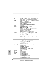
... 7.1 (Realtek ALC892 THX TruStudio ProTM - 2 x PCIE x1 Gigabit LAN 10/100/1000 Mb/s - Realtek RTL8111E Wake-On-LAN Energy Efficient Ethernet 802.3az LAN I /O 264 - ATX 規格 : 12.0 英吋 X 9.6 英吋 , 30.5 厘米 X 24.4 100 Intel® CoreTM i7 / i5 / i3 處理器... 個 PS/2 1 個 PS/2 1 個同軸 SPDIF 1 個光纖 SPDIF 4 USB 2.0 接口 - 1 個 eSATA3 接口 - 4 USB 3.0 接口 ASRock P67 Extreme6 Motherboard 簡體中文
... 7.1 (Realtek ALC892 THX TruStudio ProTM - 2 x PCIE x1 Gigabit LAN 10/100/1000 Mb/s - Realtek RTL8111E Wake-On-LAN Energy Efficient Ethernet 802.3az LAN I /O 264 - ATX 規格 : 12.0 英吋 X 9.6 英吋 , 30.5 厘米 X 24.4 100 Intel® CoreTM i7 / i5 / i3 處理器... 個 PS/2 1 個 PS/2 1 個同軸 SPDIF 1 個光纖 SPDIF 4 USB 2.0 接口 - 1 個 eSATA3 接口 - 4 USB 3.0 接口 ASRock P67 Extreme6 Motherboard 簡體中文
Quick Installation Guide
Page 289
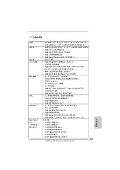
Realtek RTL8111E Wake-On-LAN Energy Efficient Ethernet 802.3az Teaming Dual LAN) I /O - ATX 規格 : 12.0 英吋 X 9.6 英吋 , 30.5 公&#...34899; - 7.1 Realtek ALC892 THX TruStudio ProTM - 2 x PCIE x1 Gigabit LAN 10/100/1000 Mb/s - Intel® P67 DDR3 2) - 4 個 DDR3 DIMM DDR3 2133( 超頻 )/1866( 超頻 )/1600/1333/1066 ...20809;纖 SPDIF 4 USB 2.0 接口 - 1 個 eSATA3 接口 - 4 USB 3.0 接口 289 ASRock P67 Extreme6 Motherboard 繁體中文
Realtek RTL8111E Wake-On-LAN Energy Efficient Ethernet 802.3az Teaming Dual LAN) I /O - ATX 規格 : 12.0 英吋 X 9.6 英吋 , 30.5 公&#...34899; - 7.1 Realtek ALC892 THX TruStudio ProTM - 2 x PCIE x1 Gigabit LAN 10/100/1000 Mb/s - Intel® P67 DDR3 2) - 4 個 DDR3 DIMM DDR3 2133( 超頻 )/1866( 超頻 )/1600/1333/1066 ...20809;纖 SPDIF 4 USB 2.0 接口 - 1 個 eSATA3 接口 - 4 USB 3.0 接口 289 ASRock P67 Extreme6 Motherboard 繁體中文

Quick Installation Guide
Page 290
... 0, RAID 1, RAID 10, RAID 5 和 Intel Rapid Storage), NCQ, AHCI 6 x SATA3 6.0Gb/s 接頭 - 1 x 1 x 1 x 1 x HDMI_SPDIF 接頭 - 1 x IEEE 1394 接頭 - 1 x CPU 24 針 ATX 8 針 12V SLI/XFire 4 x USB 2.0 8 USB 2.0 接口 ) - 1 x USB 3.0 2 USB 3.0 接口 ) - 1 x Dr. Debug (7 LED) - 1 個 LED CMOS 1 個 LED 1 個 LED 64Mb AMI BIOS - ACPI 1.1 ASRock P67 Extreme6 Motherboard
... 0, RAID 1, RAID 10, RAID 5 和 Intel Rapid Storage), NCQ, AHCI 6 x SATA3 6.0Gb/s 接頭 - 1 x 1 x 1 x 1 x HDMI_SPDIF 接頭 - 1 x IEEE 1394 接頭 - 1 x CPU 24 針 ATX 8 針 12V SLI/XFire 4 x USB 2.0 8 USB 2.0 接口 ) - 1 x USB 3.0 2 USB 3.0 接口 ) - 1 x Dr. Debug (7 LED) - 1 個 LED CMOS 1 個 LED 1 個 LED 64Mb AMI BIOS - ACPI 1.1 ASRock P67 Extreme6 Motherboard

