
Intel Rapid Storage Guide
Page 1
..., users can take advantage of the chipset and Serial ATA (SATA) hard drive. 1 AHCI also delivers longer battery life with an external drive. Valuable digital memories are protected against data loss in a RAID 0 configuration, data can be accomplished easily with Link Power Management (LPM), which can reduce the power consumption of...
..., users can take advantage of the chipset and Serial ATA (SATA) hard drive. 1 AHCI also delivers longer battery life with an external drive. Valuable digital memories are protected against data loss in a RAID 0 configuration, data can be accomplished easily with Link Power Management (LPM), which can reduce the power consumption of...

Intel Rapid Storage Guide
Page 12
... volume must be created, and the F6 installation method must be used to enter the BIOS Setup program after the Power-On-Self-Test (POST) memory test begins. 2. Click F2 or Delete to load the Intel® Rapid Storage Technology driver during POST, press Ctrl and i at the same time to...
... volume must be created, and the F6 installation method must be used to enter the BIOS Setup program after the Power-On-Self-Test (POST) memory test begins. 2. Click F2 or Delete to load the Intel® Rapid Storage Technology driver during POST, press Ctrl and i at the same time to...
User Manual
Page 3
... Layout 12 1.4 I/O Panel 13 2 Installation 15 2.1 Screw Holes 15 2.2 Pre-installation Precautions 15 2.3 CPU Installation 16 2.4 Installation of Heatsink and CPU fan 18 2.5 Installation of Memory Modules (DIMM 19 2.6 Expansion Slots (PCI and PCI Express Slots 21 2.7 SLITM and Quad SLITM Operation Guide 22 2.8 CrossFireXTM, 3-Way CrossFireXTM and Quad CrossFireXTM Operation...
... Layout 12 1.4 I/O Panel 13 2 Installation 15 2.1 Screw Holes 15 2.2 Pre-installation Precautions 15 2.3 CPU Installation 16 2.4 Installation of Heatsink and CPU fan 18 2.5 Installation of Memory Modules (DIMM 19 2.6 Expansion Slots (PCI and PCI Express Slots 21 2.7 SLITM and Quad SLITM Operation Guide 22 2.8 CrossFireXTM, 3-Way CrossFireXTM and Quad CrossFireXTM Operation...

User Manual
Page 6
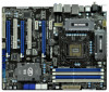
Advanced V8 + 2 Power Phase Design - Intel® P67 - capacity of system memory: 32GB (see CAUTION 1) - Supports Wake-On-LAN - Supports 2nd Generation Intel® CoreTM i7 / i5 / i3 in , 30.5 cm x 24.4 cm - Supports K-Series unlocked CPU -... Supports NVIDIA® Quad SLITM and SLITM - 7.1 CH HD Audio with Content Protection (Realtek ALC892 Audio Codec) - Supports LAN Cable Detection - Supports Intel® Extreme Memory Pro le (XMP) - 3 x PCI Express 2.0 x16 slots (PCIE2/PCIE4: single at x16 or dual at x8/x8 mode; Supports ATITM Quad CrossFireXTM, 3-Way CrossFireXTM and...
Advanced V8 + 2 Power Phase Design - Intel® P67 - capacity of system memory: 32GB (see CAUTION 1) - Supports Wake-On-LAN - Supports 2nd Generation Intel® CoreTM i7 / i5 / i3 in , 30.5 cm x 24.4 cm - Supports K-Series unlocked CPU -... Supports NVIDIA® Quad SLITM and SLITM - 7.1 CH HD Audio with Content Protection (Realtek ALC892 Audio Codec) - Supports LAN Cable Detection - Supports Intel® Extreme Memory Pro le (XMP) - 3 x PCI Express 2.0 x16 slots (PCIE2/PCIE4: single at x16 or dual at x8/x8 mode; Supports ATITM Quad CrossFireXTM, 3-Way CrossFireXTM and...
User Manual
Page 9
..., make sure to ne-tune different system functions in Flash ROM. ASRock website: http://www.asrock.com 7. This motherboard supports Dual Channel Memory Technology. Please check the table on page 13 for the operation procedures of your friends. ASRock Extreme Tuning Utility (AXTU) is an all-in-one tool to ...read the installation guide of memory modules on the processor. Only K-Series CPU can save the new BIOS le to update system...
..., make sure to ne-tune different system functions in Flash ROM. ASRock website: http://www.asrock.com 7. This motherboard supports Dual Channel Memory Technology. Please check the table on page 13 for the operation procedures of your friends. ASRock Extreme Tuning Utility (AXTU) is an all-in-one tool to ...read the installation guide of memory modules on the processor. Only K-Series CPU can save the new BIOS le to update system...

User Manual
Page 19
..., you have to install identical DDR3 DIMM pair in Dual Channel B (DDR3_A2 and DDR3_B2; It is not recommended to install a DDR or DDR2 memory module into DDR3 slot; Populated (3)* Populated Populated Populated Populated * For the con guration (3), please install identical DDR3 DIMMs in the slots of the ...same color. see p.12 No.7), so that Dual Channel Memory Technology can be damaged. 5. It is not allowed to install them in all four slots. Blue slots; In other words, install them either...
..., you have to install identical DDR3 DIMM pair in Dual Channel B (DDR3_A2 and DDR3_B2; It is not recommended to install a DDR or DDR2 memory module into DDR3 slot; Populated (3)* Populated Populated Populated Populated * For the con guration (3), please install identical DDR3 DIMMs in the slots of the ...same color. see p.12 No.7), so that Dual Channel Memory Technology can be damaged. 5. It is not allowed to install them in all four slots. Blue slots; In other words, install them either...

User Manual
Page 40
... (CPU module speci c) Pre-memory CPU initialization (CPU module speci c) Pre-memory North Bridge initialization is started Pre-memory South Bridge initialization (South Bridge module speci c) Pre-memory South Bridge initialization (South Bridge module speci c) Pre-memory South Bridge initialization (South Bridge module speci c) OEM pre-memory initialization codes Memory initialization. Programming memory timing information Memory initialization. 2.13 Dr...
... (CPU module speci c) Pre-memory CPU initialization (CPU module speci c) Pre-memory North Bridge initialization is started Pre-memory South Bridge initialization (South Bridge module speci c) Pre-memory South Bridge initialization (South Bridge module speci c) Pre-memory South Bridge initialization (South Bridge module speci c) OEM pre-memory initialization codes Memory initialization. Programming memory timing information Memory initialization. 2.13 Dr...

User Manual
Page 41
... section below) 0x31 Memory Installed 0x32 CPU post-memory initialization is started 0x33 CPU post-memory initialization. Application Processor(s) (AP) initialization 0x35 CPU post-memory initialization. Boot Strap Processor (BSP) selection 0x36 CPU post-memory initialization. Invalid memory type or incompatible memory speed 0x51 Memory initialization error. Invalid memory size or memory modules do not match 0x53 Memory initialization error. Cache...
... section below) 0x31 Memory Installed 0x32 CPU post-memory initialization is started 0x33 CPU post-memory initialization. Application Processor(s) (AP) initialization 0x35 CPU post-memory initialization. Boot Strap Processor (BSP) selection 0x36 CPU post-memory initialization. Invalid memory type or incompatible memory speed 0x51 Memory initialization error. Invalid memory size or memory modules do not match 0x53 Memory initialization error. Cache...

User Manual
Page 59
... item to keep the CPU from the chipset. This option will be hidden if the current CPU does not support No-Excute Memory Protection. 59 This option will be hidden if the installed CPU does not support Intel Virtualization Technology. Adjacent Cache Line Prefetch Use...Throttling You may select [Enabled] to enable CPU internal thermal control mechanism to turn on /off the MLC streamer prefetcher. No-Excute Memory Protection No-Execution (NX) Memory Protection Technology is [All]. The default value is an enhancement to [Enabled] if using Microsoft® Windows® XP, VistaTM,...
... item to keep the CPU from the chipset. This option will be hidden if the current CPU does not support No-Excute Memory Protection. 59 This option will be hidden if the installed CPU does not support Intel Virtualization Technology. Adjacent Cache Line Prefetch Use...Throttling You may select [Enabled] to enable CPU internal thermal control mechanism to turn on /off the MLC streamer prefetcher. No-Excute Memory Protection No-Execution (NX) Memory Protection Technology is [All]. The default value is an enhancement to [Enabled] if using Microsoft® Windows® XP, VistaTM,...

User Manual
Page 61
...]. Write Recovery Time (tWR) Use this item to change Row Precharge Time (tRP) Auto/Manual setting. The default is selected, the motherboard will detect the memory module(s) inserted and assigns appropriate frequency automatically. 3.3.3 DRAM Configuration Load XMP Setting Use this to change Command Rate (CR) Auto/Manual setting. Con guration options...
...]. Write Recovery Time (tWR) Use this item to change Row Precharge Time (tRP) Auto/Manual setting. The default is selected, the motherboard will detect the memory module(s) inserted and assigns appropriate frequency automatically. 3.3.3 DRAM Configuration Load XMP Setting Use this to change Command Rate (CR) Auto/Manual setting. Con guration options...

Quick Installation Guide
Page 6
.../2 Keyboard Port - 1 x Coaxial SPDIF Out Port - 1 x Optical SPDIF Out Port - 6 x Ready-to-Use USB 2.0 Ports - 1 x eSATA3 Connector ASRock P67 Extreme4 Motherboard English Supports DDR3 2133(OC)/1866(OC)/1600/1333/1066 non-ECC, un-buffered memory (see CAUTION 1) - Supports ATITM Quad CrossFireXTM, 3-Way CrossFireXTM and CrossFireXTM - Supports Wake-On-LAN - Supports LAN Cable Detection...
.../2 Keyboard Port - 1 x Coaxial SPDIF Out Port - 1 x Optical SPDIF Out Port - 6 x Ready-to-Use USB 2.0 Ports - 1 x eSATA3 Connector ASRock P67 Extreme4 Motherboard English Supports DDR3 2133(OC)/1866(OC)/1600/1333/1066 non-ECC, un-buffered memory (see CAUTION 1) - Supports ATITM Quad CrossFireXTM, 3-Way CrossFireXTM and CrossFireXTM - Supports Wake-On-LAN - Supports LAN Cable Detection...
Quick Installation Guide
Page 9
... Just launch this utility, you can press key during the POST or press key to BIOS setup menu to read the installation guide of memory modules on the processor. Please be less than 4GB for the reservation for optimal system performance. Only K-Series CPU can load the OC ...DDR3 frequency options may be noted that the USB flash drive or hard drive must use FAT32/16/12 file system. 9 ASRock P67 Extreme4 Motherboard English In Fan Control, it shows the major readings of output phases to improve efficiency when the CPU cores are allowed to update system...
... Just launch this utility, you can press key during the POST or press key to BIOS setup menu to read the installation guide of memory modules on the processor. Please be less than 4GB for the reservation for optimal system performance. Only K-Series CPU can load the OC ...DDR3 frequency options may be noted that the USB flash drive or hard drive must use FAT32/16/12 file system. 9 ASRock P67 Extreme4 Motherboard English In Fan Control, it shows the major readings of output phases to improve efficiency when the CPU cores are allowed to update system...

Quick Installation Guide
Page 15
...recommended to install identical DDR3 DIMM pair in the set of Memory Modules (DIMM) This motherboard provides four 240-pin DDR3 (Double Data Rate 3) DIMM slots, and supports Dual Channel Memory Technology. English 15 ASRock P67 Extreme4 Motherboard Blue slots; Populated - You may be activated. If ...you to install four DDR3 DIMMs for example, installing a pair of memory modules in DDR3_A1 and DDR3_A2, it is unable to the...
...recommended to install identical DDR3 DIMM pair in the set of Memory Modules (DIMM) This motherboard provides four 240-pin DDR3 (Double Data Rate 3) DIMM slots, and supports Dual Channel Memory Technology. English 15 ASRock P67 Extreme4 Motherboard Blue slots; Populated - You may be activated. If ...you to install four DDR3 DIMMs for example, installing a pair of memory modules in DDR3_A1 and DDR3_A2, it is unable to the...

Quick Installation Guide
Page 36
... reading the Dr. Debug codes. Configuring memory 0x2F Memory initialization (other) English 36 ASRock P67 Extreme4 Motherboard Serial Presence Detect (SPD) data reading 0x2C Memory initialization. 2.11 Dr. Debug Dr. Debug is started 0x1A Pre-memory South Bridge initialization (South Bridge module specific) 0x1B Pre-memory South Bridge initialization (South Bridge module specific) 0x1C...
... reading the Dr. Debug codes. Configuring memory 0x2F Memory initialization (other) English 36 ASRock P67 Extreme4 Motherboard Serial Presence Detect (SPD) data reading 0x2C Memory initialization. 2.11 Dr. Debug Dr. Debug is started 0x1A Pre-memory South Bridge initialization (South Bridge module specific) 0x1B Pre-memory South Bridge initialization (South Bridge module specific) 0x1C...

Quick Installation Guide
Page 37
... Post-Memory South Bridge initialization (South Bridge module specific) 0x3F-0x4E OEM post memory initialization codes 0x4F DXE IPL is started 0x33 CPU post-memory initialization. Invalid memory size or memory modules do not match 0x53 Memory initialization error. SPD reading has failed 0x52 Memory initialization error. 0x30 Reserved for future AMI error codes English 37 ASRock P67 Extreme4...
... Post-Memory South Bridge initialization (South Bridge module specific) 0x3F-0x4E OEM post memory initialization codes 0x4F DXE IPL is started 0x33 CPU post-memory initialization. Invalid memory size or memory modules do not match 0x53 Memory initialization error. SPD reading has failed 0x52 Memory initialization error. 0x30 Reserved for future AMI error codes English 37 ASRock P67 Extreme4...

Quick Installation Guide
Page 43
...friendly. It will enhance motherboard features. When you to select among the predetermined choices. It is designed to display the menus. 43 ASRock P67 Extreme4 Motherboard English The Support CD that will display the Main Menu automatically if "AUTORUN" is enabled in the Support CD. 4. If ... its test routines. For the detailed information about BIOS Setup, please refer to enter BIOS Setup utility; 3. BIOS Information The Flash Memory on the motherboard stores BIOS Setup Utility. To begin using the Support CD, insert the CD into your computer. Software Support CD...
...friendly. It will enhance motherboard features. When you to select among the predetermined choices. It is designed to display the menus. 43 ASRock P67 Extreme4 Motherboard English The Support CD that will display the Main Menu automatically if "AUTORUN" is enabled in the Support CD. 4. If ... its test routines. For the detailed information about BIOS Setup, please refer to enter BIOS Setup utility; 3. BIOS Information The Flash Memory on the motherboard stores BIOS Setup Utility. To begin using the Support CD, insert the CD into your computer. Software Support CD...

Quick Installation Guide
Page 232
... x 1 - 同軸 SPDIF x 1 - 光学 SPDIF x 1 ASRock P67 Extreme4 Motherboard Realtek RTL8111E - DDR3 2133(OC)/1866(OC)/1600/1333/1066 non-ECC, un-buffered 3 32GB ( 注意 4 Intel® Extreme Memory Profile (XMP 3 x PCI Express 2.0 x16 PCIE2/PCIE4: x16 で x8/x8...; Intel® CoreTM i7 / i5 / i3 in LGA1155 - 高度な V8 + 2 Intel® Turbo 2.0 K CPU 1 Intel® P67 DDR3 ( 注意 2 DDR3 DIMM x 4 - 日本語 1.2 仕様 CPU LAN I /O Panel - Premium Blu-ray THX ...
... x 1 - 同軸 SPDIF x 1 - 光学 SPDIF x 1 ASRock P67 Extreme4 Motherboard Realtek RTL8111E - DDR3 2133(OC)/1866(OC)/1600/1333/1066 non-ECC, un-buffered 3 32GB ( 注意 4 Intel® Extreme Memory Profile (XMP 3 x PCI Express 2.0 x16 PCIE2/PCIE4: x16 で x8/x8...; Intel® CoreTM i7 / i5 / i3 in LGA1155 - 高度な V8 + 2 Intel® Turbo 2.0 K CPU 1 Intel® P67 DDR3 ( 注意 2 DDR3 DIMM x 4 - 日本語 1.2 仕様 CPU LAN I /O Panel - Premium Blu-ray THX ...

Quick Installation Guide
Page 235
CD 59 Dual Channel Memory Technology 241 DDR3 K CPU の みが 2133 と 1866 への DDR3 Windows® 7 / VistaTM / XP 4GB 64 ビット CPU の Windows® OS 2 4 6 8 3 ASRock Extreme Tuning Utility (AXTU OC DNA、ES CPU OC DNA OC OC OC IES CPU ASRock Extreme Tuning Utility (AXTU Web ASRock Web サイト :http://www.asrock.com 日本語 235 ASRock P67 Extreme4 Motherboard BIOS 注意 1. 2. 3. 4. 5. 6.
CD 59 Dual Channel Memory Technology 241 DDR3 K CPU の みが 2133 と 1866 への DDR3 Windows® 7 / VistaTM / XP 4GB 64 ビット CPU の Windows® OS 2 4 6 8 3 ASRock Extreme Tuning Utility (AXTU OC DNA、ES CPU OC DNA OC OC OC IES CPU ASRock Extreme Tuning Utility (AXTU Web ASRock Web サイト :http://www.asrock.com 日本語 235 ASRock P67 Extreme4 Motherboard BIOS 注意 1. 2. 3. 4. 5. 6.

Quick Installation Guide
Page 257
...; - 1 個 eSATA3 接口 - 2 USB 3.0 接口 簡體中文 257 ASRock P67 Extreme4 Motherboard Intel® P67 DDR3 2 4 個 DDR3 DIMM DDR3 2133( 超頻 )/1866( 超頻 )/1600/1333/1066 non-ECC、un-buffered 3 32GB 4 Intel® Extreme Memory Profile(XMP) - 3 x PCI Express 2.0 x16 插槽 (PCIE2/PCIE4: 單插槽...
...; - 1 個 eSATA3 接口 - 2 USB 3.0 接口 簡體中文 257 ASRock P67 Extreme4 Motherboard Intel® P67 DDR3 2 4 個 DDR3 DIMM DDR3 2133( 超頻 )/1866( 超頻 )/1600/1333/1066 non-ECC、un-buffered 3 32GB 4 Intel® Extreme Memory Profile(XMP) - 3 x PCI Express 2.0 x16 插槽 (PCIE2/PCIE4: 單插槽...

Quick Installation Guide
Page 282
...個同軸 SPDIF 1 個光纖 SPDIF 6 USB 2.0 接口 - 1 個 eSATA3 接口 - 2 USB 3.0 接口 ASRock P67 Extreme4 Motherboard 繁體中文 ATX 規格 : 12.0 英吋 X 9.6 英吋 , 30.5 公分 X 24.4 100 Intel® ...; CrossFireXTM NVIDIA® Quad SLITM 和 SLITM 技術 - 7.1 Realtek ALC892 THX TruStudio ProTM - Intel® P67 DDR3 2) - 4 個 DDR3 DIMM DDR3 2133( 超頻 )/1866( 超頻 )/1600/1333/1066 non...
...個同軸 SPDIF 1 個光纖 SPDIF 6 USB 2.0 接口 - 1 個 eSATA3 接口 - 2 USB 3.0 接口 ASRock P67 Extreme4 Motherboard 繁體中文 ATX 規格 : 12.0 英吋 X 9.6 英吋 , 30.5 公分 X 24.4 100 Intel® ...; CrossFireXTM NVIDIA® Quad SLITM 和 SLITM 技術 - 7.1 Realtek ALC892 THX TruStudio ProTM - Intel® P67 DDR3 2) - 4 個 DDR3 DIMM DDR3 2133( 超頻 )/1866( 超頻 )/1600/1333/1066 non...

